1 Application
2 Consultation
3 Departure
4 Mounting
5 you are satisfied
Without such a responsible complex type works like installation of heating mains the arrangement of a single centralized or autonomous heating network is not bypassed. The function of this type of communications is to ensure the supply of heated coolant from a heat source end user and draining the cooled water back to the boiler room. The effectiveness of the functioning of the entire heating complex largely depends on how competently the pipeline project is drawn up, its laying, hydro- and thermal insulation, and sealing of joints are completed.
Copper pipes characterized by high throughput thanks to the completely smooth inner surface. This ability is maintained throughout their life due to their corrosion resistance. However, a layer of metal corrosion is additionally applied to the inner surface of copper pipes.
Due to the high ductility of copper, copper pipes are easily susceptible to machining which makes it easy to install necessary forms during assembly. Often pipes intended for heating installations, covered with outer polymer coated to improve their properties.
Depending on destination installation of heating mains can be produced for the needs utilities or individual owners, so they can be divided into:
- Industrial. Connect centralized boiler houses with complexes multi-storey buildings which they heat. Such external heating networks are distinguished by branching, power, scale of work on their arrangement.
- Household. Designed to supply heated coolant from a separate boiler house to the house and drain the cooled water on the way back. Usually they do not exceed several tens of meters in order to avoid excessive heat loss. Produce installation of heating mains this type is much easier, faster.
We guarantee:
- Departure of the measurer
- 60 months for all installation work
- Delivery of equipment without prepayment
- Free replacement of parts in case of breakage
Warranty for all types of work and materials
Polymer coating reduces heat loss during transport hot water, prevents condensation during transport cold water protects metal from scratches and other mechanical damage and also reduces the noise level. The coating also protects the tube from stray currents. The use of color coated copper pipes is recommended when pipes are to be installed in walls.
Installation requirements When using copper pipes to create heating systems, it is recommended to take into account the features and requirements for the heating system as a whole. Copper pipes are hardly compatible with other materials, so it is recommended to use homogeneous materials when building installations.
The cost of installation of heating mains
| Name of works | Explanations | Unit | Price* |
|---|---|---|---|
| Laying pipes for heating, water supply with a radiant (collector) heating system made of cross-linked polyethylene / metal-plastic up to D = 16-20 mm | m.p. | 55.00 rub. | |
| Laying pipes for heating, water supply at two-pipe system heating/heating risers made of cross-linked polyethylene/metal-plastic/polypropylene/copper up to D=32 mm | Laying of pipelines, fasteners, installation of fittings (tees, angles, adapters) | m.p. | 165.00 rub. |
| Laying of heating pipes made of cross-linked polyethylene/metal-plastic/polypropylene/copper D=40-63 mm | Laying of pipelines, fasteners, installation of fittings (tees, angles, adapters) | m.p. | 350.00 rub. |
| Steel pipe laying up to D=32 mm | Laying of pipelines, fasteners, installation of fittings, (tees, angles, adapters) | m.p. | 350.00 rub. |
| Threading on steel pipes | Threading on steel pipes up to D=32 mm | PCS | 300.00 rub. |
| Soldering copper connection | Soldering copper fittings(Price includes all expendable materials required for soldering) | PCS | 250.00 rub. |
| Installation of pipe thermal insulation for pipes with a diameter of D=16-32 | m.p. | 25.00 rub. | |
| Installation of pipe thermal insulation for pipes with a diameter of D=40-63 | Pipe insulation, sealing of pipe thermal insulation joints | m.p. | 40.00 rub. |
| Installation of a heating main of a ready-made factory design such as "Uponor", "Microflex" | Laying of heating main pipelines in a trench, anchoring of inputs to the building, purging and pressure testing of the route (without land and construction work) | m.p. | 400.00 rub. |
| Installation of a heating main in a sleeve from a sewer pipe up to D=40 mm | Laying and insulation of heating pipelines in sewer pipe in a trench, purging and pressure testing of the route (without land and construction work) | m.p. | RUB 850.00 |
Industrial heating networks
 Before producing installation of heating mains must be drafted with detailed description location, materials used, method of laying, calculation of the cost of materials, excavation, installation, commissioning. This document is approved by the relevant authorities.
Channelless construction of heating mains
On the other hand, when copper pipes are connected to heating systems, some restrictions on the connection methods used are eliminated due to the lack of oxygen in the water. standard method is capillary soldering with hard and soft solder. Welding is used, as well as fastening under pressure.
It's good to keep in mind that it's not recommended to use a flexible pipe fitting if it runs through a wall or is otherwise covered. The design of heating systems allows the use of steel and copper products, and the “water flow rule” may not be respected. The reason is that in a well-functioning system, gases evaporate from the water and there is no dilute oxygen in the system.
An important moment of competent installation of heating mains consists in the choice of building materials for the arrangement of the pipeline: pipes, insulation, trays, plates. So the most popular for the installation of heating mains are the following types pipes:
- pressure asbestos-cement;
- bimetallic;
- steel galvanized;
- enamel coated steel.
Since most of the heat loss comes from outdoor pipeline, when installing heating mains increased attention should be given to thermal insulation. most popular insulating materials on the modern market are:
However, it is good to keep in mind that copper and steel, copper and aluminum are in direct contact. Otherwise, it may lead to corrosion. It is advisable to provide a brass fitting or a nickel-plated brass fitting for copper-aluminum connections. If possible, the heating system should be closed to prevent oxygen from entering the system.
Calculate the cost of building heating networks for you
The advantages of copper pipes indicate their ability to fit into the floor. Copper pipes are considered very suitable solution for construction solar installations for the production of hot water. Among the advantages mentioned are good thermal conductivity, easy bonding, good corrosion resistance due to atmospheric influences and the effect of water. Under normal operating conditions copper pipeline is over 40 years old. During this long period, the pipes are practically independent of the pressure and temperature of the refrigerant in the grid.
- fiberglass;
- foamed rubber;
- polyurethane foam;
- basalt.
Methods for installing heating mains
Depending on the sequence, the specifics of the pipeline laying work, the following types of installation are distinguished:
- Channel.
- Channelless.
- Outer.
Channel pipe laying
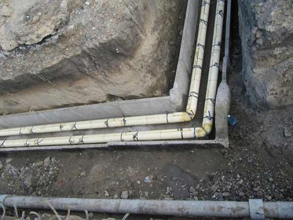
 It is produced in trays specially made of reinforced concrete or concrete. First, a trench is developed, its bottom, walls are carefully leveled, a heat cable is laid down, which further reduces heat loss.
In floor heating systems, in addition to pipes, the kit includes collectors and racks to which pipes are connected. Floor heating, underfloor heating and underfloor heating systems supplied by manufacturers of underfloor heating systems allow you to combine heating systems and thus maintain the required climatic conditions in the premises.
As part of energy efficiency programs, it is interesting to use room thermostatic temperature controllers installed in the heating circuit. With their help, the required temperature in the room is automatically maintained by the residents. This device is a small compact block which can be installed in a suitable convenient location, for example, at the entrance to the room.
Channelless laying method
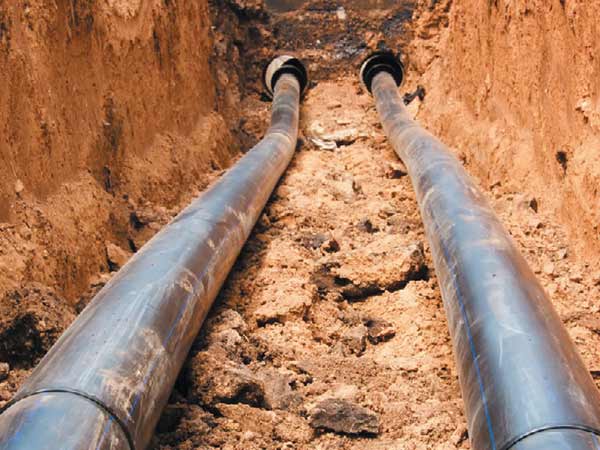
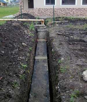
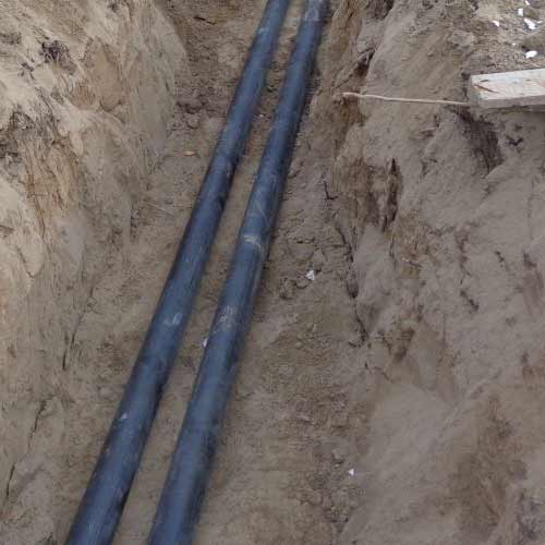 The most common, as it requires least cost time, materials. In this case, the pipes are laid on the bottom of the trench without installing additional structures. Begins installation of a heating main with trench preparation. Its bottom, walls are leveled, covered with sand. Thickness sand cushion must be at least 10 cm.
Photos of completed works
AT modern systems floor heating, polypropylene, polybutylene and cross-linked polypropylene pipes. Currently, most systems use a pipe with protective layer which prevents oxygen from entering the refrigerant.
Polymer tubes are highly resistant to stress, thermal aging, plasticity and flexibility. Such pipes are corrosion-resistant, impact-resistant and no sediment is deposited on their inner surface. Pipe installation must not exceed the allowable radius of curvature, and only components specified by the manufacturer must be used for the coupling. This is good method cold pressing. This compounding method is absolutely hermetic and reliable, which allows you to place the system under a monolithic floor.
After thermal insulation, the laying of the heat pipe is back-filled with sand. Concrete slabs are laid on top, waterproofing, soil is poured. This method of installation of heating mains is unacceptable when there is a risk of groundwater flooding at the installation site or the construction of any structures is planned.
Outside piping
 It is used quite rarely due to the complexity of the work, the need for particularly thorough thermal and waterproofing. It is used for the installation of temporary structures or when necessary, when communications already lie in the ground or groundwater flows.
It also simplifies and speeds up the design and installation process, there is no waste; work with large quantity pipes big size. In general, the installation of underfloor heating is carried out as follows. Thermal insulation applied to flat base. In addition, the pipe is positioned at a certain pace and in the required configuration. In the case of large heated rooms, combined pipe installation is also used. Making decisions for the configuration of the pipe installation are made by the room designer and its designer in order to rational use thermal power of the installation.
Outer installation of heating mains consists in the installation of strong high supports, on which sliding supports are mounted. Fit securely on top insulated pipes. The most commonly used insulation mineral wool mats, wrapped waterproofing film or metal casing.
Installation of domestic heating mains
 Often the boiler room is autonomous heating system located outside the house in a separate standing building. This provides additional security, since all potentially fire hazardous equipment is located remotely from housing. This is convenient if you need to provide heat to several buildings.
Also considered are the size, location and purpose of the room, the configuration of the exterior walls and the position of the windows, the location of the prefabricated unit or pillars, and the need for expansion joints and their location. Laying pipes in accordance with the accepted scheme heating circuit and their connection to the heat-insulating boards is carried out either with the help of brackets or window sills different configuration located in a network of individual panels, or using elongated rods and other methods.
Mounting panels maximize the assembly process. They are most often used when installing heating circuits on roof slabs. For a stronger connection, they are equipped with grooves. Heat treatment The surface of the blocks protects the pipes from damage before they are fixed.
Domestic installation of heating mains significantly differs from the industrial one in terms of scale, materials, and the specifics of the work performed. So it is recommended that the distance from the boiler room to the heated building does not exceed 50 m, so that heat losses in the pipeline do not exceed the norm.
Steel, asbestos-cement pipes are too heavy, overall for autonomous complex, so they have long been replaced by polyethylene products. They are sold already hydro- and thermally insulated, completely ready for laying, which greatly facilitates installation of heating mains into the ground.
For underfloor heating in rooms with low ceilings or in refurbished rooms, more compact mini-blocks with fixtures are used. If the system is to be installed on large areas, the fixing system is used with brackets on insulating pads covered with a waterproof film and the required stepped pipes. There is also a corresponding easing tool.
The pipe can be installed on the metal mesh at a certain pace. The canvas is installed directly on the protective film, and the pipes are attached to it. The network after laying the cement screed over the floor strengthens it and further increases its mechanical strength.
The most widespread pressure pipes from molecularly cross-linked polyethylene. Thanks to the unique production technology, they have highest performance strength, durability, resistance to water hammer, high temperatures. Polyethylene does not corrode, has low thermal conductivity, retains its original properties when in contact with an aggressive coolant, its smooth surface prevents dirt particles from depositing on the walls, so the heat pipe does not overgrow.
After the pipes are installed and the pipeline is turned on, the system is tested, after which the cement slurry is poured. It should be borne in mind that when designing floor heating for rooms with a larger surface, a map of individual sections of the system is created - modules, the sections of which are poured separately. There is a distance between the modules - a temperature seam that perceives and assumes thermal expansion cement mortar. Due to the fact that the pipe can pass through several modes of the system, at the passages through the expansion joints, part of the other corrugated pipe relies on the main pipe or a special metal sleeve is placed.
 The presence of "molecular memory" facilitates installation of heating mains made of cross-linked polyethylene, since after flaring the pipe quickly takes its initial shape, clasping the fitting. At the same time, it is flexible, it allows you to lay a heat pipe of any design, bypassing decorative elements, site buildings.
The implementation of the system requires attention to the following points. All Finishing work in rooms must be filled before installing pipes to avoid damage or contamination. Before installation, it is necessary to make water and vapor barrier of the floor and walls.
After the cement screed, it is necessary to wait the necessary time to fully and properly cover cement screed on the floor until the underfloor heating system is switched on. On the prepared "warm floor" you can apply almost any floor coverings, which must be selected in advance, at the stage of system design, during initial calculations.
Complete with a pipe there is a thermal insulation from the made foam cross-linked polyethylene which is characterized by the minimum absorption of moisture, excellent flexibility. The pipe with thermal insulation is placed in a two-layer protective casing made of high-density polyethylene, produced according to the technology low pressure(PND). The combination of these materials makes it possible to produce high-quality mounting heating mains for many years.
Manufacture of steam and heating installations. Speaking of underfloor heating, we must definitely note the fact that this is one of the optimal solutions for comfort. It is also very economical because it creates an almost perfect temperature profile between floor and ceiling.
You are probably asking yourself, "Why is this heating method so effective?" The answer is simple: heating the water in half achieves the same results as the traditional centralized heating, but works for much more low temperatures and increases heat storage.
Are being laid polyethylene pipelines channelless method, i.e. placed in a pre-dug trench. Through the use quality materials, not afraid of frost, you can make a shallow ditch (0.5-1.5 m). The trench is covered with a layer of sand, on which installation of a heating main. It is also desirable to pour sand on top, the texture of which allows you to create a denser backfill, which gives less shrinkage.
Water heating systems are becoming more and more popular. This is because they maintain a constant temperature throughout the room, are easy to maintain, are quiet in operation, and are extremely economical in terms of electricity and heat bills. Basically, the most efficient system heating must contain all known forms of heat transfer - radiation, convection and conduction.
At different people another feeling of heat and cold. Therefore, when designing underfloor heating, it is necessary to provide for the satisfaction of needs as much as possible. more people living or working in the building. For achievement following conditions you need to find the best combination.
It is better to strengthen pipeline transitions through the walls of buildings so that the weight wall structure did not damage the pipe. To do this, it is placed in a metal box, the gap between it and the heat pipe is filled with foam. At the final stage of installation of the heating main, it is pressure tested.
Run this species works, even on a domestic scale, are only possible for experienced qualified specialists who have at their disposal special tools. Everything you need to produce quality installation of heating mains available from Alfa-Therm. Our designers will make a competent project with accurate calculation location, method of laying the heat pipe, managers will help with the selection necessary building materials, the installers will qualitatively perform the entire range of works from digging a trench to the final arrangement of the territory within the agreed time frame.
Thermal comfort AestheticsEconomyMinimum maintenanceEcology and hygiene. . Practice has proven that in an ideal working environment or sport, there is no need for a large temperature difference between the floor and the ceiling of a heated room. Most characteristic feature underfloor heating is that it is low temperature and provides an even distribution of heat throughout the room, just above the floor - i.e. where people move or work.
The principle of operation of water heating. There are three types of floor and wall heating: water, electric and air. Here we will focus on water heating systems. They are made of metal or plastic pipes embedded in a floor or wall where hot water flows, giving it warmth environment. Already cooled water returns to the heating source, where it is heated again and enters the system. This process is known as a "closed loop system". Pipes are built into concrete slab or installed on metal mesh and cement is applied on top.
Installation of heat networks, which must be carried out by the in-line method, includes earthwork, assembly and welding, stone, concrete, reinforced concrete, insulating, pressure testing, carpentry and other works.
With a properly organized flow method of construction, work is carried out in a certain technological sequence. The flow is organized in such a way as to most economically manage forces and means, to perform a large amount of work in a short time, at low cost and with high quality construction.
Heating networks in cities and other settlements are laid in specially designated for construction engineering structures lanes, parallel to the red lines of streets, roads and driveways outside the carriageway and green spaces. When justified, it is possible to lay networks under the carriageway and sidewalks.
For heating networks, underground laying is mainly provided, less often - aboveground(in the territories of enterprises, outside the city, with a high level ground water, in areas permafrost and other cases where underground laying is impossible or impractical).
When laying underground, pipelines of heating networks (heat pipelines) are laid in channels - special building structures, protecting pipelines, or channelless. Channels can be through and non-through. Depending on the adopted design underground laying(in impassable or through channels, collectors) it is allowed to lay heating networks together with other engineering networks(water supply, communication cables, power cables, pressure sewerage).
With above-ground (open) laying, heat pipes are laid on brackets along the walls of buildings, on concrete, reinforced concrete and metal supports. When passing heat pipes through railways and water barriers use bridge structures. Heat pipelines laid under the bed of a river or canal, along the slopes and bottom of the ravine, are bent in accordance with the terrain. Such structures are called siphons. When laying under the riverbed, heat pipelines are enclosed in steel pipes (cases). Against the ascent, the pipes are held by weights. This is how other types are built. underground networks(water supply, gas pipeline and sewerage) when they cross rivers, ravines and other similar obstacles.
Assembly steel pipes large diameters into links using a pipe-laying crane. Prior to the start of pipe assembly, pipes are brought into the links and laid out along a pre-marked axis; clean the ends of the pipes from contamination and straighten the deformed edges.
Steel pipes are assembled into links in the following sequence: the beds are laid and aligned, the pipes are laid on the beds using a pipe-laying crane; clean and prepare pipe edges for welding; center the joints with a centralizer, supporting the pipes with a pipe-laying crane during the tacking of the joint by electric welding; pipe joints are welded with the pipe link turning; the beds are removed and the assembled link is installed on the inventory linings.
Laying and alignment of beds. Pipelayers, pulling the tape measure along the axis of the layout of the links, mark on it the places for laying the beds. Then they bring the beds and lay them out according to the markings, while the middle of the beds should coincide with the axis of the layout. At the ends of the extreme beds, four metal pins are hammered and a twine is pulled between the extreme beds at the level of the top of the beds. Focusing on this level, intermediate beds are installed, cutting off or knocking out the soil under them with shovels.
Laying pipes on the bed. Having marked the middle of the pipe with a tape measure, the pipe-laying crane is installed so that its boom is above the center of gravity of the pipe. The pipe is slinged, and the crane operator lifts it by 20-30 cm. After making sure that the slinging is reliable and correct, the crane operator lifts the pipe to a height of 1 m and, at the command of the pipelayer, lays the pipe on the bed. Pipelayers, standing at both ends of the pipe, keep it from turning.
Cleaning and preparation of pipe edges for welding. When loading, transporting or unloading, ellipticity, dents, etc. may form at the ends of the pipes. If necessary, the ends of the pipes should be straightened. The curvature of the ends is straightened with the help of screw jacks or manually by hitting a sledgehammer with preheating pipes at the point of straightening.
In the event that the deformed ends cannot be straightened, they are cut off by gas cutting, followed by cleaning the edges.
Using chisels and hammers, pipelayers clean the edges of pipes from dirt and ice. Electric grinders, files, reversible angular pneumatic brushes clean the edges up to metallic luster for a length of at least 10 mm from the outside l from the inside.
Centering the joint and supporting pipes when tacking the joint. The driver sets the pipe-laying crane opposite the middle of the pipe and lowers the towel sling. The pipelayer slings the pipe and gives the command to lift it by 0.5 m and move it to the docking point. After moving the pipe, the workers lay it on the beds, visually center the joint, straighten and fix the pipe on the beds with wooden stakes. Then a centralizer is installed on the joint and the joint is fixed by turning the handle.
The electric welder, having checked the gap between the ends of the pipes to be joined along the entire circumference with a universal template and making sure that the size of the gap corresponds to the norm, welds the joint.
If, when checking with a template, the gap between the ends of the pipes does not meet the regulatory requirements, the pipelayers loosen the centralizer, the crane operator changes the gap with the movement of the boom, while the pipelayers help him with crowbars. After obtaining the required gap, the position of the pipe is finally fixed with wooden wedges, the centralizer lever is tightened to failure, and then the joint is seized by welding. After tacking the joint, the pipelayers remove the centralizer.
Turning the link when welding pipes. After applying a seam to a quarter of the circumference of the pipe on each side, the pipelayers turn the link, fixing it with wooden wedges on the beds at the joint.
Installation and welding of mobile supports. Movable supports perceive the load from the weight of the heat pipe, in addition, ensure the movement of the pipeline in the axial direction, which occurs due to a change in its length with a change in temperature. Factory-made movable supports are sliding, skid, roller, suspended. Of the listed designs of movable bearings, sliding bearings are the most widely used.
Sliding supports can be low and high, normal length and shortened. The type of support is chosen depending on the thickness of the thermal insulation and the distance between the supports. Low (linings) and high supports protect pipes from abrasion when moving heat pipes. In addition, high supports protect the thermal insulation from contact with the base of the channel.
Sliding supports are installed on the support stones with some displacement towards the fixed support. When starting hot water, the pipeline will heat up and lengthen somewhat; the sliding support welded to the pipeline will shift towards the compensator and take up a working position on the support stone. If the sliding support is installed on the support stone without mounting offset, then it can come off the support stone during the operation of the heat pipeline. The sliding support moves along a metal lining, concreted into the support stone and protruding above its upper plane.
The distance between the sliding supports depends on the distance between the supporting stones, which in turn is taken depending on the nominal diameter of the pipes.
It is not allowed to weld sliding supports in places of welded joints. The support must be welded without lateral displacements in relation to the vertical axis of the pipeline.
Having marked the installation sites of the supports on the pipes, they are adjusted in place, grabbed and welded. Sliding supports are welded before pressure testing of the pipeline, as on a pipeline that has passed hydraulic or pneumatic test pa density and strength, it is not allowed to carry out welding work.
Installation of stuffing box compensators. Gland compensators perceive axial temperature deformations of pipelines of heating networks and thereby protect the pipeline and fittings from destructive stresses.
Gland compensators are made one-sided and two-sided. The compensating capacity of a double-sided compensator is twice that of a single-sided compensator.
The compensator is connected to the main pipeline by welding.
The compensator is installed in the extended position to the full length of the stroke, which depends on the compensating capacity, with a gap between the body thrust ring and the safety ring on the sleeve. The gap compensates for the change in the length of the pipeline when the temperature of the pipes drops after the compensator is installed (due to a decrease in the outside air temperature).
When installing the compensator, the stuffing box seals (gland) should be carefully stuffed, since the replacement of the stuffing during operation leads to a shutdown of the heating networks. The joints of the stuffing box rings must be displaced relative to each other, the seams of the stuffing box compensators must be even, and the craters must be welded.
Flange installation. Pipe fittings and linear equipment are connected to the pipeline by welding or by flanges tightened with bolts, studs and nuts. Conditional internal pressure in the pipeline up to 40 kgf / cm2 (4 MPa) bolts are used, at 40 kgf / cm2 or more studs. The density of the flange connection depends on the accuracy of the surface treatment of the flanges, the quality of the bolts and the uniformity of their tightening. The flanges must be parallel to one another.
Flanges are welded perpendicular to the axes of the nozzles. The misalignment should not exceed 1 mm per 100 mm of the outer diameter of the flange (but not more than 3 mm). After fitting the flanges, two or three bolts are installed in place to align the gasket, then the remaining bolts are mounted, nuts are screwed onto them and the flange connection is tightened. To avoid distortion, the nuts are tightened gradually in a crosswise manner.
The diameter of the bolts must match the diameter of the holes of the flanges to be connected.. The bolt heads are located on one side of the joint. Flanged bolts may protrude above the nut by at least three threads and by no more than half the bolt diameter. It is necessary that the inner diameter of the gasket matches the inner diameter of the pipe with a tolerance of 3 mm, and its outside diameter must be not less than the diameter of the connecting ledge and not more than the diameter of the circle tangent to the bolts.
For a tighter fixing of the gasket, sometimes a protrusion is made on one of the flanges to be connected, and a depression on the other. The protrusion enters the cavity, and thus the gasket is securely fastened between the flanges. For the same purpose, concentrically located recesses - risks are applied to the mirror of the flanges.
When installing pipe fittings , for example gate valves, excessive tightening of the flanges with bolts should not be allowed, since the density and strength of the flange connection is reduced.
Stretching U-shaped compensators. To increase the compensating ability, U-shaped expansion joints are stretched. The stretching value specified in the project should be equal to half the elongation of the compensated section. The compensator is stretched only after fixed supports are installed on its two sides; thus, when the expansion joint is stretched, the pipeline remains motionless at the points of its welding to the supports. Only one joint remains unwelded - in the place of expansion joint stretching.
The compensator is stretched with the help of corner ties, jacks, hoists, etc.. At an equal distance along the circumference of the pipe of the U-shaped compensator, four plates are welded, and four plates are welded to the previously laid pipe. The distance between the plates must not exceed the length of the tie bolts. Coupling bolts are inserted into the hole of the plates and, by screwing the nuts, the compensator is stretched, bringing the edges of the pipes together to the gap required for welding. The joints are seized by electric welding, the plates are cut off with a gas cutter and the joint is welded.
Installation of heating network nodes. The pipelayer cleans the ends of pipes and pipes from rust and dirt with a steel brush or file. Then, using a crane, the unit is fed into the heating network chamber, where it is installed in the design position. After that, the edges are adjusted and trimmed and the joints are centered with an external centralizer. The joints are welded, the centralizer is transferred to the next work.
You may also be interested in:


")


