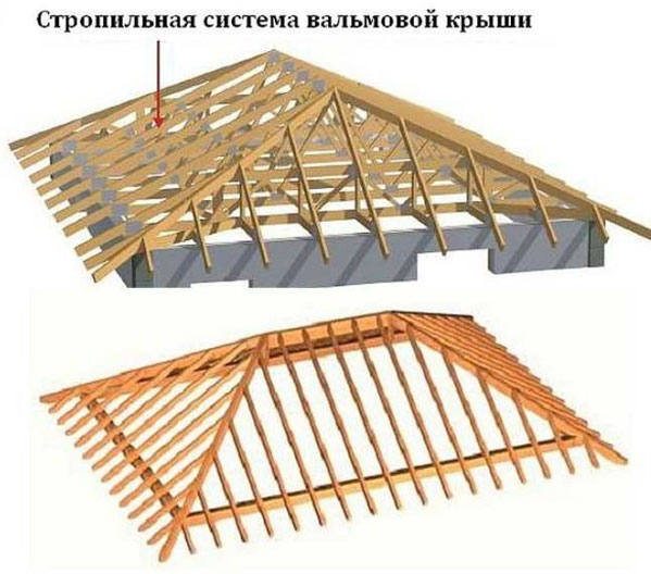
In private housing construction, in addition to common gable roofs more durable and rigid four-slope structures are often used. They are distinguished by the absence of pediments, which replace the triangular slopes that cut off the ends of the ridge ridge. This configuration makes four-pitched roofs very attractive and economical, despite the fact that during their construction the length of the eaves overhangs increases, the number downpipes and gutters. Therefore, they deserve the closest attention.
Varieties of truss systems for hipped roofs
The device of the truss system depends on the shape of the hipped roof. The following configurations are the most common today.
- Hip structure. All four slopes occupy the area from the ridge to the cornice overhang, while two side slopes are trapezoid in shape, and two end slopes (hips) are triangular. A feature of the truss hip frame is the presence of two pairs of diagonally installed layered rafters that extend from the edge of the ridge and serve as supports for sprenels and sprengels.
The hip four-slope design is characterized by the fact that the slopes occupy the entire area of the roof - from the ridge to the cornices
- Dutch half hip. A device with truncated end slopes that do not reach the eaves. As a rule, they are 2-3 times smaller than trapezoidal ones. The advantage of this four-slope roof structure is the possibility of installation at the ends of the house normal window, as well as the absence of a sharp protrusion typical of gable roofs, which greatly increases the wind resistance of the structure.
The Dutch half-hipped roof has truncated triangular slopes and part of the gable into which a conventional vertical window can be installed.
- Danish half hip. It is characterized by the presence in the triangular slopes of the pediment at the ridge, which allows for full natural lighting of the under-roof space without installing skylights.
- Tent construction. It is installed on houses with a square frame. All four slopes of a hipped roof are the same isosceles triangles connected at one point. During the construction of such a roof important aspect is to maintain symmetry.
The structure of the four-slope truss system depends on the chosen roof configuration
Features of the supporting frame of the hipped roof
We note right away that the truss system of a four-pitched roof will be more complex than traditional gable roof structures for two reasons.
- Due to the increase in the number of inclined planes and their docking with each other. At its core, the connection of the slopes is the intersection lines running at a certain angle to the horizon. The joints that form an angle protruding above the surface of the slopes are called roof ribs. From them, water flows down the slopes and accumulates in the grooves (valleys) - the lines of intersection with the inner corner. If all planes have the same slope, then the ribs and valleys divide the base angle at the junction of adjacent slopes in two and create a slope of 45 ° to the perimeter of the building.
Four-pitched truss systems are distinguished by the absence of full gables, instead of which there are two triangular end slopes, as well as the presence of two lateral trapezoidal inclined planes, grooves and ribs
- Due to the fact that the runs in the four-slope structure form a closed loop, where the hip (diagonal) rafter legs are located along the lines of the ribs and valleys. They are longer than ordinary beams, which are installed longitudinally to the slopes at a distance between intersections. hip rafters in the top harness. But between the lower parts of the diagonal legs, short rafters, called sprigs, are mounted. A distinctive feature of the four-pitched roof frame is the presence of sprengels - wooden struts under the hip rafters.
Support runs in four-pitched structures have a closed contour, where diagonal rafter legs are located along the lines of valleys and ribs
Main structural elements truss system of a hipped roof are:

Thus, the number of elements of the truss system of a four-pitched roof is much greater than, for example, gable design, and this, of course, increases the cost of its construction. However, in general, as we noted above, the arrangement of a hipped roof will cost a little more due to savings on laying roofing cake because the waste insulating materials and covering flooring when cutting into a multi-pitched structure will be much less.
Despite the fact that the truss system of the four-slope structure is more complex and expensive, the construction of the entire roof is more profitable due to savings on the arrangement of the roofing pie.
In addition, the four-slope design:

Video: gable or four-pitched roof - what to choose
How to calculate the truss system of a four-pitched roof
The supporting structure of a four-pitched roof can be layered if the building has solid internal walls, or hanging when intermediate supports are not included in the building. With a hanging device, the rafters rest on the walls of the house and exert a bursting force on them. To relieve the load on the walls in such cases at the base rafter legs mount a puff connecting the rafters to each other.
The use of a layered structure makes the frame lighter and more economical due to the fact that less lumber is required for its arrangement. Because of this, a layered truss system is used in the construction pitched roofs much more often. But regardless of the type of rafters used, only the correct calculation of the supporting frame and precise marking raise economic effect from the construction of a four-slope structure.
Marking and calculation of the supporting frame of a hipped roof
When calculating the truss system, you must adhere to the following rules.

To determine the installation location of the rafters and find their length, you will need a template.
Using a template will make measurements and calculations much easier. roof frame hipped roof
The length of the rafter leg can be determined by its laying (horizontal projection). For this, there is a special table of coefficients, presented below. The length of the rafter is determined by the size of its projection, multiplied by a coefficient corresponding to the slope of the slope.
Table: the ratio between the length and laying of the rafters
| Roof slope | Coefficient for calculating the length of intermediate rafters | Coefficient for calculating the length of the corner rafters |
| 3:12 | 1,031 | 1,016 |
| 4:12 | 1,054 | 1,027 |
| 5:12 | 1,083 | 1,043 |
| 6:12 | 1,118 | 1,061 |
| 7:12 | 1,158 | 1,082 |
| 8:12 | 1,202 | 1,106 |
| 9:12 | 1,25 | 1,131 |
| 10:12 | 1,302 | 1,161 |
| 11:12 | 1,357 | 1,192 |
| 12:12 | 1,414 | 1,225 |
| Note: when erecting a roof frame for which there are no data in the table (for non-standard slopes of slopes), the parameters should be calculated using the Pythagorean theorem or a mathematical proportion should be used. | ||
Consider an example: building private house in Yekaterinburg with a size of 7.5x12 m with a planned height hip roof from metal tiles 2.7 m.
- First of all, we draw a drawing or a sketch of the roof.
Before calculating the truss system, it is necessary to make a sketch of the building and apply all the initial data to it
- We find the angle of inclination of the slopes using the formula: the tangent of the angle of inclination is equal to the ratio of the height of the roof to half the length of the span, in our case, to half of the end side L = 7.5 / 2 = 3.75. Thus, tg α = 2.7 / 3.75 = 0.72. According to the reference tables, we determine: α = 36 °, which corresponds to the standards providing for a roof slope for metal tiles of at least 14 °, and the climatic conditions of Yekaterinburg.
The tangent of the angle of inclination of the slopes is determined by the well-known formula for calculating the sides right triangle as the ratio of the opposite leg to the adjacent
- We determine the position and edge of the ridge ridge, for which we apply the template at an angle of 36 ° in the middle top harness end (place of installation of the first central intermediate rafter) to a height of 2.7 m and design the outline on the sketch.
- We retreat ½ of the thickness of the ridge beam from the axial (key) line and set the end of the measuring rail at this point. At the other end of the rail, we make marks for the outer and inner contours of the side wall, as well as the overhang. We turn the rail to the side and from inner corner external strapping, we mark the laying of the intermediate rafter at the mark of the inner contour, thus determining the installation location of the second intermediate central rafter.
When arranging the truss frame of a four-pitched roof, the position of the central rafter legs is initially determined using a template and a measuring rail
- We carry out similar actions at all corners, determining the edges of the ridge ridge and the location of all central rafter legs.
- After planning the intermediate rafters, we determine their length from the table. In our example, the slope angle is 36°, its tangent is 0.72, which corresponds to a ratio of 8.64:12. There is no such value in the table, so we calculate the coefficient relative to the line with the parameter 8:12 - 8.64/ 8 = 1.08. Hence, the desired coefficient is 1.202 1.08 = 1.298.
- Multiplying the depth of the intermediate rafters by the calculated coefficient, we find their length. Let's take into account the laying depth of 3 m, then L str \u003d 3 1.298 \u003d 3.89 m.
The length of ordinary and central intermediate rafters depends on the angle of inclination of the roof and the depth of their laying
- Similarly, we determine the length of the diagonal rafters, having previously calculated the laying equal to the distance from the angle of connection of the side and end slopes to the first intermediate central rafter. According to the initial data, the laying of the corner rafters is 7.5 / 2 = 3.75 m. Then the estimated length of the corner rafters will be 3.75 1.298 = 4.87 m.
Corner rafters differ from intermediate device undercuts with double bevel in the ridge area, deeper and longer undercuts for the bearing part
- We calculate the overhang according to the Pythagorean theorem according to the markings made, or simply add the desired size to the length of the rafters, for example, 0.6 m plus at least 0.3 m for arranging an external drain.
To calculate the length of the overhang, you need to multiply its placement by the coefficient for an intermediate or corner rafter or to effective length rafters add the planned length of the overhang and at least 0.3 m for organizing an external drainage system
- Having marked all the elements of the truss frame, we determine the length of the ridge ridge, which is equal to the difference in the length of the side and twice the value of laying the intermediate rafters: 12 - 2 3 = 6 m. It is at this distance that ordinary rafters will be installed. If you take a step of 1 m, then you need 5 ordinary rafters, equal in length to the central ones. In addition, at the site of laying the intermediate central rafters, having a length of 3 m, two short rafters will be installed from one and the other edge of the side.
- Since the short rafters (spreaders) are attached to the diagonal ones, it means that two rafters will also be installed on the end sides between the corner and central intermediate rafters on the left and right.
Let's summarize the preliminary result - for the truss frame of a four-pitched roof you will need:
- two pairs of hip (corner) rafters with a length of 4.87 + 0.6 + 0.3 = 5.77 m;
- three pairs of intermediate central rafters 3.89 + 0.6 + 0.3 = 4.79 m long;
- five pairs of ordinary rafters 4.79 m long.
Only ten pairs of rafters, the total length of which will be approximately 100 running meters. We add here 6 m for the ridge beam, as well as a ten percent margin, and we get that approximately 117 linear meters of lumber are needed to make a simple hip truss frame with struts, struts, crossbars, trusses and fillies. But if racks and a bed are provided in the design, then they will have to be calculated separately or a larger percentage of the stock should be added.
Video: four-pitched roof truss system, installation technology
https://youtube.com/watch?v=n_Yr2QB3diMThe measuring rail makes the work very easy and helps to avoid grossest mistakes during measurements. It is most often made independently from plywood 50 mm wide.
A few words need to be said about short rafters. They are calculated in the same way as the intermediate ones: the laying multiplied by the coefficient for the intermediate rafters from the table. However, the task can be facilitated and the length of the sprigs can not be calculated specifically, since the percentage of the stock is taken sufficient, and the trimming of the boards will be needed for the manufacture of structural reinforcing elements - struts, struts, crossbars, etc.
The length of short rafters (spiders) can not be calculated, since lumber trimmings are useful for the manufacture of reinforcing structural elements
Video: hip roof truss frame, element marking and assembly
Calculation of the section of lumber
After marking the position of the components of the truss frame, it is necessary to select suitable lumber, i.e., determine their allowable cross section. For calculations, you will need a zoned map of snow and wind loads and thermal resistance, as well as auxiliary tables based on regulations- SNiP II-3-79, SP 64.13330.2011, SNiP 2.01.07-85 and SP 20.13330.2011.
The device of a four-pitched roof includes the determination of the required section of lumber, which is carried out on the basis of an analysis of the loads on the truss structure during operation
The load from the snow cover is determined by the formula S = S g µ, where S is the desired snow load (kg / m²); S g - standard load for real terrain, indicated in the map, µ - correction factor depending on the slope of the roof. Since our tilt angle is in the range from 30 to 60 °, we calculate µ using the formula 0.033 * (60 - 36) = 0.792 (see note to the table below). Then S \u003d 168 0.792 \u003d 133 kg / m² (Ekaterinburg is located in the fourth climatic region, where S g \u003d 168 kg / m 2).
Table: determination of the µ index depending on the slope of the roof
| Determining the angle of the roof | |
| Tangent value | Angle α° |
| 0,27 | 15 |
| 0,36 | 20 |
| 0,47 | 25 |
| 0,58 | 30 |
| 0,7 | 35 |
| 0,84 | 40 |
| 1 | 45 |
| 1,2 | 50 |
| 1,4 | 55 |
| 1,73 | 60 |
| 2,14 | 65 |
| Note: if the slope angle (α) ≤ 30°, then the coefficient µ is taken as 1; if the angle α ≥ 60°, then µ = 0; if 30°< α < 60°, µ высчитывают по формуле µ = 0,033 · (60 - α). |
|
Table: normative snow loads by region
| region number | I | II | III | IV | V | VI | VII | VIII |
| S g, kg / m 2 | 56 | 84 | 126 | 168 | 224 | 280 | 336 | 393 |
We calculate the wind load by the formula W = W o k c, where W o is the standard indicator on the map, k is the tabular index, c is the coefficient aerodynamic drag, varying from -1.8 to +0.8 and depending on the slope of the slopes. If the angle of inclination is more than 30°, then according to SNiP 2.01.07–85 p. 6.6, the maximum positive value aerodynamic index equal to 0.8.
Yekaterinburg belongs to the first zone in terms of wind load, the house is being built in one of the districts of the city, the height of the building with the roof is 8.7 m (zone "B" in the table below), which means W o = 32 kg / m², k = 0 .65 and c = 0.8. Then W \u003d 32 0.65 0.8 \u003d 16.64 ≈ 17 kg / m². In other words, it is with this force that the wind at a height of 8.7 m presses on the roof.
Table: k value for different types of terrain
| Building height Z, m | k coefficient for terrain types | ||
| BUT | AT | With | |
| ≤ 5 | 0,75 | 0,5 | 0,4 |
| 10 | 1,0 | 0,65 | 0,4 |
| 20 | 1,25 | 0,85 | 0,55 |
| 40 | 1,5 | 1,1 | 0,8 |
| 60 | 1,7 | 1,3 | 1,0 |
| 80 | 1,85 | 1,45 | 1,15 |
| 100 | 2,0 | 1,6 | 1,25 |
| 150 | 2,25 | 1,9 | 1,55 |
| 200 | 2,45 | 2,1 | 1,8 |
| 250 | 2,65 | 2,3 | 2,0 |
| 300 | 2,75 | 2,5 | 2,2 |
| 350 | 2,75 | 2,75 | 2,35 |
| ≥480 | 2,75 | 2,75 | 2,75 |
| Note: "A" - open coasts of the seas, lakes and reservoirs, as well as deserts, steppes, forest-steppes, tundra; "B" - urban areas, forests and other areas evenly covered with obstacles more than 10 m high; "C" - urban areas with buildings over 25 m high. |
|||
Table: standard wind load by region
| region number | Ia | I | II | III | IV | V | VI | VII |
| W o , kg / m 2 | 24 | 32 | 42 | 53 | 67 | 84 | 100 | 120 |
Now we calculate the load on the supporting frame from the weight of the roof. To do this, add up the weight of all layers of the roofing cake laid on top of the rafters. We leave the rafters open to reach decorative effect, which means we lay all the layers on top of the rafters. The load of the roof on the elements of the truss system will be equal to the sum of the weights of the metal tile, lathing and counter lathing, insulating films, insulation, additional lathing and ventilation rails, a solid plywood base and facing material roof space.
When determining the load on the supporting frame from the weight of the roof, the weights of all layers of the roofing pie laid on top of the rafters are summed up
The mass of each layer can be found in the manufacturer's instructions by selecting highest value density. The thickness of the heat insulator is calculated from the map of thermal resistance for a certain area. We find it by the formula T = R λ P, where:
- T is the thickness of the heat insulator;
- R is the standard of thermal resistance for a particular area, according to the map enclosed in SNiP II-3–79, in our case 5.2 m 2 °C / W;
- λ is the thermal conductivity of the insulation, which for low-rise construction taken equal to 0.04;
- P - the highest value of the density of the heat-insulating material. We will use basalt insulation"Rocklight", for which P = 40 kg / m².
So, T \u003d 5.2 0.04 40 \u003d 8.32 ≈ 9 kg / m². Thus, the total load of the roof will be equal to 5 (metal tile) + 4 (solid flooring) + 23 (basic lathing, additional and counter lathing) + 0.3 2 (insulating films) + 9 (insulation) + 3 (cladding) = 44 ,6 ≈ 45 kg/m².
Having received all the necessary intermediate values, we determine the total load on the supporting frame of the hipped roof: Q \u003d 133 + 17 + 45 \u003d 195 kg / m².
The allowable cross-section of lumber is calculated by the formulas:
- H ≥ 9.5 L max √ if angle α > 30°;
- H ≥ 8.6 L max √ if α< 30°.
The following notation is used here:
- H - board width (cm);
- L max - the maximum working length of the rafters (m). Since the layered rafter legs are connected in the ridge area, the entire length is considered to be working and L max = 4.79 m;
- R izg - an indicator of the resistance of wood to bending (kg / cm). According to the set of rules 64.13330.2011 for wood grade II R izg = 130 kg/cm;
- B is the thickness of the board, taken arbitrarily. Suppose B = 5cm;
- Q r - load per linear meter of one rafter leg (kg / m). Qr \u003d A Q, where A is the pitch of the rafters, which in our case is 1 m. Therefore, Q r \u003d 195 kg / m.
Substitute the numerical values into the formula → H ≥ 9.5 4.79 √ = 9.5 4.79 0.55 = 25.03 cm ≈ 250 mm.
Table: nominal dimensions of softwood edged boards
| Board thickness, mm | Width (H) of boards, mm | ||||||||
| 16 | 75 | 100 | 125 | 150 | - | - | - | - | - |
| 19 | 75 | 100 | 125 | 150 | 175 | - | - | - | - |
| 22 | 75 | 100 | 125 | 150 | 175 | 200 | 225 | - | - |
| 25 | 75 | 100 | 125 | 150 | 175 | 200 | 225 | 250 | 275 |
| 32 | 75 | 100 | 125 | 150 | 175 | 200 | 225 | 250 | 275 |
| 40 | 75 | 100 | 125 | 150 | 175 | 200 | 225 | 250 | 275 |
| 44 | 75 | 100 | 125 | 150 | 175 | 200 | 225 | 250 | 275 |
| 50 | 75 | 100 | 125 | 150 | 175 | 200 | 225 | 250 | 275 |
| 60 | 75 | 100 | 125 | 150 | 175 | 200 | 225 | 250 | 275 |
| 75 | 75 | 100 | 125 | 150 | 175 | 200 | 225 | 250 | 275 |
| 100 | - | 100 | 125 | 150 | 175 | 200 | 225 | 250 | 275 |
| 125 | - | - | 125 | 150 | 175 | 200 | 225 | 250 | - |
| 150 | - | - | - | 150 | 175 | 200 | 225 | 250 | - |
| 175 | - | - | - | - | 175 | 200 | 225 | 250 | - |
| 200 | - | - | - | - | - | 200 | 225 | 250 | - |
| 250 | - | - | - | - | - | - | - | 250 | - |
From the table, the thickness of the board with a width of 250 mm can vary from 25 to 250 mm. The table of dependence of the section on the pitch and length of the rafters will help to determine more specifically. The length of the intermediate rafters is 4.79 m, the step is 1.0 m - we look at the table and select the appropriate section. It is equal to 75X250 mm.
Table: section of lumber depending on the length and pitch of the rafters
| Rafter pitch, cm | Rafter length, m | ||||||
| 3,0 | 3,5 | 4,0 | 4,5 | 5,0 | 5,5 | 6,0 | |
| 215 | 100x150 | 100X175 | 100X200 | 100X200 | 100X200 | 100X250 | - |
| 175 | 75X150 | 75X200 | 75X200 | 100X200 | 100X200 | 100X200 | 100X250 |
| 140 | 75X125 | 75X175 | 75X200 | 75X200 | 75X200 | 100X200 | 100X200 |
| 110 | 75X150 | 75X150 | 75X175 | 75X175 | 75X200 | 75X200 | 100X200 |
| 90 | 50X150 | 50X175 | 50X200 | 75X175 | 75X175 | 75X250 | 75X200 |
| 60 | 40X150 | 40X175 | 50X150 | 50X150 | 50X175 | 50X200 | 50X200 |
Here is another table for those who will use hardwood lumber.
Table: limit deviations from the nominal dimensions of boards
We check the correctness of the calculations by substituting the numerical parameters in the following inequality / ≤ 1. We get (3.125 195 x 4.79³) / (7.5 x 25³) = 0.57 - the section is chosen accurately and with a good margin. Let's check less powerful beams with a section of 50x250 mm. Substitute the values again: (3.125 195 x 4.79³) / (5 x 25³) = 0.86. The inequality is again fulfilled, so a 50x250 mm beam is quite suitable for our roof.
Video: calculation of the hip roof truss system
After all the intermediate calculations, we summarize: for the construction of the roof, we need 117 running meters of edged boards with a section of 50X250 mm. This is approximately 1.5 m³. Since it was originally agreed that for a four-slope hip design it is advisable to use lumber of the same section, then for the Mauerlat you should purchase the same timber in an amount equal to the perimeter of the house - 7.5 2 + 12 2 = 39 running meters. m. Taking into account the margin of 10% for cutting and marriage, we get 43 running meters or approximately 0.54 m³. Thus, we need approximately 2 m³ of lumber with a section of 50X250 mm.
The length of the rafters is the gap from the undercut for the supporting part to the undercut for the ridge beam.
Video: an example of calculating the roof on an online calculator
Rafter system installation technology
The arrangement of a four-slope structure has its own characteristics, which must be taken into account:

Manufactured and assembled in compliance with all the rules, a rafter frame of a layered type for a four-slope roof will be a non-spreading structure. It is possible to prevent the appearance of spacers if, in the places of support on the Mauerlat, the planes of the rafters are made horizontal.
In most cases, two schemes are used to support the rafter legs.

In four-slope hip structures, the length of the corner legs is often greater than the typical length of lumber. Therefore, the timber and boards are spliced, trying to locate the joints at a distance of 0.15 of the span length (L) from the center of the supports, which is approximately equivalent to the interval between the support points. The rafters are connected using the oblique cut method, tightening the joints with bolts Ø12–14 mm. Wash down is recommended to be done on the rafters, and not on the support beam, so that the cut does not weaken the supports.
Insofar as standard length most lumber does not exceed 6 m, diagonal rafters increase in length by the method of an oblique cut and connect with bolts when using a bar or with nails and clamps if the boards are spliced
Table: position of supports for corner rafters
| Span length, m | Support types | Location of supports |
| less than 7.5 | stand or brace | at the top of the rafters |
| less than 9.0 | stand or brace | at the top of the rafters |
| sprengel or rack | at the bottom of the rafters - 1/4L pr | |
| over 9.0 | stand or brace | at the top of the rafters at the bottom of the rafters - 1/4L pr |
| sprengel or rack | in the center of the rafters | |
| rack | in the center of the rafters | |
| Note: Lpr - the length of the span, which is covered by rafters. | ||
To join the sprigs with the rafters, the top of the half-rafters is ground down, keeping it in the same plane with the corner legs, and fixed with nails. When placing the rafters on the rafters, they strictly monitor that they do not converge in one place. If you use not a cut, but cranial bars 50X50 mm, stuffed in the lower zone of the rafters on both sides, when installing the sprigs, then the rigidity of the rafter legs will be higher, which means that their bearing capacity will increase.
To increase the rigidity of the rafter frame, it is recommended to use cranial bars, stuffed on both sides at the bottom of the rafter legs, when installing sprigs.
Do-it-yourself installation of a truss structure
The construction of the four-pitched roof frame is carried out in several stages.
- The materials are laid out and calculated, after which the roofing material is laid as a waterproofing around the entire perimeter of the building. A support for racks and a Mauerlat are laid on top of it, fixing it to the walls, fixing it especially well in the corners.
Mauerlat in four-slope structures is laid around the entire perimeter and is well fixed to the walls, especially at the corners, to create a strong knot for attaching diagonal rafters
- They install a frame for the ridge run and lay the run itself, rigidly maintaining the height and spatial arrangement ridge, since the strength and reliability of the entire truss structure directly depends on this.
- Support posts are placed using a water level for leveling and secured under the ridge with inclined supports. The arrangement of the racks is done based on the configuration of the roof - in the hip structure, the racks are installed in one row with an interval of no more than two meters, and in hipped roof- diagonally at the same distance from the corner.
- Mount the central intermediate rafters, and then ordinary ones, filling the middle of the side slopes.
- According to the markup, corner rafters are installed, preferably made with reinforcement, resting them with their lower part on the corner of the Mauerlat, and with the upper fragment on the rack. Here they make a bookmark of the cornice overhang and drain.
- Next, half-rafters (springs) are placed, strengthening the lower part of the diagonal legs with trusses, which will partially unload the corner rafters, and sheathe the roof with a wind board around the perimeter of the roof.
Sprengel grating is used for steep roofs and relatively large spans in order to avoid deflection of the diagonal rafters
- After the installation of the truss system, the roofing pie is laid, equipped cornice overhangs and drainage system.
When installing the truss system of a four-pitched roof, you need to carefully consider the joining of the diagonal rafters, the central rafter from the side of the end of the building, as well as the ridge beam
Video: hipped roof on nails and a stool
Self erection a hipped roof is, of course, not an easy process. But if you have measuring instruments, as well as necessary tools, you will succeed. The main thing is the desire to assemble the structure with your own hands and the desire to adhere general principles. And in order for the roof to last as long as possible and retain its amazingly beautiful appearance, try not to save on the elements of the truss frame and use modern reliable metal fasteners for wood to fix them.
The technology of the device and the design of the roof of houses are formed mainly depending on the climatic conditions of each individual region. Difficult to manufacture truss system hipped roof not suitable for northern latitudes, but has a distribution in the European part of the world. Due to its merits, it has become widely used in our country.
In this article, we will look at four pitched roof, its advantages and disadvantages, as well as some installation features.
Already from the name it becomes clear that a hipped roof has four planes - slopes, this is its main difference from the classic gable roof.
An important feature of a four-pitched roof is that gables are not provided for in the design of such a roof, and this makes it much easier to install and makes it possible to significantly save materials.
1. Advantages of a hipped roof:
- In regions with high wind load, such a roof design provides little wind resistance and reduces the load on the entire truss system as a whole.
- A four-pitched roof is stronger than a two-pitched one and is less subject to deformation.
- This design makes it possible to make overhangs and cornices of considerable dimensions, which well protects the walls from precipitation.
2. Disadvantages of a four-pitched truss system:
- Price. Such a rafter system is more expensive than a gable one. But if we take into account the arrangement of brick gables for a gable structure, then the difference will not be so big.
- Reduced attic space. At equal area, like the whole building has two additional slopes, will reduce the habitable volume of the attic space. On the other hand, with a residential attic, it must be heated, and with a smaller attic space, heating costs will decrease slightly.
- Tilt-mounted window systems. They will be regularly exposed to snow, rain and other adverse events and the possibility of leaks and loss of sealing is much higher than that of vertically installed window systems.
3. Types of truss structures of hipped roofs:
3.1 Classic hip
It is made of two slopes in the form of triangles and two of a trapezoidal type, the rafters are made without fractures, they start from the ridge, the overhangs come out the same in height.
 Scheme of the rafters of a four-pitched hip roof
3.2 Tent
Visually it looks simpler, but do-it-yourself installation is much more difficult than classic roof. Consists of a truss structure where rafters are installed equal length connecting in one place.
 Diagram of the rafters of a hipped roof
3.3 Other types
There are also such types of hipped roofs as - semi-hip, hip-pediment, multi-forceps, tambourines other.
For comparison, the main types of hipped roofs can be seen in the figure below:
 Types of hipped roofs; a - hip; b - tent; in - half-hip; g - hip-pediment: 1 - skate; 2 - hip; 3 - triangular slopes; 4 - pediment; 5 - slope; 6 - groove (valley); 7 - support board
4. Features of the installation of a hipped roof
During the construction of a hipped roof - the main technical document are design drawings. Roofing schemes can be easily found on the Internet, but if you want to be 100% sure that your roof is reliable, then you need to contact the designers. The design firm will perform a calculation based on the peculiarities of climatic conditions, wind and snow load, building dimensions and other important parameters, such a calculation will be strictly individual, and therefore accurate and reliable.
The frame of a hipped roof is not made of truss elements alone - a Mauerlat is located on the main load-bearing walls. This structural detail must be mounted strictly in a horizontal position in order to ensure the exact geometry of the entire building. Ceiling beams are mounted on the support beam, in the manufacture wooden frame, rafters are strengthened on top of the crown.
5. The device of the roof truss system of a four-pitched roof:
- To support the diagonal rafters, they are fixed with shortened rafters (spiders).
- With a large roof area, truss trusses are used so that the loads are transferred to them from the roof rafters. They are supported by additionally made puffs also located longitudinally and transversely wooden beams.
- Next, the installation of crossbars, struts, racks is carried out and a tightening system is installed, these parts relieve the rafters from part of the load, due to which the structure acquires additional rigidity.
- From above, the diagonal parts are fixed on a ridge run, which, in turn, abuts against the longitudinal beam of the attic floor. The height of the ridge is determined according to the design documentation.
- For reliable fastening of the Mauerlat with rafter legs, you need to make notches, tie-ins with your own hands, supplementing them with iron fasteners. The joints of the rafter legs and the support beam must be done carefully and reliably, the strength of the entire structure depends on them.
- The horizontal rafters in the upper part are connected by horizontal crossbars, which can be made from a board 40 mm thick and 120 mm wide. They are located at a distance of 100 cm from the top of the ridge. Thanks to crossbars, hip slopes have good resistance to loads from strong winds.
- The roof overhang protrudes from the walls of the building at a distance depending on the length of the used slanting rafters; if necessary, they can be extended by fastening two boards.
- After mounting the diagonal truss elements, it is required to install ordinary rafters in increments of about 600 mm.
 Name of the main elements of the truss system of a four-pitched hip roof
After the truss structure system is fully equipped, it is necessary to make a crate, properly lay the hydro and vapor barrier and process wooden elements antiseptic preparations.
If it is not foreseen to equip the attic space for living quarters, then similar type roofs - the most reliable and economical option arrangement of the roof in a private house.
Building a house with your own hands is a long and laborious process, as well as very costly in finance. If you wish, you can save on the installation of the roof and do the installation of a 4-pitched roof with your own hands.
The hipped roof is the most popular view roofing, which is also quite easy to build with your own hands. If you have at least minimal skills and experience construction works, then, following the instructions, you can independently build a roof. The choice of a 4-pitched design is explained by its many advantages - this is the effective removal of rainwater and snow, resistance to wind loads. under such a roof, you can equip a spacious attic. An important role is played by the cost of building a roof, a 4-pitched roof is a fairly economical option.
Kinds
There are several types of roofs with 4 slopes. The most popular is the so-called hip roof. It consists of two trapezoids and two triangles. Trapezoidal slopes are connected to each other along the upper edge, and triangular ones join them from the frontal sides.
Another common option is four triangular surfaces connected at one central point. You can also create almost any project that provides slopes at different levels, different shapes, with a broken connection line, etc.
If you are not a professional in the field of construction, then when creating a 4-pitched roof, stop at the hip roof as the easiest to install.
How to make a 4-pitched roof with your own hands. Step-by-step instruction
Before proceeding with the installation of the roof, it is necessary to draw up its project. Calculations can be carried out independently, since there is nothing complicated in this. The main thing is understanding what this or that parameter on the diagram depends on.
Slope angle
When calculating the angle of inclination of the slopes, three indicators are used:
The slope can be from 5 to 60 degrees. You should also consider whether you will equip attic space. If the slopes are too gentle, then the height of the attic will be small - living room here it would be impossible. Thus, for the construction of the attic, the slope of the slopes should be no more than 45 degrees.
If the area is characterized by frequent gusty winds or heavy rainfall in winter time, do not make a roof with an angle of inclination of less than 30 degrees.
If the slope is 60 degrees or more, then atmospheric phenomena climate zone can be ignored.
As for the material for the manufacture of the roof, the building codes provide minimum values for each of them.
- Roll materials made on the basis of bitumen can be laid horizontally.
- Asbestos cement and clay tiles - at an angle of 9 degrees.
- Roofing materials made of steel - a slope of 18 degrees or more.
- Wood - from 34 degrees.
Height
The height of the roof is the parameter that will need to be calculated. We know the area of the base since the box is built. The angle of inclination of the roof was calculated in the previous step. Thus, using simple formulas from the time of the school curriculum, it will be possible to calculate the height of the ridge.

Training. Necessary tools and materials
Prepare all the necessary tools in advance so that later you will not be distracted by their search. You will need:
- hacksaw
- measuring instruments: plumb, level and tape measure
- chisel
- circular saw
- drill
- screwdriver
- a hammer
Of the materials, the main role is given to roofing. Do not forget also about the fasteners with which it will be attached to the truss system.
High-quality lumber is used for the sheathing of a hipped roof, larch or pine wood is suitable.
The maximum moisture content of boards and beams is 22%.
- For rafters - boards 50 x 100 mm or 50 x 200 mm
- For Mauerlat - timber 150 x150 mm or more
- Lathing boards
Also purchase metal threaded studs and metal plates - these elements will be used for fastening. You will also need an antiseptic for pre-treatment wood. To complete the installation of the roof as quickly as possible, prepare the hydro- and heat-insulating material that is provided for by the project.
truss system
- Mauerlat. This is the base of the truss system, which is made of thick timber. If you are making a roof on log house, then the role of the Mauerlat will be played by the last crown of the log house. If the house is brick, then the Mauerlat installation is also designed in advance. They make it under it concrete belt in which metal studs are immured. A beam is subsequently fixed on them.
- Skate ride. This is the most top part systems, thick timber, on which rafter boards will subsequently be attached.
- Rafter. These elements are boards from which the main frame is created.
- diagonal rafters connect the corners of the Mauerlat and the ridge run
- row rafters are mounted on trapezoidal slopes
- rafter semi-legs rest on the Mauerlat, and on the other hand, on the diagonal rafters
- Sill. Installed parallel to the ridge run on load-bearing wall. Its task is to transfer part of the weight of the roof to the frame.
- Support racks. They connect the bed and the ridge run together, make the structure more durable.
- Struts. They lean on the bed and support the diagonal rafters to reduce the load on them.
- Other auxiliary structural elements are sprengel, puffs, fillies, crossbars. They support certain parts of the crate and relieve them of the load.
Stages of work on the installation of the frame
- Installation of Mauerlat and bed.
- Installation uprights in increments of 1000 - 1200 mm.
- Mounting the ridge run.
- Installation of rafter legs. First, one element is made, tried on for a Mauerlat and a ridge run. Based on it, the rest of the details are made. The installation step of the rafter legs is 600 or 1200 mm.
- Installation of diagonal rafters. They start fastening from the top, the boards are cut into the ridge so that they become its continuation. From below they are fixed in the corners of the Mauerlat.
- Fastening sprockets.
- Installation of struts and trusses. These elements are not always necessary. If the structure is strong enough without them, then there is no need for installation.
Additional elements are necessary if the length of the rafters is from 6 meters or more. In other cases - at your discretion.
- Installation of waterproofing. The selected material is fastened with a construction stapler.
- Sheathing flooring. If it is solid, ordinary plywood will do. Boards are used for the lattice frame.
- Roofing material. Fastening is carried out exclusively in the way that is suitable for the specifically selected building material. It is best to use the fasteners that come with the kit.
- Installation of a drainage system. This is the final part of the roof installation.
If a attic space If you plan to use it as a residential attic, you need to insulate it from the inside. Then it remains only to carry out Finishing work- and the roof is ready for operation both outside and inside.

- If you are not sure of your own knowledge, you can order a hip roof project from professionals. Often it is done simultaneously with the project of the house. In any case, it will cost less than restoring the roof after installation according to the wrong parameters.
- If you own computer programs, you can create a roof layout in 3d projection.
- Don't skimp on materials. Before installation, carefully check all boards for strength and treat with an antiseptic. The elements should not have cracks, bends, bumps. For the rafter system, materials of grade 1 and above are used.
- Before installing the Mauerlat, the surface of the walls can be covered with roofing material.
- Mauerlat must be fixed very firmly so that it does not move even a fraction of a millimeter during operation. This is the basis of the entire truss system, on which the strength of the roof depends.
- The connection of the truss elements to each other is carried out using metal corners, which are firmly attached to the connected elements with bolts.
Thus, it is quite possible to make a four-pitched hip roof with your own hands if you have at least basic building skills. It will only take careful preparation, the study of theory and the preparation of a detailed project with the calculation of the amount of materials needed.
An example of the construction of a hip roof can be seen in the following video:
In private housing construction, in addition to the common gable roofs, more durable and rigid four-pitched structures are often used. They are distinguished by the absence of pediments, which replace the triangular slopes that cut off the ends of the ridge ridge. This configuration makes four-pitched roofs very attractive and economical, even though their construction increases the length of the cornice overhangs, the number of downpipes and gutters. Therefore, they deserve the closest attention.
Varieties of truss systems for hipped roofs
The device of the truss system depends on the shape of the hipped roof. The following configurations are the most common today.
- Hip structure. All four slopes occupy the area from the ridge to the cornice overhang, while two side slopes are trapezoid in shape, and two end slopes (hips) are triangular. A feature of the truss hip frame is the presence of two pairs of diagonally installed layered rafters that extend from the edge of the ridge and serve as supports for sprenels and sprengels.
The hip four-slope design is characterized by the fact that the slopes occupy the entire area of the roof - from the ridge to the cornices
- Dutch half hip. A device with truncated end slopes that do not reach the eaves. As a rule, they are 2-3 times smaller than trapezoidal ones. The advantage of such a four-slope roof structure is the possibility of installing an ordinary window at the ends of the house, as well as the absence of a sharp protrusion typical of gable roofs, which greatly increases the wind resistance of the structure.
The Dutch half-hipped roof has truncated triangular slopes and part of the gable into which a conventional vertical window can be installed.
- Danish half hip. It is characterized by the presence in the triangular slopes of the pediment at the ridge, which allows for full natural lighting of the under-roof space without installing skylights.
- Tent construction. It is installed on houses with a square frame. All four slopes of a hipped roof are identical isosceles triangles connected at one point. When building such a roof, an important aspect is the observance of symmetry.
The structure of the four-slope truss system depends on the chosen roof configuration
Features of the supporting frame of the hipped roof
We note right away that the truss system of a four-pitched roof will be more complex than traditional gable roof structures for two reasons.
- Due to the increase in the number of inclined planes and their docking with each other. At its core, the connection of the slopes is the intersection lines running at a certain angle to the horizon. The joints that form an angle protruding above the surface of the slopes are called roof ribs. From them, water flows down the slopes and accumulates in the grooves (valleys) - the lines of intersection with the inner corner. If all planes have the same slope, then the ribs and valleys divide the base angle at the junction of adjacent slopes in two and create a slope of 45 ° to the perimeter of the building.
Four-pitched truss systems are distinguished by the absence of full gables, instead of which there are two triangular end slopes, as well as the presence of two lateral trapezoidal inclined planes, grooves and ribs
- Due to the fact that the runs in the four-slope structure form a closed loop, where the hip (diagonal) rafter legs are located along the lines of the ribs and valleys. They are longer than ordinary beams, which are installed longitudinally to the slopes at a distance between the intersections of the hip rafters in the upper harness. But between the lower parts of the diagonal legs, short rafters, called sprigs, are mounted. A distinctive feature of the four-pitched roof frame is the presence of sprengels - wooden struts under the hip rafters.
Support runs in four-pitched structures have a closed contour, where diagonal rafter legs are located along the lines of valleys and ribs
The main structural elements of the truss system of a hipped roof are:
Thus, the number of elements of the truss system of a four-slope roof is much greater than, for example, that of a gable roof, and this, of course, increases the cost of its construction. However, in general, as we noted above, the arrangement of a four-pitched roof will cost a little more due to savings on laying a roofing pie, since there will be much less waste of insulating materials and covering flooring when cutting into a multi-pitched structure.
Despite the fact that the truss system of the four-slope structure is more complex and expensive, the construction of the entire roof is more profitable due to savings on the arrangement of the roofing pie.
In addition, the four-slope design:
Video: gable or four-pitched roof - what to choose
How to calculate the truss system of a four-pitched roof
The supporting structure of a four-pitched roof can be layered if the building has solid internal walls, or hanging when intermediate supports are not provided in the building. With a hanging device, the rafters rest on the walls of the house and exert a bursting force on them. To relieve the load on the walls in such cases, a puff is mounted at the base of the rafter legs, connecting the rafters to each other.
The use of a layered structure makes the frame lighter and more economical due to the fact that less lumber is required for its arrangement. Because of this, the layered truss system is used much more often in the construction of multi-pitched roofs. But regardless of the type of rafters used, only the correct calculation of the supporting frame and accurate marking will increase the economic effect of the construction of a four-slope structure.
Marking and calculation of the supporting frame of a hipped roof
When calculating the truss system, you must adhere to the following rules.
To determine the installation location of the rafters and find their length, you will need a template.
Using a template will make it much easier to measure and calculate the truss frame of a four-pitched roof
The length of the rafter leg can be determined by its laying (horizontal projection). For this, there is a special table of coefficients, presented below. The length of the rafter is determined by the size of its projection, multiplied by a coefficient corresponding to the slope of the slope.
Table: the ratio between the length and laying of the rafters
| Roof slope | Coefficient for calculating the length of intermediate rafters | Coefficient for calculating the length of the corner rafters |
| 3:12 | 1,031 | 1,016 |
| 4:12 | 1,054 | 1,027 |
| 5:12 | 1,083 | 1,043 |
| 6:12 | 1,118 | 1,061 |
| 7:12 | 1,158 | 1,082 |
| 8:12 | 1,202 | 1,106 |
| 9:12 | 1,25 | 1,131 |
| 10:12 | 1,302 | 1,161 |
| 11:12 | 1,357 | 1,192 |
| 12:12 | 1,414 | 1,225 |
| Note: when erecting a roof frame for which there are no data in the table (for non-standard slopes of slopes), the parameters should be calculated using the Pythagorean theorem or a mathematical proportion should be used. | ||
Consider an example: a private house is being built in Yekaterinburg with a size of 7.5x12 m with a planned height of a hip roof made of metal tiles of 2.7 m.
- First of all, we draw a drawing or a sketch of the roof.
Before calculating the truss system, it is necessary to make a sketch of the building and apply all the initial data to it
- We find the angle of inclination of the slopes using the formula: the tangent of the angle of inclination is equal to the ratio of the height of the roof to half the length of the span, in our case, to half of the end side L = 7.5 / 2 = 3.75. Thus, tg α = 2.7 / 3.75 = 0.72. According to the reference tables, we determine: α = 36 °, which corresponds to the standards providing for a roof slope for metal tiles of at least 14 °, and the climatic conditions of Yekaterinburg.
The tangent of the angle of inclination of the slopes is determined by the well-known formula for calculating the sides of a right triangle as the ratio of the opposite leg to the adjacent
- We determine the position and edge of the ridge ridge, for which we apply the template at an angle of 36 ° in the middle of the upper trim of the end (the installation site of the first central intermediate rafter) to a height of 2.7 m and project the outline onto the sketch.
- We retreat ½ of the thickness of the ridge beam from the axial (key) line and set the end of the measuring rail at this point. At the other end of the rail, we make marks for the outer and inner contours of the side wall, as well as the overhang. We turn the rail to the side and from the inner corner of the outer trim we mark the laying of the intermediate rafter at the mark of the inner contour, thus determining the installation location of the second intermediate central rafter.
When arranging the truss frame of a four-pitched roof, the position of the central rafter legs is initially determined using a template and a measuring rail
- We carry out similar actions at all corners, determining the edges of the ridge ridge and the location of all central rafter legs.
- After planning the intermediate rafters, we determine their length from the table. In our example, the slope angle is 36°, its tangent is 0.72, which corresponds to a ratio of 8.64:12. There is no such value in the table, so we calculate the coefficient relative to the line with the parameter 8:12 - 8.64/ 8 = 1.08. Hence, the desired coefficient is 1.202 1.08 = 1.298.
- Multiplying the depth of the intermediate rafters by the calculated coefficient, we find their length. Let's take into account the laying depth of 3 m, then L str \u003d 3 1.298 \u003d 3.89 m.
The length of ordinary and central intermediate rafters depends on the angle of inclination of the roof and the depth of their laying
- Similarly, we determine the length of the diagonal rafters, having previously calculated the laying equal to the distance from the angle of connection of the side and end slopes to the first intermediate central rafter. According to the initial data, the laying of the corner rafters is 7.5 / 2 = 3.75 m. Then the estimated length of the corner rafters will be 3.75 1.298 = 4.87 m.
Corner rafters differ from intermediate undercuts with a double bevel in the ridge area, a deeper laying and a longer undercut for the supporting part
- We calculate the overhang according to the Pythagorean theorem according to the markings made, or simply add the desired size to the length of the rafters, for example, 0.6 m plus at least 0.3 m for arranging an external drain.
To calculate the length of the overhang, you need to multiply its placement by the coefficient for an intermediate or corner rafter, or add the planned length of the overhang and at least 0.3 m to the estimated length of the rafters to organize an external drainage system
- Having marked all the elements of the truss frame, we determine the length of the ridge ridge, which is equal to the difference in the length of the side and twice the value of laying the intermediate rafters: 12 - 2 3 = 6 m. It is at this distance that ordinary rafters will be installed. If you take a step of 1 m, then you need 5 ordinary rafters, equal in length to the central ones. In addition, at the site of laying the intermediate central rafters, having a length of 3 m, two short rafters will be installed from one and the other edge of the side.
- Since the short rafters (spreaders) are attached to the diagonal ones, it means that two rafters will also be installed on the end sides between the corner and central intermediate rafters on the left and right.
Let's summarize the preliminary result - for the truss frame of a four-pitched roof you will need:
- two pairs of hip (corner) rafters with a length of 4.87 + 0.6 + 0.3 = 5.77 m;
- three pairs of intermediate central rafters 3.89 + 0.6 + 0.3 = 4.79 m long;
- five pairs of ordinary rafters 4.79 m long.
Only ten pairs of rafters, the total length of which will be approximately 100 running meters. We add here 6 m for the ridge beam, as well as a ten percent margin, and we get that approximately 117 linear meters of lumber are needed to make a simple hip truss frame with struts, struts, crossbars, trusses and fillies. But if racks and a bed are provided in the design, then they will have to be calculated separately or a larger percentage of the stock should be added.
Video: four-pitched roof truss system, installation technology
https://youtube.com/watch?v=n_Yr2QB3diMThe measuring rail greatly facilitates the work and helps to avoid gross errors in measurements. It is most often made independently from plywood 50 mm wide.
A few words need to be said about short rafters. They are calculated in the same way as the intermediate ones: the laying multiplied by the coefficient for the intermediate rafters from the table. However, the task can be facilitated and the length of the sprigs can not be calculated specifically, since the percentage of the stock is taken sufficient, and the trimming of the boards will be needed for the manufacture of structural reinforcing elements - struts, struts, crossbars, etc.
The length of short rafters (spiders) can not be calculated, since lumber trimmings are useful for the manufacture of reinforcing structural elements
Video: hip roof truss frame, element marking and assembly
Calculation of the section of lumber
After marking the position of the components of the truss frame, it is necessary to select suitable lumber, i.e., determine their allowable cross section. For calculations, you will need a regionalized map of snow and wind loads and thermal resistance, as well as auxiliary tables based on regulations - SNiP II-3–79, SP 64.13330.2011, SNiP 2.01.07–85 and SP 20.13330.2011.
The device of a four-pitched roof includes the determination of the required section of lumber, which is carried out on the basis of an analysis of the loads on the truss structure during operation
The load from the snow cover is determined by the formula S = S g µ, where S is the desired snow load (kg / m²); S g - standard load for real terrain, indicated in the map, µ - correction factor depending on the slope of the roof. Since our tilt angle is in the range from 30 to 60 °, we calculate µ using the formula 0.033 * (60 - 36) = 0.792 (see note to the table below). Then S \u003d 168 0.792 \u003d 133 kg / m² (Ekaterinburg is located in the fourth climatic region, where S g \u003d 168 kg / m 2).
Table: determination of the µ index depending on the slope of the roof
| Determining the angle of the roof | |
| Tangent value | Angle α° |
| 0,27 | 15 |
| 0,36 | 20 |
| 0,47 | 25 |
| 0,58 | 30 |
| 0,7 | 35 |
| 0,84 | 40 |
| 1 | 45 |
| 1,2 | 50 |
| 1,4 | 55 |
| 1,73 | 60 |
| 2,14 | 65 |
| Note: if the slope angle (α) ≤ 30°, then the coefficient µ is taken as 1; if the angle α ≥ 60°, then µ = 0; if 30°< α < 60°, µ высчитывают по формуле µ = 0,033 · (60 - α). |
|
Table: normative snow loads by region
| region number | I | II | III | IV | V | VI | VII | VIII |
| S g, kg / m 2 | 56 | 84 | 126 | 168 | 224 | 280 | 336 | 393 |
The wind load is calculated by the formula W = W o k c, where W o is the standard indicator on the map, k is the tabular index, c is the aerodynamic drag coefficient, which varies from -1.8 to +0.8 and depends on the slope of the slopes . If the angle of inclination is more than 30°, then according to SNiP 2.01.07–85, paragraph 6.6, the maximum positive value of the aerodynamic index equal to 0.8 is taken into account.
Yekaterinburg belongs to the first zone in terms of wind load, the house is being built in one of the districts of the city, the height of the building with the roof is 8.7 m (zone "B" in the table below), which means W o = 32 kg / m², k = 0 .65 and c = 0.8. Then W \u003d 32 0.65 0.8 \u003d 16.64 ≈ 17 kg / m². In other words, it is with this force that the wind at a height of 8.7 m presses on the roof.
Table: k value for different types of terrain
| Building height Z, m | k coefficient for terrain types | ||
| BUT | AT | With | |
| ≤ 5 | 0,75 | 0,5 | 0,4 |
| 10 | 1,0 | 0,65 | 0,4 |
| 20 | 1,25 | 0,85 | 0,55 |
| 40 | 1,5 | 1,1 | 0,8 |
| 60 | 1,7 | 1,3 | 1,0 |
| 80 | 1,85 | 1,45 | 1,15 |
| 100 | 2,0 | 1,6 | 1,25 |
| 150 | 2,25 | 1,9 | 1,55 |
| 200 | 2,45 | 2,1 | 1,8 |
| 250 | 2,65 | 2,3 | 2,0 |
| 300 | 2,75 | 2,5 | 2,2 |
| 350 | 2,75 | 2,75 | 2,35 |
| ≥480 | 2,75 | 2,75 | 2,75 |
| Note: "A" - open coasts of the seas, lakes and reservoirs, as well as deserts, steppes, forest-steppes, tundra; "B" - urban areas, forests and other areas evenly covered with obstacles more than 10 m high; "C" - urban areas with buildings over 25 m high. |
|||
Table: standard wind load by region
| region number | Ia | I | II | III | IV | V | VI | VII |
| W o , kg / m 2 | 24 | 32 | 42 | 53 | 67 | 84 | 100 | 120 |
Now we calculate the load on the supporting frame from the weight of the roof. To do this, add up the weight of all layers of the roofing cake laid on top of the rafters. We leave the rafters exposed to achieve a decorative effect, which means we lay all the layers on top of the rafters. The load of the roof on the elements of the truss system will be equal to the sum of the weights of the metal tile, lathing and counter lathing, insulating films, insulation, additional lathing and ventilation rails, a solid plywood base and facing material of the under-roofing room.
When determining the load on the supporting frame from the weight of the roof, the weights of all layers of the roofing pie laid on top of the rafters are summed up
The mass of each layer can be found in the manufacturer's instructions by selecting the highest density value. The thickness of the heat insulator is calculated from the map of thermal resistance for a certain area. We find it by the formula T = R λ P, where:
- T is the thickness of the heat insulator;
- R is the standard of thermal resistance for a particular area, according to the map enclosed in SNiP II-3–79, in our case 5.2 m 2 °C / W;
- λ is the thermal conductivity coefficient of the insulation, which for low-rise construction is assumed to be 0.04;
- P - the highest value of the density of the heat-insulating material. We will use Rocklight basalt insulation, for which P = 40 kg / m².
So, T \u003d 5.2 0.04 40 \u003d 8.32 ≈ 9 kg / m². Thus, the total load of the roof will be equal to 5 (metal tile) + 4 (solid flooring) + 23 (basic lathing, additional and counter lathing) + 0.3 2 (insulating films) + 9 (insulation) + 3 (cladding) = 44 ,6 ≈ 45 kg/m².
Having received all the necessary intermediate values, we determine the total load on the supporting frame of the hipped roof: Q \u003d 133 + 17 + 45 \u003d 195 kg / m².
The allowable cross-section of lumber is calculated by the formulas:
- H ≥ 9.5 L max √ if angle α > 30°;
- H ≥ 8.6 L max √ if α< 30°.
The following notation is used here:
- H - board width (cm);
- L max - the maximum working length of the rafters (m). Since the layered rafter legs are connected in the ridge area, the entire length is considered to be working and L max = 4.79 m;
- R izg - an indicator of the resistance of wood to bending (kg / cm). According to the set of rules 64.13330.2011 for wood grade II R izg = 130 kg/cm;
- B is the thickness of the board, taken arbitrarily. Suppose B = 5cm;
- Q r - load per linear meter of one rafter leg (kg / m). Qr \u003d A Q, where A is the pitch of the rafters, which in our case is 1 m. Therefore, Q r \u003d 195 kg / m.
Substitute the numerical values into the formula → H ≥ 9.5 4.79 √ = 9.5 4.79 0.55 = 25.03 cm ≈ 250 mm.
Table: nominal dimensions of softwood edged boards
| Board thickness, mm | Width (H) of boards, mm | ||||||||
| 16 | 75 | 100 | 125 | 150 | - | - | - | - | - |
| 19 | 75 | 100 | 125 | 150 | 175 | - | - | - | - |
| 22 | 75 | 100 | 125 | 150 | 175 | 200 | 225 | - | - |
| 25 | 75 | 100 | 125 | 150 | 175 | 200 | 225 | 250 | 275 |
| 32 | 75 | 100 | 125 | 150 | 175 | 200 | 225 | 250 | 275 |
| 40 | 75 | 100 | 125 | 150 | 175 | 200 | 225 | 250 | 275 |
| 44 | 75 | 100 | 125 | 150 | 175 | 200 | 225 | 250 | 275 |
| 50 | 75 | 100 | 125 | 150 | 175 | 200 | 225 | 250 | 275 |
| 60 | 75 | 100 | 125 | 150 | 175 | 200 | 225 | 250 | 275 |
| 75 | 75 | 100 | 125 | 150 | 175 | 200 | 225 | 250 | 275 |
| 100 | - | 100 | 125 | 150 | 175 | 200 | 225 | 250 | 275 |
| 125 | - | - | 125 | 150 | 175 | 200 | 225 | 250 | - |
| 150 | - | - | - | 150 | 175 | 200 | 225 | 250 | - |
| 175 | - | - | - | - | 175 | 200 | 225 | 250 | - |
| 200 | - | - | - | - | - | 200 | 225 | 250 | - |
| 250 | - | - | - | - | - | - | - | 250 | - |
From the table, the thickness of the board with a width of 250 mm can vary from 25 to 250 mm. The table of dependence of the section on the pitch and length of the rafters will help to determine more specifically. The length of the intermediate rafters is 4.79 m, the step is 1.0 m - we look at the table and select the appropriate section. It is equal to 75X250 mm.
Table: section of lumber depending on the length and pitch of the rafters
| Rafter pitch, cm | Rafter length, m | ||||||
| 3,0 | 3,5 | 4,0 | 4,5 | 5,0 | 5,5 | 6,0 | |
| 215 | 100x150 | 100X175 | 100X200 | 100X200 | 100X200 | 100X250 | - |
| 175 | 75X150 | 75X200 | 75X200 | 100X200 | 100X200 | 100X200 | 100X250 |
| 140 | 75X125 | 75X175 | 75X200 | 75X200 | 75X200 | 100X200 | 100X200 |
| 110 | 75X150 | 75X150 | 75X175 | 75X175 | 75X200 | 75X200 | 100X200 |
| 90 | 50X150 | 50X175 | 50X200 | 75X175 | 75X175 | 75X250 | 75X200 |
| 60 | 40X150 | 40X175 | 50X150 | 50X150 | 50X175 | 50X200 | 50X200 |
Here is another table for those who will use hardwood lumber.
Table: limit deviations from the nominal dimensions of boards
We check the correctness of the calculations by substituting the numerical parameters in the following inequality / ≤ 1. We get (3.125 195 x 4.79³) / (7.5 x 25³) = 0.57 - the section is chosen accurately and with a good margin. Let's check less powerful beams with a section of 50x250 mm. Substitute the values again: (3.125 195 x 4.79³) / (5 x 25³) = 0.86. The inequality is again fulfilled, so a 50x250 mm beam is quite suitable for our roof.
Video: calculation of the hip roof truss system
After all the intermediate calculations, we summarize: for the construction of the roof, we need 117 running meters of edged boards with a section of 50X250 mm. This is approximately 1.5 m³. Since it was initially agreed that for a four-pitched hip structure it is desirable to use lumber of the same section, then for the Mauerlat you should purchase the same timber in an amount equal to the perimeter of the house - 7.5 2 + 12 2 = 39 running meters. m. Taking into account a margin of 10% for cutting and marriage, we get 43 linear meters or approximately 0.54 m³. Thus, we need approximately 2 m³ of lumber with a section of 50X250 mm.
The length of the rafters is the gap from the undercut for the supporting part to the undercut for the ridge beam.
Video: an example of calculating the roof on an online calculator
Rafter system installation technology
The arrangement of a four-slope structure has its own characteristics, which must be taken into account:
Manufactured and assembled in compliance with all the rules, a rafter frame of a layered type for a four-slope roof will be a non-spreading structure. It is possible to prevent the appearance of spacers if, in the places of support on the Mauerlat, the planes of the rafters are made horizontal.
In most cases, two schemes are used to support the rafter legs.
In four-slope hip structures, the length of the corner legs is often greater than the typical length of lumber. Therefore, the timber and boards are spliced, trying to locate the joints at a distance of 0.15 of the span length (L) from the center of the supports, which is approximately equivalent to the interval between the support points. The rafters are connected using the oblique cut method, tightening the joints with bolts Ø12–14 mm. Wash down is recommended to be done on the rafters, and not on the support beam, so that the cut does not weaken the supports.
Since the standard length of most lumber does not exceed 6 m, the diagonal rafters are increased in length using the oblique cut and connected with bolts when using timber or with nails and clamps if boards are spliced.
Table: position of supports for corner rafters
| Span length, m | Support types | Location of supports |
| less than 7.5 | stand or brace | at the top of the rafters |
| less than 9.0 | stand or brace | at the top of the rafters |
| sprengel or rack | at the bottom of the rafters - 1/4L pr | |
| over 9.0 | stand or brace | at the top of the rafters at the bottom of the rafters - 1/4L pr |
| sprengel or rack | in the center of the rafters | |
| rack | in the center of the rafters | |
| Note: Lpr - the length of the span, which is covered by rafters. | ||
To join the sprigs with the rafters, the top of the half-rafters is ground down, keeping it in the same plane with the corner legs, and fixed with nails. When placing the rafters on the rafters, they strictly monitor that they do not converge in one place. If you use not a cut, but cranial bars 50X50 mm, stuffed in the lower zone of the rafters on both sides, when installing the sprigs, then the rigidity of the rafter legs will be higher, which means that their bearing capacity will increase.
To increase the rigidity of the rafter frame, it is recommended to use cranial bars, stuffed on both sides at the bottom of the rafter legs, when installing sprigs.
Do-it-yourself installation of a truss structure
The construction of the four-pitched roof frame is carried out in several stages.
- The materials are laid out and calculated, after which the roofing material is laid as a waterproofing around the entire perimeter of the building. A support for racks and a Mauerlat are laid on top of it, fixing it to the walls, fixing it especially well in the corners.
Mauerlat in four-slope structures is laid around the entire perimeter and is well fixed to the walls, especially at the corners, to create a strong knot for attaching diagonal rafters
- They install a frame for the ridge run and lay the run itself, rigidly maintaining the height and spatial arrangement of the ridge, since the strength and reliability of the entire truss structure directly depends on this.
- Support posts are placed using a water level for leveling and secured under the ridge with inclined supports. The arrangement of the racks is done based on the configuration of the roof - in the hip structure, the racks are installed in one row with an interval of no more than two meters, and in a hipped roof - diagonally at the same interval from the corner.
- Mount the central intermediate rafters, and then ordinary ones, filling the middle of the side slopes.
- According to the markup, corner rafters are installed, preferably made with reinforcement, resting them with their lower part on the corner of the Mauerlat, and with the upper fragment on the rack. Here they make a bookmark of the cornice overhang and drain.
- Next, half-rafters (springs) are placed, strengthening the lower part of the diagonal legs with trusses, which will partially unload the corner rafters, and sheathe the roof with a wind board around the perimeter of the roof.
Sprengel grating is used for steep roofs and relatively large spans in order to avoid deflection of the diagonal rafters
- After the installation of the rafter system, the roofing pie is laid, the cornice overhangs and the drainage system are equipped.
When installing the truss system of a four-pitched roof, you need to carefully consider the joining of the diagonal rafters, the central rafter from the side of the end of the building, as well as the ridge beam
Video: hipped roof on nails and a stool
Self-construction of a hipped roof is, of course, not an easy process. But if you have measuring instruments, as well as the necessary tools, you will succeed. The main thing is the desire to assemble the structure with your own hands and the desire to adhere to general principles. And in order for the roof to last as long as possible and retain its amazingly beautiful appearance, try not to save on the elements of the truss frame and use modern reliable metal fasteners for wood to fix them.
The problem of choosing the most successful roof frame device is always accompanied by two conflicting desires. No matter what kind of building is planned for construction, any developer would prefer to get the most attractive, strong and durable structure, at a relatively low cost for its construction. The four-pitched roof truss system, which today is one of the best design solutions for housing stock.
Advantages and disadvantages of using pitched roofs
Even a superficial look at a four-slope roof system suggests that such a truss frame system of two pairs of symmetrical slopes will look much sleeker and prettier than a simplified design. gable design.
It is clear that most future customers prefer to build a truss system for the house, not only because of the more interesting design, although the appearance factor of the building is also important. First of all, such a design solution is chosen due to the tangible advantages of the four-slope system:
- The use of two additional opposite slopes instead of roof gables reduces the wind load on the entire structure of the truss system;
- The installation of two additional inclined surfaces makes it possible to remove and dump any amount of rainwater, snow and ice from the roofing pie, most dangerous kind moisture - water condensate;
- The use of a four-slope roof system allows you to reduce heat loss by reducing total area roof and gable surfaces.
Important! A four-slope roof cannot be built “by eye” and by fitting, therefore, before making rafters on the roof, the dimensions of the four-slope system rafters must be calculated from the tables and checked for lengths and joining angles before cutting and assembly.
The four-slope truss system is a balanced structure in which the loads on the roof frame from the roofing cake, snow and wind are mutually compensated, as in a house of cards. If you try to assemble the frame without careful design preparation, instead of maximum strength and stability, you can get an emergency object.
There are also enough shortcomings in the four-pitched truss system. Most often, problems arise due to the need to take additional measures for the protection of joints on the line of junction of slopes. In addition, 30% more roofing material, insulation and expensive long timber will be required.
Variants of a four-pitched roof scheme
In addition to the classic version, which uses two triangular and two trapezoidal planes, a four-slope roof can be built according to one of the frame types:
All modifications of the four-slope or hip scheme are designed for specific climatic conditions roof operation. For example, Danish roofs resist the wind well and a large number snow, while the "Dutch" are designed to withstand heavy rains and snowfalls in urban areas. Tent schemes with small slope angles are used for buildings in open windy areas. The classic version can be used for any conditions, but in this case, you will need to carefully calibrate the position of the building relative to the wind rose.
Construction of a truss frame for a hipped roof
The easiest way is to understand the design of the truss system of a hipped roof according to the drawings. In a conventional gable design, the weight of the rafters was partially transferred to the ridge run and to the wall framing or mauerlat.
It is relatively easy to balance two roof slopes by simply fitting rafters and installing struts.
In a four-pitched rafter system, everything is much more complicated, therefore, in addition to ordinary rafters, a much larger number of power elements have to be used in the roof frame:
- Sloping or diagonal rafters. With their help, the side slopes of the roof are formed, the truss system is balanced in the direction along the main axis of the roof;
- Central rafters. Often, the strength and stability of diagonal rafters becomes insufficient, especially on large roofs, so you have to use central rafters installed on the same axis as the ridge run;
- The rafters are short rafters that form the side slopes of the roof. The length of each sprig is calculated and cut out at the installation site of the rafter on the frame.
In addition to truss elements, when building a hipped roof, sprengel, struts and struts must be used. With their help, the load is strengthened and redistributed in the load-bearing elements of the roof.
Note! It turns out a rather complex multi-element structure, in order to take into account all the requirements for the strength and stability of the truss system, it is best to use ready-made software package, even the simplest one.
Of course, you can build a truss system without any design and calculation. For example, you can use a beam and a board with an enlarged section, and instead of the recommended strength factor of 1.4 units, get a two or three-fold margin for bearing capacity. But it should be understood that in this case, the weight of the truss system and the cost of building a hipped roof will increase by 3 and 8 times, respectively.
Method for calculating the lengths of the rafters of a four-slope system
For the simplest buildings, such as a gazebo, a barn, or a small garden house, you can use a simplified version of the calculation of the lengths of the rafters. To do this, you will need to draw up drawings of the truss system of the hipped roof. To simplify the calculation, we choose classic version with two lateral triangular hips and trapezoidal main slopes.
The basis for calculating the roof truss structure is a system of right triangles. Each rafter represents the hypotenuse of a right triangle. The smaller leg is equal to the height of the ridge racks, and the larger one coincides with the projection of the rafter onto the plane ceiling, which is also called embedding. The projection line intersects with the axial or projection of the ridge beam at an angle of 45 °, which greatly simplifies the calculation.
Initially, you will need to choose the angle of inclination of the slopes, usually it is 20-35 o, depending on the design of the hipped roof and the type roofing. For calculations, you can use the Pythagorean theorem for a right triangle or standard tables with ready-made conversion factors for rafter lengths for given angles. In such tables, the value of the angle is indicated as a decimal fraction, for example, 3:12. This means that at a given angle and a laying length of 12 m, the height of the rack will be 3 m. The conversion factor for the diagonal rafter is also given here, it is enough to multiply the laying length by the value of the corresponding tabular correction.
At the first stage, we determine the coordinates of the installation of the vertical racks of the skate and its length. To do this, we measure the distance from the corner to the point of intersection of the center line and the Mauerlat, then set aside the resulting segment from the corner along the axis of the ridge and draw a line parallel to the wall. The point of intersection of the axis and the drawn line will give the installation site for one of the ridge racks. A similar procedure will need to be performed again on the opposite wall, as a result we will get the installation point of the second rack and the length of the ridge beam.
At the second stage, using a construction plumb line, it will be necessary to measure the laying of the diagonal rafter with a ruler, knowing the angle of inclination of the slope, you can calculate the length of the sloping rafter. Similarly, the length of ordinary and central rafters is calculated.
A little more difficult is the calculation of the spawners. First, the diagonal truss beam is marked with a step for installing the sprigs, as a rule, it is 70-90 cm. Each sprocket can be considered as the leg of a triangle. Knowing the size of the leg and the height of the junction point of the jig to the diagonal beam, you can easily calculate the size of the outdoor rafter.
If sprengels are used to reinforce the diagonals in the construction of a hipped roof, then their value can be calculated even more simply. Most often they are installed at a distance from the corner of 1/3 of the laying length.
Features of the assembly of the frame of the hipped roof
The process of assembling the truss system of a hipped roof always begins with the installation of the central element of the frame - the ridge run and vertical racks. The ridge bench can be assembled from a bar with a section of 70x100 mm, but most often the racks are made from a paired board of 50 mm. To increase the rigidity of the entire system of the ridge beam and posts, metal plates are stuffed into the corner joints, and the frame itself is reinforced with an internal spacer.

Usually, the assembly of truss beams is carried out on nails, and the places of reinforcement are fixed with steel plates. bolted connections. Before installing the rafters, a sawing template is usually made in the form of a right-angled triangle from a sheet of plywood. Sharp corner should correspond to the angle of inclination of the slopes. With the help of a template, mating platforms are cut out on the rafters for supports on the Mauerlat and the ridge.
The process of installing the rafters begins with the installation of the central rafters, which will provide the necessary rigidity of the ridge frame in the axial direction. Sometimes they do without them, in this case they immediately proceed to the installation of the extreme pairs of ordinary rafters, but the timber is only grabbed with nails, without final fixation to the ridge.
After strengthening the ridge frame, corner diagonal rafters are installed. Usually, the length of the beam or beam is cut with a margin, since the upper edge will need to be cut under double angle, first at an angle of inclination of the slope, after which the oblique edge is beveled at an angle of 45 o. On the last step they put sprengel, struts, stuffed spears and ordinary rafters.
Conclusion
The most difficult stage in the assembly of the truss system of a hipped roof is the joining of two diagonal beams with a ridge. The strength and stability of the entire hipped roof depends on how accurately the diagonals are cut, so most of the time has to be spent on fitting and trimming the dimensions of the rafters. The rest of the assembly operations practically does not differ from the construction of a gable rafter system.


")


