ESPs, depending on the transverse diameter of the engine, are conditionally divided into 3 groups: UETsN5 (103 mm), UETsN5A (117 mm), UETsN6 (123 mm). Outside diameter ESP allows you to lower them into wells with a minimum internal diameter of the production string: ESP5 - 121.7 mm; UETsN5A - 130 mm; UETsN6 - 144.3 mm.
Symbol pump (standard version) - ETSNM5 50-1300, where
E-drive from a submersible motor; C-centrifugal; H-pump; M-modular; 5 - pump group (nominal well diameter in inches); 50 - supply, m3/day; 1300 - head, m
For corrosion-resistant pumps, the letter “K” is added before the designation of the pump group. For wear-resistant pumps, the letter “I” is added before the designation of the pump group.
The symbol of the engine PEDU 45 (117), where P - submersible; ED - electric motor; U - universal; 45 - power in kW; 117 - outer diameter, in mm.
For two-section engines, the letter “C” is added after the letter “U”
Symbol of hydroprotection: Protector 1G-51, compensator GD-51, where
G - hydroprotection; D - diaphragmatic.
ESP designation "REDA"
Symbol of the pump (normal version) DN-440 (268 steps).
Series 387, where DN - working bodies from NI-RESIST (iron-nickel alloy); 440 - supply in barrels / day; 268 - the number of working steps; 387 is the outside diameter of the body in inches.
For wear-resistant pumps after delivery rate ARZ (abrasion-resistant zirconium).
Symbol of the electric motor 42 HP - power in horsepower; 1129 - rated voltage in volts; 23- rated current in amperes; series 456 - body outer diameter in inches.
Hydroprotection symbol: LSLSL and BSL. L - labyrinth; B - tank; P - parallel connection; S - serial connection.
Causes of domestic ESP failures.
In OGPD Nizhnesortymskneft, more than half (52%) of the operating well stock and 54.7% of the production well stock with ESPs are in the Bitemskoye field.
At oil and gas production departments, including Kamynskoye, Ulyanovskoye, Bitemskoye, Muryaunskoye, Severo-Labatyuganskoye and other fields, 989 domestic ESP failures occurred in 2013.
Time to failure as a percentage is:
from 30 to 180 days - 331 ESP failures (91%)
over 180 days - 20 ESP failures (5.5%)
over a year - 12 ESP failures (3.5%).
Table 2. Causes of failures of domestic ESPs expressed as a percentage.
| Rejection reason | Number of failures | Percentage |
| violation of the SPO leaky tubing failure to allow the ESP insufficient inflow poor-quality repair of the main zone low-quality repair of the SEM low-quality start-up of the mode poor-quality equipment of the ESP poor-quality installation of the ESP poor-quality well preparation poor-quality well operation unreasonable lifting unstable power supply defective power supply during the manufacture of the cable box large gas factor poor-quality repair of the main zone design flaw ESP mechanical damage cable mechanical impurities poor-quality silencing solution poor-quality operation in periodic mode salt deposition increased EHF content reduction of cable insulation excess curvature poor-quality repair of mains protection reduction of motor insulation | 0.64 3.8 2.3 5.7 2.8 0.31 7.32 0.64 0.31 0.95 2.54 0.64 0.64 2.8 1.2 0.64 2.22 1.91 8.7 0.64 6.59 9.55 7.32 23.3 0.95 2.3 |
At Kamynskoye, Ulyanovskoye, Bitemskoye, Muryaunskoye, Severo-Labatyuganskoye and other fields, REDA submersible electric centrifugal pumps began to be introduced in May 1995. At present, as of 01.01.2013, the fund oil wells equipped with REDA ESPs for Kamynskoye, Ulyanovskoye, Bitemskoye, Muryaunskoye, Severo-Labatyuganskoye and other fields is:
Operational fund - 735 wells
Active well stock - 558 wells
Fund that provides products - 473 wells
Idle fund - 2 wells
Dormant fund - 2 wells
In percentage terms, it looks like this:
non-performing fund - 0.85%
idle fund - 0.85%
dormant fund - 0.85%
The pumping depth is from 1700 to 2500 meters. DN-1750 are operated with flow rates of 155...250 m 3 /day, with dynamic levels of 1700..2000 meters, DN-1300 are operated with flow rates of 127...220 m 3 /day, with dynamic levels of 1750...2000 meters , DN-1000 are operated with debits of 77...150 m 3 /day, with dynamic levels of 1800...2100 meters,
DN-800 with flow rates of 52...120 m 3 /day, with dynamic levels of 1850...2110 meters, DN-675 with flow rates of 42...100 m 3 /day, with dynamic levels of 1900...2150 meters, DN-610 with flow rates of 45...100 m 3 /day, with dynamic levels of 1900...2100 meters, DN-440 with flow rates of 17...37 m 3 /day, with dynamic levels of 1900...2200 meters.
The temperature in the ESP suspension zone is 90...125 degrees Celsius. Water cut of well production is 0...70%.
Causes of ESP REDA failures.
Table 3. Causes of failures of ESP "REDA" expressed as a percentage.
A brief analysis of the causes of failures of the REDA ESP.
The first place among the reasons for repeated repairs of the REDA ESP is occupied by salt deposits jamming, which is 35% of the number of all repairs. The high sensitivity to clogging of installations with salt is due to their design features. Obviously, the impellers have less clearance and greater centrifugal curvature. This, apparently, promotes and accelerates the process of scaling.
Mechanical damage to the cable can only be explained by the defective work of the rig crews during tripping operations. All failures for this reason are premature.
Leakage of the tubing due to poor-quality delivery of the pipe by the manufacturer.
Reduced cable insulation resistance - in the cable splice (burnout), where a lead-free REDALENE cable was used.
The decrease in inflow is explained by the decrease in reservoir pressure.
The sixth place is occupied by failures due to increased EHF, but this does not mean that REDA ESPs are not afraid mechanical impurities. This is explained by the fact that such ESP units are operated in wells with an acceptable concentration of mechanical impurities, in other words, they operate in greenhouse conditions”, because the cost of REDA installations is very high (more than 5 times higher than domestic installations).
Reduced motor insulation resistance - electrical breakdown of the stator winding due to motor overheating or formation fluid entering the motor cavity.
Stops for geological and technical measures of geological and technical measures (transfer to reservoir pressure maintenance, hydraulic fracturing, etc.)
High-pressure installations operating with low dynamic levels identified the problem of gas release practically in the reservoir conditions, which negatively affected the operation of the ESP (by the way, this is also confirmed by the operation of high-pressure domestic ESPs), therefore, in the future, high-pressure ESPs are abandoned at the fields of NGDU "NSN". Work is currently underway to test the return flow shrouds. It is still too early to talk about test results. Technological services began to use the use of fittings more widely.
In conclusion, I would like to note that imported ESPs are much more resistant to work in difficult conditions. This is clearly expressed by the results of a comparison of ESPs of domestic and imported production. Moreover, both of them have their advantages and disadvantages.
Rod depth pumping units. ShSNU schemes, new plunger pump drives. Operation of wells by other methods: GPN, EDN, EWH, ShVNU, etc. Equipment composition. Advantages and disadvantages of these mining methods.
One of the most common methods of mechanized oil production today is rod pumping method, which is based on the use of a downhole rod pumping unit (USSHN) to lift fluid from oil wells.
USSHN (Fig. 13) consists of a pumping unit, wellhead equipment, a tubing string suspended on a faceplate, a sucker rod string, a plug-in or non-plug-in type sucker rod pump (SRP).
The downhole pump is driven by a pumping unit. The rotational motion received from the engine with the help of a gearbox, a crank mechanism and a balancer is converted in it into a reciprocating motion transmitted to the plunger of the downhole pump suspended on the rods. This ensures that fluid rises from the well to the surface.
Principle of operation
Conventional submersible pumps, according to the principle of operation, are single-acting plunger pumps. The following is a diagram of the pumping process submersible pump(Fig. 14). Initial situation: pump and tubing are filled with liquid. The plunger is at top dead center O.T.; plunger valve is closed. The load of the liquid column above the pump is assumed by the sucker rods. When liquid flow stops from below, through the suction valve, this valve closes under the action of gravity. The cylinder is completely or partially filled with liquid. When the plunger is immersed in this liquid, the plunger valve opens and the entire load of the liquid falls on the suction valve and, consequently, on the tubing (Fig. 14a).
With further downward movement of the plunger (Fig. 14b), the upper rod is immersed in the liquid column, displacing its corresponding volume, which is fed into the pipeline. In the case of using plungers, the diameter of which equal to the diameter of the upper rod or less than it, the liquid is supplied to the pipeline only during the downstroke of the plunger, while during the upstroke of the plunger the liquid column is again recruited. As soon as the plunger begins to move up, the plunger valve closes; the fluid load is again transferred to the sucker rods. If the reservoir pressure exceeds the cylinder pressure, the suction valve opens when the plunger moves away from bottom dead center U.T. (Fig. 14c). The flow of fluid from the formation into the depressurized cylinder continues until the upward stroke of the plunger ends in the O.T position. (Fig. 14d). Simultaneously with the rise of the liquid column above the plunger, an equal amount of liquid is sucked in. In practice, however, the duty cycle of a pump is usually more complex than this simplified diagram shows. The operation of the pump depends to a large extent on the size of the harmful space, the gas-liquid ratio and the viscosity of the pumped medium.
In addition, tubing string and sucker rod vibrations resulting from continuous fluid column loading and valve vibrations also affect the pumping cycle.
For a long time I dreamed of writing on paper (printing on a computer) everything I know about ESPs.
I will try to tell in a simple and understandable language about the Electric Centrifugal Pump Unit - the main tool that produces 80% of all oil in Russia.
Somehow it turned out that I have been connected with them all my adult life. From the age of five, he began to travel with his father along the wells. At ten he could repair any station himself, at twenty-four he became an engineer at the enterprise where they were repaired, at thirty he became a deputy CEO where they are made. Knowledge on the subject in bulk - it’s not a pity to share, especially since many, many people constantly ask me about this or that regarding my pumps. In general, so as not to repeat the same thing over and over again different words- I will write once, and then I will take exams;). Yes! There will be slides ... without slides in any way.
What it is.
ESP - electrical installation centrifugal pump, she's a rodless pump, she's an ESP, she's also those sticks and drums. UETsN - it is she ( feminine)! Although it consists of them (male gender). This is such a special thing, with the help of which valiant oil workers (or rather, service workers for oil workers) get formation fluid from underground - this is how we call that mulyaka, which then (after passing special processing) are called all sorts of interesting words like URALS or BRENT. This is a whole complex of equipment, which would require the knowledge of a metallurgist, metalworker, mechanic, electrician, electronics engineer, hydraulics, cable worker, oilman, and even a little gynecologist and proctologist. The thing is quite interesting and unusual, although it was invented many years ago, and has not changed much since then. By and large, this is an ordinary pumping unit. What is unusual about it is that it is thin (the most common is placed in a well with an internal diameter of 123 mm), long (there are installations 70 meters long) and works in such filthy conditions in which a more or less complex mechanism should not exist at all.
So, as part of each ESP there are the following nodes:
ESP (electric centrifugal pump) - master node- everyone else protects and provides it. The pump gets the most - but he does the main job - lifting the liquid - he has such a life. The pump consists of sections, and sections of steps. The more steps, the greater the pressure that the pump develops. The larger the stage itself, the greater the flow rate (the amount of liquid pumped per unit of time). The more debit and pressure - the more it eats energy. Everything is interconnected. The pumps, in addition to flow rate and pressure, also differ in size and design - standard, wear-resistant, corrosion-resistant, wear-corrosion-resistant, very, very wear-corrosion-resistant.
SEM (submersible electric motor) The electric motor is the second main unit - it turns the pump - it consumes energy. This is a conventional (in electrical terms) asynchronous electric motor - only it is thin and long. The engine has two main parameters - power and size. And again, there are different versions of standard, heat-resistant, corrosion-resistant, especially heat-resistant, and in general - not killed (as if). The engine is filled with special oil, which, in addition to lubricating, also cools the engine, and to a heap compensates for the pressure exerted on the engine from the outside.
The protector (also called hydraulic protection) is a thing that stands between the pump and the engine - firstly, it divides the engine cavity filled with oil from the pump cavity filled with reservoir fluid, while transmitting rotation, and secondly, it solves the problem of equalizing pressure inside the engine and outside ( there, in general, it happens up to 400 atm, it’s about like a third of the depth of the Mariana Trench). There are different sizes and, again, all sorts of blah blah blah.
The cable is actually a cable. Copper, three-core .. It is also armored. Can you imagine? Armored cable! Of course, he will not withstand a shot even from Makarov, but on the other hand, he will withstand five or six descents into the well and will work there - for quite a long time.
His armor is somewhat different, designed more for friction than for a sharp blow - but still. Cable happens different sections(vein diameters), differs in armor (plain galvanized or stainless steel), and it also differs in temperature resistance. There is a cable for 90, 120, 150, 200 and even 230 degrees. That is, it can work indefinitely at a temperature twice the boiling point of water (note that we extract something like oil, and it doesn’t even burn sickly - but you need a cable with a heat resistance of over 200 degrees - and moreover, almost everywhere).
A gas separator (or a gas separator-dispersant, or just a disperser, or a double gas separator, or even a double gas separator-disperser). A thing that separates free gas from liquid .. rather liquid from free gas ... in short, reduces the amount of free gas at the inlet to the pump. Often, very often, the amount of free gas at the inlet to the pump is enough for the pump not to work - then they put some kind of gas stabilizing device (I listed the names at the beginning of the paragraph). If there is no need to install a gas separator, they install an input module, but how should the liquid get into the pump? Here. They put something in any case .. Either a module or a jeep.
TMS is a kind of tuning. Who deciphers how - thermomanometric system, telemetry .. who how. That's right (this is the old name - from 80 shaggy years) - a thermomanometric system, so we will call it names - it almost completely explains the function of the device - it measures temperature and pressure - there - right below - almost in the underworld.
Is there some more protective devices. This is a check valve (the most common is KOSH - a ball check valve) - so that the liquid does not drain from the pipes when the pump is stopped (it can take several hours to lift a liquid column through a standard pipe - it’s a pity this time). And when you need to raise the pump - this valve interferes - something constantly flows from the pipes, polluting everything around. For these purposes, there is a knock-out (or drain) valve KS - a funny thing - which is broken every time when it is lifted from the well.
All this economy hangs on tubing pipes (tubing pipes - fences are made of them very often in oil-rich cities). Hangs in the following sequence:
Along the tubing (2-3 kilometers) - cable, from above - KS, then KOSH, then ESP, then gazik (or input module), then protector, then SEM, and even lower TMS. The cable runs along the ESP, gas and protector to the very head of the engine. Eka. Everything is a head shorter. So - from the top of the ESP to the bottom of the TMS can be 70 meters. and a shaft passes through these 70 meters, and it all rotates ... and around - a high temperature, huge pressure, a lot of mechanical impurities, a corrosive environment .. Poor pumps ...
All pieces are sectional, sections no longer than 9-10 meters long (otherwise, how can they be put into the well?) The installation is going directly on the well: SEM, a cable, protector, gas, pump sections, valves, pipes are fastened to it .. Yes! do not forget to attach the cable to everything with the help of blots - (such special steel belts). All this is dipped into the well and for a long time (I hope) it works there. In order to power all this (and somehow manage it), a step-up transformer (TMPN) and a control station are installed on the ground.
With such a thing, they get something that then turns into money (gasoline, diesel fuel, plastics and other garbage).
Let's try to figure it out .. how it all works, how it's done, how to choose and how to use it.
The most widely used in the practice of installing electric centrifugal pumps.
Installations of submersible centrifugal pumps are designed for pumping out
The ESP includes: ground and underground equipment.
The underground equipment includes: - assembly of the electric centrifugal unit; - pumping string and cable.
Surface equipment consists of wellhead equipment, control station and transformer.
Rice. 1. 1 - engine; 2 - cable; 3 - hydroprotection; 4 - pump ESP 5.6 - check and drain valves; 7 - wellhead equipment; 8 - autotransformer; 9 - control station; 10 - tubing; 11 - suction module.
Principle of operation: The electric centrifugal unit is lowered into the well on the tubing. It consists of three main parts located on one vertical shaft: a multistage centrifugal pump, an electric motor (EM) and a protector that protects the electric motor from liquid penetration and provides long-term lubrication of the pump and motor. The current to power the electric motor is supplied through a three-core flat cable, which is lowered together with the tubing string and attached to them with thin iron clamps (belts).
The transformer is designed to compensate for the voltage drop in the cable supplying current to the SEM. With the help of the control station manual control engine, automatic shutdown unit when the liquid supply is interrupted, zero protection, overload protection and shutdown of the unit when short circuits. During the operation of the unit, the centrifugal current pump sucks in liquid through a filter installed at the pump intake and pumps it through the pump pipes to the surface. Depending on the pressure, i.e. liquid lifting heights, pumps with different number steps.
28. Other types of rodless pumps
screw pump - submersible pump driven by an electric motor; the liquid in the pump moves due to the rotation of the rotor-screw. Pumps of this type are especially effective when extracting oils with high viscosity from wells.
Hydropiston pump is a submersible pump driven by the flow of fluid supplied to the well from the surface of the pumping unit. At the same time, two rows of concentric pipes with a diameter of 63 and 102 mm are lowered into the well. The pump is lowered into the well inside a pipe with a diameter of 63 mm and is pressed against the landing saddle located at the end of this pipe by fluid pressure. The liquid coming from the surface drives the engine piston, and with it the pump piston. The pump piston pumps fluid out of the well and, together with the working fluid, delivers it through the annulus to the surface.
diaphragm pump - a positive displacement pump, in which the change in the volume of the pumping chamber occurs due to the deformation of one of its walls, made in the form of an elastic plate - a diaphragm. Due to the fact that the moving parts of the drive mechanism D. n. do not have contact with the pumped medium, D. n. it is also used for pumping liquids contaminated with abrasive mechanical. impurities. Diaphragms are made of rubber (including reinforced) and other elastic materials, as well as stainless alloys. They are in the form of (mostly) corrugated plate or bellows.
Installations of submersible centrifugal pumps designed to be pumped out
oil wells, including inclined reservoir fluid containing
oil, water and gas, and mechanical impurities. Depending on quantity
various components contained in the pumped liquid, pumps
installations have the execution of the usual and increased corrosion and wear resistance.
Electrical equipment, depending on the current supply scheme, includes either a complete transformer substation for submersible pumps (KTPPN), or a transformer substation (TP), a control station and a transformer.
Electricity from the transformer (or from KTPPN) to the submersible motor is supplied through a cable line, which consists of a ground supply cable and a main cable with an extension. The connection of the ground cable with the main cable of the cable line is carried out in a terminal box, which is installed at a distance of 3-5 meters from the wellhead.
The site for the placement of ground electrical equipment is protected from flooding during the flood period and is cleared of snow in winter period and should have entrances that allow you to freely mount and dismantle equipment. Responsibility for the working condition of the sites and entrances to them rests with the CDNG.
control station
With the help of the control station, manual control of the engine is carried out, automatic shutdown of the unit when the liquid supply is interrupted, zero protection, protection against overload and shutdown of the unit in case of short circuits. During the operation of the unit, the centrifugal current pump sucks in liquid through a filter installed at the pump intake and pumps it through the pump pipes to the surface. Depending on the pressure, i.e. liquid lifting heights, pumps with a different number of stages are used. A check and drain valve is installed above the pump. The check valve is used to maintain in the tubing, which makes it easier to start the engine and control its operation after starting. During operation, the check valve is in the open position by pressure from below. A drain valve is installed above the return valve, and is used to drain fluid from the tubing as it rises to the surface.
Autotransformer
A transformer (autotransformer) is used to increase the voltage from 380 (field network) to 400-2000 V.
The transformers have oil cooling. They are designed to work on outdoors. On the high side of the windings of the transformers, fifty taps are made to supply the optimal voltage to the electric motor, depending on the length of the cable, the load on the electric motor and the mains voltage.
Switching taps is carried out with the transformer completely disconnected.
The transformer consists of a magnetic circuit, high-voltage and low-voltage windings, a tank, a cover with inputs and an expander with an air dryer.
The transformer tank is filled with transformer oil having a breakdown voltage of at least 40kW.
On transformers with a power of 100 - 200 kW, a thermosiphon filter is installed to clean transformer oil from aging products.
Mounted on the tank lid:
HV winding tap changer drive (one or two);
Mercury thermometer for measuring temperature upper layers oils;
Removable inputs of HV and LV, allowing the replacement of insulators without lifting the part to be removed;
Expander with oil gauge and air dryer;
Metal box to protect the inputs from dust and moisture.
An air dryer with an oil seal is designed to remove moisture and purify industrial air pollution from the air entering the transformer during temperature fluctuations in the oil level.
Wellhead fittings
Wellhead fittings are designed to divert products from the well to the flow line and seal the annulus.
The wellhead fittings of the well prepared for the launch of the ESP are equipped with pressure gauges, a check valve on the line connecting the annular space with the discharge, a choke chamber (if technologically feasible) and a branch pipe for research. Responsibility for the implementation of this paragraph lies with the CDNG.
The wellhead fittings, in addition to the functions performed with all methods of production, must ensure the tightness of the reciprocating polished rod moving in it. The last one is mechanical connection between the column of rods and the head of the balancer SK.
Wellhead fittings, manifolds and flowlines having complex configuration complicate the hydrodynamics of the flow. Downhole equipment located on the surface is relatively accessible and relatively easy to clean from deposits, mainly by thermal methods.
The wellhead fittings of wells through which water is pumped into the reservoir are subjected to hydraulic test in the order established for X-mas trees.
Underground ESP equipment
Underground equipment includes tubing, pumping unit and eclectic armored cable.
Centrifugal pumps for pumping liquid from a well are not fundamentally different from conventional centrifugal pumps used to pump liquids on the surface of the earth. However, the small radial dimensions due to the diameter of the casing strings into which centrifugal pumps are lowered, practically unlimited axial dimensions, the need to overcome high heads and the operation of the pump in a submerged state led to the creation of centrifugal pumping units of a specific design. Outwardly, they are no different from a pipe, but the inner cavity of such a pipe contains big number complex parts that require perfect manufacturing technology.
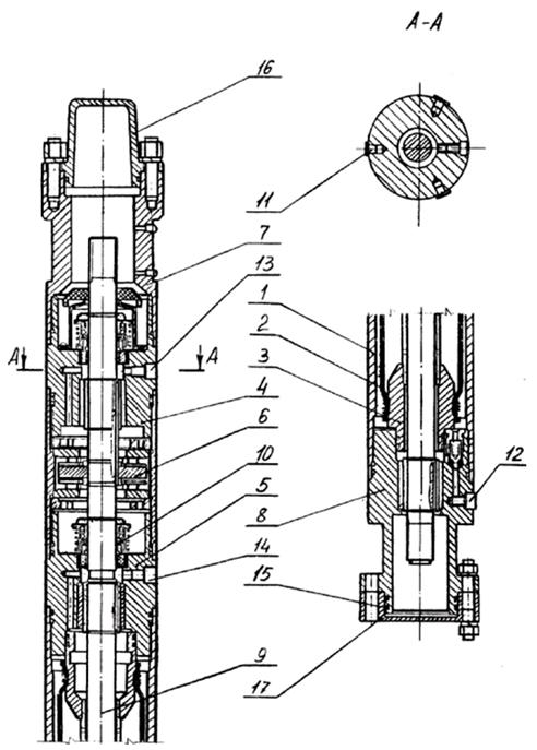
Submersible centrifugal electric pumps (PTSEN) are multistage centrifugal pumps with up to 120 stages in one block, driven by a submersible electric motor of a special design (SEM). The electric motor is fed from the surface with electricity supplied via a cable from a step-up autotransformer or transformer through a control station, in which all instrumentation and automation are concentrated. The PTSEN is lowered into the well under the calculated dynamic level, usually by 150 - 300 m. The liquid is supplied through the tubing, to outside which is attached by special belts to the electric cable. In the pump unit between the pump itself and the electric motor there is an intermediate link called a protector or hydraulic protection. The PTSEN installation (Figure 3) includes an oil-filled electric motor SEM 1; hydraulic protection link or protector 2; intake grid of the pump for fluid intake 3; multistage centrifugal pump ПЦЭН 4; tubing 5; armored three-core electrical cable 6; belts for attaching the cable to the tubing 7; wellhead fittings 8; a drum for winding a cable during tripping and storing a certain supply of cable 9; transformer or autotransformer 10; control station with automation 11 and compensator 12.
The pump, protector and electric motor are separate units connected by bolted studs. The ends of the shafts have splined connections, which are joined when assembling the entire installation. If it is necessary to lift liquid from great depths, the PTSEN sections are connected to each other so that total number steps reaches 400. The fluid sucked in by the pump sequentially passes all the steps and leaves the pump with a pressure equal to the external hydraulic resistance.
Figure 3 - General scheme well equipment installation of a submersible centrifugal pump
UTSEN are characterized by low metal consumption, a wide range of performance characteristics, both in terms of pressure and flow, a sufficiently high efficiency, the possibility of pumping large quantities liquids and a long overhaul period. It should be recalled that the average liquid supply for Russia of one UPTsEN is 114.7 t/day, and USSSN - 14.1 t/day.
All pumps are divided into two main groups; conventional and wear-resistant design. The vast majority of the operating stock of pumps (about 95%) is of conventional design.
Wear-resistant pumps are designed to work in wells, in the production of which there is a small amount of sand and other mechanical impurities (up to 1% by weight). According to the transverse dimensions, all pumps are divided into 3 conditional groups: 5; 5A and 6, which means nominal diameter casing string, (in inches), in which this pump can be run.
Group 5 has an outer case diameter of 92 mm, group 5A - 103 mm and group b - 114 mm. The speed of the pump shaft corresponds to the frequency of the alternating current in the mains. In Russia, this frequency is 50 Hz, which gives a synchronous speed (for a two-pole machine) of 3000 min-1. The PTSEN cipher contains their main nominal parameters, such as flow and pressure when operating in the optimal mode. For example, ESP5-40-950 means a group 5 centrifugal electric pump with a flow of 40 m3/day (by water) and a head of 950 m. ESP5A-360-600 means a group 5A pump with a flow of 360 m3/day and a head of 600 m.

Figure 4 - Typical characteristics of a submersible centrifugal pump
In the code of wear-resistant pumps, there is the letter I, which means wear resistance. In them, impellers are made not from metal, but from polyamide resin (P-68). In the pump housing, approximately every 20 stages, intermediate rubber-metal shaft centering bearings are installed, as a result of which the wear-resistant pump has fewer stages and, accordingly, a head.
The end bearings of the impellers are not cast iron, but in the form of pressed rings made of hardened steel 40X. Instead of textolite support washers between the impellers and guide vanes, washers made of oil-resistant rubber are used.
All types of pumps have a passport operating characteristic in the form of dependence curves H (Q) (pressure, flow), h (Q) (efficiency, flow), N (Q) (power consumption, flow). Usually these dependencies are given in the range of operating flow rates or in a slightly larger interval (Fig. 11.2).
Any centrifugal pump, including the PTSEN, can operate with a closed outlet valve (point A: Q = 0; H = Hmax) and without counterpressure at the outlet (point B: Q = Qmax; H = 0). Insofar as useful work pump is proportional to the product of the supply to the head, then for these two extreme modes of operation of the pump, the useful work will be equal to zero, and, consequently, the efficiency will be equal to zero. At a certain ratio (Q and H), due to the minimum internal losses of the pump, the efficiency reaches a maximum value of approximately 0.5 - 0.6. Typically, pumps with low flow and small diameter impellers, as well as with a large number stages have a reduced efficiency. The flow and pressure corresponding to the maximum efficiency are called the optimal operating mode of the pump. The dependence z(Q) near its maximum decreases smoothly, therefore, the operation of the PTSEN is quite acceptable under modes that differ from the optimal one in one direction or the other by some value. The limits of these deviations will depend on the specific characteristics of the PTSEN and should correspond to a reasonable decrease in the efficiency of the pump (by 3 - 5%). This determines a whole area of possible modes of operation of the PTSEN, which is called the recommended area (see Fig. 11.2, hatching).
The selection of a pump for wells essentially boils down to choosing such a standard size of the PTSEN that, when lowered into the well, it would operate under the conditions of the optimal or recommended mode when pumping a given well flow rate from a given depth.
The pumps currently produced are designed for nominal flow rates from 40 (ETsN5-40-950) to 500 m3/day (ETsN6-500-750) and heads from 450 m (ETsN6-500-450) to 1500 m (ETsN6-100- 1500). In addition, there are pumps special purpose, for example, for pumping water into reservoirs. These pumps have flows up to 3000 m3/day and heads up to 1200 m.
The head that a pump can overcome is directly proportional to the number of stages. Developed by one stage at the optimum operating mode, it depends, in particular, on the dimensions of the impeller, which in turn depend on the radial dimensions of the pump. With an outer diameter of the pump casing of 92 mm, the average head developed by one stage (when operating on water) is 3.86 m with fluctuations from 3.69 to 4.2 m. With an outer diameter of 114 mm, the average head is 5.76 m with fluctuations from 5.03 to 6.84 m.
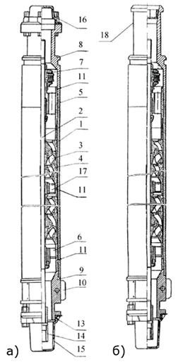
The pumping unit consists of a pump (Figure 4, a), a hydraulic protection unit (Figure 4, 6), a SEM submersible motor (Figure 4, c), a compensator (Figure 4, d) attached to the lower part of the SEM.
The pump consists of the following parts: a head 1 with a ball check valve to prevent fluid from draining from the tubing during shutdowns; the upper bearing foot of the slide 2, which partially perceives the axial load due to the pressure difference at the inlet and outlet of the pump; upper plain bearing 3 centering the upper end of the shaft; pump housing 4; guide vanes 5, which rest on each other and are kept from rotation by a common coupler in the housing 4; impellers 6; pump shaft 7, which has a longitudinal key on which impellers are mounted with a sliding fit. The shaft also passes through the guide apparatus of each stage and is centered in it by the impeller bushing, as in a bearing; lower plain bearing 8; base 9, covered with a receiving grid and having round inclined holes for supplying fluid to the lower impeller; end plain bearing 10. In pumps of early designs that are still in operation, the device of the lower part is different. Along the entire length of the base 9 is placed a gland of lead-graphite rings, separating the receiving part of the pump and the internal cavities of the engine and hydraulic protection. A three-row angular contact ball bearing is mounted below the stuffing box, lubricated with thick oil, which is under some pressure (0.01 - 0.2 MPa) in relation to the external one.
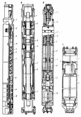
Figure 4 - The device of the submersible centrifugal unit
a - centrifugal pump; b - hydraulic protection unit; c - submersible electric motor; g - compensator
AT modern designs There is no excess pressure in the ESP in the hydraulic protection unit, therefore, there is less leakage of liquid transformer oil, with which the SEM is filled, and the need for a lead-graphite gland has disappeared.
The cavities of the engine and the receiving part are separated by a simple mechanical seal, the pressures on both sides of which are the same. The length of the pump housing usually does not exceed 5.5 m. When the required number of stages (in pumps that develop high pressures) cannot be placed in one housing, they are placed in two or three separate housings that make up independent sections of one pump, which are docked together when lowering the pump into the well
Hydroprotection unit - an independent unit attached to the PTSEN bolted connection(in Figure 4, the node, like the PTSEN itself, is shown with transport plugs sealing the ends of the nodes)
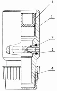
The upper end of shaft 1 is connected by a splined coupling to the lower end of the pump shaft. Light mechanical seal 2 separates the upper cavity, which can contain well fluid, from the cavity below the seal, which is filled with transformer oil, which, like the well fluid, is under pressure equal to the pressure at the pump immersion depth. Below the mechanical seal 2 there is a sliding friction bearing, and even lower - node 3 - a bearing foot that perceives the axial force of the pump shaft. The sliding foot 3 operates in liquid transformer oil.
Below is the second mechanical seal 4 for more reliable sealing of the engine. It is not structurally different from the first. Under it is a rubber bag 5 in the body 6. The bag hermetically separates two cavities: the inner cavity of the bag filled with transformer oil, and the cavity between the body 6 and the bag itself, into which the external well fluid has access through the check valve 7.
The downhole fluid through the valve 7 penetrates into the cavity of the housing 6 and compresses the rubber bag with oil to a pressure equal to the external one. Liquid oil penetrates through the gaps along the shaft to the mechanical seals and down to the PED.
Two designs of hydraulic protection devices have been developed. The hydroprotection of the main engine differs from the described hydroprotection of the G by the presence of a small turbine on the shaft, which creates high blood pressure liquid oil in the inner cavity of the rubber bag 5.
The outer cavity between the housing 6 and the bag 5 is filled with thick oil, which feeds the ball angular contact bearing PTSEN of the previous design. Thus, the hydraulic protection unit of the main engine of an improved design is suitable for use in conjunction with the PTSEN of the previous types that are widely used in the fields. Previously, hydraulic protection was used, the so-called piston-type protector, in which excess pressure on the oil was created by a spring-loaded piston. New designs of the main engine and the main engine proved to be more reliable and durable. Temperature changes in the volume of oil during its heating or cooling are compensated by attaching a rubber bag - compensator to the bottom of the PED.
To drive the PTSEN, special vertical asynchronous oil-filled bipolar electric motors (SEMs) are used. Pump motors are divided into 3 groups: 5; 5A and 6.
Since, unlike the pump, the electric cable does not pass along the motor housing, the diametrical dimensions of the SEMs of these groups are slightly larger than those of the pumps, namely: group 5 has a maximum diameter of 103 mm, group 5A - 117 mm and group 6 - 123 mm.
The marking of the SEM includes the rated power (kW) and diameter; for example, PED65-117 means: a submersible electric motor with a power of 65 kW with a housing diameter of 117 mm, i.e. included in group 5A.
Small allowable diameters and high power (up to 125 kW) make it necessary to make engines of great length - up to 8 m, and sometimes more. Top part The PED is connected to the lower part of the hydraulic protection assembly using bolted studs. Shafts are joined by spline couplings.
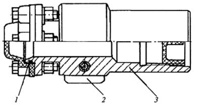
The upper end of the PED shaft is suspended on the sliding heel 1, which operates in oil. Below is the node cable entry 2. This assembly is usually a male cable connector. This is one of the most vulnerable places in the pump, due to the violation of the insulation of which the installations fail and require lifting; 3 - lead wires of the stator winding; 4 - upper radial sliding friction bearing; 5 - section of the end ends of the stator winding; 6 - stator section, assembled from stamped transformer iron plates with grooves for pulling stator wires. The stator sections are separated from each other by non-magnetic packages, in which the radial bearings 7 of the motor shaft 8 are strengthened. The lower end of the shaft 8 is centered by the lower radial sliding friction bearing 9. The SEM rotor also consists of sections assembled on the motor shaft from stamped plates of transformer iron. Aluminum rods are inserted into the slots of the squirrel-wheel type rotor, shorted by conductive rings, on both sides of the section. Between the sections, the motor shaft is centered in bearings 7. A hole with a diameter of 6–8 mm passes through the entire length of the motor shaft for oil to pass from the lower cavity to the upper one. Along the entire stator there is also a groove through which oil can circulate. The rotor rotates in liquid transformer oil with high insulating properties. In the lower part of the PED there is a mesh oil filter 10. The head 1 of the compensator (see Fig. 11.3, d) is attached to the lower end of the PED; bypass valve 2 serves to fill the system with oil. The protective casing 4 in the lower part has holes for transferring the external fluid pressure to the elastic element 3. When the oil cools, its volume decreases and the well fluid through the holes enters the space between the bag 3 and the casing 4. When heated, the bag expands, and the fluid through the same holes comes out of the casing.
PEDs used for the operation of oil wells usually have capacities from 10 to 125 kW.
To maintain reservoir pressure, special submersible pumping units are used, equipped with 500 kW PEDs. The supply voltage in the SEM ranges from 350 to 2000 V. At high voltages, it is possible to proportionally reduce the current when transmitting the same power, and this allows you to reduce the cross section conductive cores cable, and consequently, the transverse dimensions of the installation. This is especially important for high power motors. SEM rotor slip nominal - from 4 to 8.5%, efficiency - from 73 to 84%, allowable temperatures environment- up to 100 °С.
During the operation of the PED, a lot of heat is released, therefore, for normal operation engine needs cooling. Such cooling is created due to the continuous flow of formation fluid through the annular gap between the motor housing and the casing string. For this reason, wax deposits in the tubing during pump operation are always significantly less than during other methods of operation.
AT working conditions there is a temporary blackout of the power lines due to a thunderstorm, a wire break, due to their icing, etc. This causes the UTSEN to stop. In this case, under the influence of the liquid column flowing from the tubing through the pump, the pump shaft and the stator begin to rotate in the opposite direction. If at this moment the power supply is restored, the SEM will begin to rotate in the forward direction, overcoming the inertia force of the liquid column and the rotating masses.
Starting currents in this case may exceed the permissible limits, and the installation will fail. To prevent this from happening, a ball check valve is installed in the discharge part of the PTSEN, which prevents the liquid from draining from the tubing.
The check valve is usually located in the pump head. Availability check valve complicates the rise of the tubing when repair work, since in this case the pipes are lifted and unscrewed with liquid. In addition, it is dangerous in terms of fire. To prevent such phenomena, a drain valve is made in a special coupling above the check valve. In principle, the drain valve is a coupling, in the side wall of which a short bronze tube is inserted horizontally, sealed from the inner end. Before lifting, a short metal dart is thrown into the tubing. The blow of the dart breaks off the bronze tube, as a result of which the side hole in the sleeve opens and the liquid from the tubing drains.
Other devices have also been developed for draining the liquid, which are installed above the PTSEN check valve. These include the so-called prompters, which make it possible to measure the annulus pressure at the pump descent depth with a downhole pressure gauge lowered into the tubing, and establish communication between the annular space and the measuring cavity of the pressure gauge.
It should be noted that the engines are sensitive to the cooling system, which is created by the fluid flow between the casing string and the SEM body. The speed of this flow and the quality of the liquid affect temperature regime PED. It is known that water has a heat capacity of 4.1868 kJ/kg-°C, while pure oil is 1.675 kJ/kg-°C. Therefore, when pumping out watered well production, the conditions for cooling the SEM are better than when pumping clean oil, and its overheating leads to insulation failure and engine failure. Therefore, the insulating qualities of the materials used affect the duration of the installation. It is known that the heat resistance of some insulation used for motor windings has already been brought up to 180 °C, and operating temperatures up to 150 °C. To control the temperature, simple electrical temperature sensors transmitting information about the temperature of the SEM to the control station via the power electrical cable without the use of an additional core. Similar devices are available for transmitting constant information about the pressure at the pump intake to the surface. In case of emergency conditions, the control station automatically switches off the SEM.
The SEM is powered by electricity through a three-core cable, which is lowered into the well in parallel with the tubing. The cable is attached to the outer surface of the tubing with metal belts, two for each pipe. The cable works in difficult conditions. Its upper part is in a gaseous environment, sometimes under significant pressure, the lower part is in oil and is subjected to even greater pressure. When lowering and retrieving the pump, especially in deviated wells, the cable is subjected to strong mechanical influences(clamps, friction, jamming between the string and tubing, etc.). The cable transmits electricity at high voltages. The use of high voltage motors makes it possible to reduce the current and hence the cable diameter. However, the cable for powering a high-voltage motor must also have a more reliable, and sometimes thicker, insulation. All cables used for UPTsEN are covered with elastic galvanized steel tape on top to protect against mechanical damage. The need to place the cable along the outer surface of the PTSEN reduces the dimensions of the latter. Therefore, a flat cable is laid along the pump, having a thickness of about 2 times less than the diameter of a round one, with the same cross-sections of conductive cores.
All cables used for UTSEN are divided into round and flat. Round cables have rubber (oil-resistant rubber) or polyethylene insulation, which is displayed in the code: KRBK means armored rubber round cable or KRBP - rubber armored flat cable. When using polyethylene insulation in the cipher, instead of the letter P, P is written: KPBK - for a round cable and KPBP - for a flat one.
The round cable is attached to the tubing, and the flat cable is attached only to the lower pipes of the tubing string and to the pump. The transition from a round cable to a flat cable is spliced by hot vulcanization in special molds, and if such splicing is of poor quality, it can serve as a source of insulation failure and failures. AT recent times pass only to flat cables running from the SEM along the tubing string to the control station. However, the manufacture of such cables is more difficult than round ones (Table 11.1).
There are some other types of polyethylene insulated cables not mentioned in the table. Cables with polyethylene insulation are 26 - 35% lighter than cables with rubber insulation. Rubber insulated cables are designed for use at rated voltage electric current not more than 1100 V, at ambient temperatures up to 90 °C and pressure up to 1 MPa. Cables with polyethylene insulation can operate at voltages up to 2300 V, temperatures up to 120 °C and pressures up to 2 MPa. These cables are more resistant to gas and high pressure.
All cables are armored with corrugated galvanized steel tape for strength.
The primary windings of three-phase transformers and autotransformers are always designed for the voltage of the commercial power supply network, i.e. 380 V, to which they are connected through control stations. The secondary windings are designed for the operating voltage of the respective motor to which they are connected by cable. These operating voltages in various PEDs vary from 350V (PED10-103) to 2000V (PED65-117; PED125-138). To compensate for the voltage drop in the cable from the secondary winding, 6 taps are made (in one type of transformer there are 8 taps), which allow you to adjust the voltage at the ends of the secondary winding by changing the jumpers. Changing the jumper by one step increases the voltage by 30 - 60 V, depending on the type of transformer.
All transformers and autotransformers are non-oil filled with air-cooled closed with a metal casing and designed for installation in a sheltered place. They are completed with underground installation, so their parameters correspond to this SEM.
Recently, transformers have become more widespread, as this allows you to continuously control the resistance of the secondary winding of the transformer, cable and stator winding of the SEM. When the insulation resistance drops to the set value (30 kOhm), the unit automatically switches off.
With autotransformers having a direct electrical connection between the primary and secondary windings, such insulation control cannot be carried out.
Transformers and autotransformers have an efficiency of about 98 - 98.5%. Their mass, depending on the power, ranges from 280 to 1240 kg, dimensions from 1060 x 420 x 800 to 1550 x 690 x 1200 mm.
The operation of the UPTsEN is controlled by the control station PGH5071 or PGH5072. Moreover, the control station PGH5071 is used for autotransformer power supply of the SEM, and PGH5072 - for transformer. Stations PGH5071 provide instant shutdown of the installation when the current-carrying elements are shorted to the ground. Both control stations provide the following possibilities for monitoring and controlling the operation of the UTSEN.
1. Manual and automatic (remote) switching on and off of the unit.
2. Automatic switching on of the installation in the self-start mode after the restoration of the voltage supply in the field network.
3. automatic operation installations in periodic mode (pumping out, accumulation) according to the established program with a total time of 24 hours.
4. Automatic switching on and off of the unit depending on the pressure in the discharge manifold when automated systems group collection of oil and gas.
5. Instantaneous shutdown of the installation in case of short circuits and overloads in current strength by 40% exceeding the normal operating current.
6. Short-term shutdown for up to 20 s when the SEM is overloaded by 20% of the nominal value.
7. Short-term (20 s) shutdown in case of failure of the fluid supply to the pump.
The doors of the control station cabinet are mechanically interlocked with a switch block. There is a trend towards switching to non-contact, hermetically sealed control stations with semiconductor elements, which, as experience has shown, are more reliable, not affected by dust, moisture and precipitation.
Control stations are intended for installation in shed-type premises or under a canopy (in the southern regions) at an ambient temperature of -35 to +40 °C.
The mass of the station is about 160 kg. Dimensions 1300 x 850 x 400 mm. The UPTsEN delivery set includes a drum with a cable, the length of which is determined by the customer.
During the operation of the well, for technological reasons, the depth of the pump suspension has to be changed. In order not to cut or build up the cable with such suspension changes, the cable length is taken according to the maximum suspension depth. this pump and at shallower depths, its excess is left on the drum. The same drum is used for winding the cable when lifting the PTSEN from the wells.
With a constant suspension depth and stable pumping conditions, the end of the cable is tucked into the junction box, and there is no need for a drum. In such cases, during repairs, a special drum is used on a transport trolley or on a metal sledge with a mechanical drive for constant and uniform pulling of the cable extracted from the well and winding it onto the drum. When the pump is lowered from such a drum, the cable is evenly fed. The drum is electrically driven with reverse and friction to prevent dangerous tensions. At oil producing enterprises with a large number of ESPs, a special ATE-6 transport unit based on the KaAZ-255B cargo all-terrain vehicle is used to transport a cable drum and other electrical equipment, including a transformer, pump, engine and hydraulic protection unit.
For loading and unloading the drum, the unit is equipped with folding directions for rolling the drum onto the platform and a winch with a pulling force on the rope of 70 kN. The platform also has a hydraulic crane with a lifting capacity of 7.5 kN with an outreach of 2.5 m.
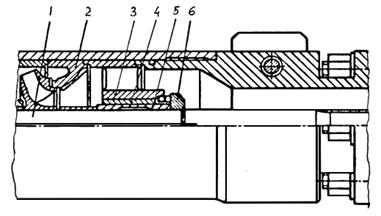
Typical wellhead fittings equipped for PTSEN operation (Figure 5) consist of a crosspiece 1, which is screwed onto the casing string.

Figure 5 - Wellhead fittings equipped with PTSEN
The cross has a detachable insert 2, which takes the load from the tubing. A seal made of oil-resistant rubber 3 is applied to the liner, which is pressed by a split flange 5. Flange 5 is pressed by bolts to the flange of the cross and seals the cable outlet 4.
The fittings provide for the removal of annular gas through the pipe 6 and the check valve 7. The fittings are assembled from unified units and stopcocks. It is relatively easy to rebuild for wellhead equipment when operating with sucker rod pumps.
The operation of wells with installations of submersible centrifugal pumps (ESPs) is currently the main method of oil production in Russia. These installations extract about two thirds of the total annual oil production in our country to the surface.
Electrocentrifugal borehole pumps(ESP) belong to the class of dynamic vane pumps, characterized by high flows and lower heads compared to positive displacement pumps.
The delivery range of downhole electric centrifugal pumps is from 10 to 1000 m 3 /day and more, the head is up to 3500 m. high efficiency among all mechanized methods of oil extraction. In the flow range from 50 to 300 m 3 /day, the pump efficiency exceeds 40%.
The purpose of electric centrifugal borehole pumps is to extract oil from a well with a water content of up to 99%, a mechanical impurities content of up to 0.01% (0.1 g / l) with a hardness of up to 5 points according to Mohs; hydrogen sulfide up to 0.001%, gas content up to 25%. In the corrosion-resistant design, the content of hydrogen sulfide can be up to 0.125% (up to 1.25 g/l). In the wear-resistant design, the content of mechanical impurities is up to 0.5 g/l. The allowable rate of curvature of the wellbore is up to 20 by 10 m. The angle of deviation of the wellbore axis from the vertical is up to 400.
The advantage of the ESP is the great opportunities for automation of work and remote control condition compared to rod installations. In addition, ESPs are less affected by borehole curvature.
The disadvantages of electric centrifugal pumps is the deterioration of performance in a corrosive environment, with sand removal, in conditions high temperature and high gas factor, decrease in operating parameters with an increase in the viscosity of the liquid (with a viscosity of more than 200 cP, the operation of the ESP becomes impossible).
The main manufacturers of submersible centrifugal pumps in Russia are the Almetyevsk Pumping Plant (JSC ALNAS), the Lebedyansky Machine-Building Plant (JSC LEMAZ), the Moscow plant Borets. Interesting developments are also offered by other organizations, for example, the Perm plant JSC Novomet, which manufactures original stages of submersible centrifugal pumps using the powder metallurgy method.
ESP units in Russia are manufactured in accordance with technical specifications, while abroad they are manufactured in accordance with API requirements.
The most famous foreign manufacturers ESP units - REDA, Centrilift, ODI and ESP (USA). AT last years ESP manufacturers from the People's Republic of China (Temtext) are also very active.
In the data guidelines the main structural schemes of ESPs, features of their design and principle of operation are given.
For self check acquired knowledge at the end of the guidelines is a list of control questions.
The purpose of this laboratory work– study of the design of a submersible centrifugal pump.
2. Theory
2.1. General installation diagram of a submersible electric centrifugal pump
To date, a large number of different schemes and modifications of ESP units have been proposed. Figure 2.1 shows one of the schemes for equipping a production well with a submersible centrifugal electric pump.
Rice. 2.1. Scheme of installation of a submersible centrifugal pump in a well
The diagram shows: compensator 1, submersible motor (SEM) 2, protector 3, intake screen 4 with gas separator 5, pump 6, fishing head 7, pump check valve 8, drain valve 9, tubing string (tubing) 10, bend 11, flow line 12, wellhead check valve 13, pressure gauges 14 and 16, wellhead fittings 15, cable line 17, connecting ventilation box 18, control station 19, transformer 20, dynamic liquid level in the well 21, belts 22 for attaching the cable line to the tubing and pumping unit and the production string of the well 23.
During operation of the unit, pump 6 pumps liquid from the well to the surface through tubing 10. Pump 6 is driven by a submersible electric motor 2, the electric power to which is supplied from the surface via cable 17. Motor 2 is cooled by the flow of well products.
Ground electrical equipment - control station 19 with transformer 20 - is designed to convert the voltage of the field electrical network to a value that provides the optimal voltage at the input to the electric motor 2, taking into account losses in the cable 17, and
Figure 1.1 - Scheme of installation of a submersible centrifugal pump in a well.
also for work management submersible installation and its protection under abnormal conditions.
The maximum content of free gas at the inlet to the pump, allowed by domestic technical conditions, is 25%. If there is a gas separator at the ESP intake, the allowable gas content increases to 55%. Foreign manufacturers of ESPs recommend the use of gas separators in all cases where the inlet gas content is more than 10%.
2.2. Designs of the main components and parts of the pump
The main elements of any centrifugal pump are impellers, shaft, housing, radial and axial bearings (bearings), seals that prevent internal and external fluid leakage.
Electric centrifugal borehole pumps - multistage. The impellers are arranged in series on the shaft. Each wheel has a guide vane, in which the speed energy of the liquid is converted into pressure energy, with its subsequent direction to the next wheel. The impeller and guide vane form the pump stage.
In multistage pumps with a series arrangement of wheels, units are provided for unloading axial forces.
2.2.1. Pump stages
The pump stage is the main working body of a downhole centrifugal pump, through which energy is transferred from the fluid pump. The stage consists (Fig. 2.2) of the impeller 3 and the guide vane 1.

Rice. 2.2. ESP stage
5 - lower support washer; 6 - protective sleeve;
7 - upper support washer; 8 - shaft
The pressure of one stage is from 3 to 7 m of water column. A small amount of pressure is determined by the small value of the outer diameter of the impeller, limited by the inner diameter of the casing string. The required pump head values are reached sequential installation impellers and guide vanes.
The steps are placed in the bore of the cylindrical body of each section. One section can accommodate from 39 to 200 stages (the maximum number of stages in the pumps reaches 550 pieces).
To be able to assemble an ESP with such a number of stages and unload the shaft from axial force, a floating impeller is used. Such a wheel is not fixed on the shaft in the axial direction, but moves freely in the gap limited by the bearing surfaces of the guide vanes. A feather key keeps the wheel from turning.
The individual axial support of each stage consists of a support shoulder of the guide vane of the previous stage and an anti-friction wear-resistant (textolite) washer pressed into the impeller bore (pos.5, Fig. 2.2). This support (heel) is also the front wheel seal, which reduces internal leakage in the pump.
In modes approximately 10% higher than the flow corresponding to zero axial force, the impeller can “float” - move up. To ensure a reliable stop for the wheel, an upper axial support is provided. On the upper individual support, the impeller can also operate during short-term starting modes. The upper support consists of a support collar on the guide vane and a washer pressed into the bore of the impeller (pos.7, Fig. 2.2).
The main elements of the pump stage can have different designs. In accordance with this, the stages and, in fact, the pumps are classified as follows.
1. According to the design of the vane apparatus of the impeller:
With cylindrical (radial) blades (Fig. 2.3, a) and with oblique-cylindrical (radial-axial) blades (Fig. 2.3, b).
In steps with radial guide vanes, the transfer channels are arranged radially. Hydraulically, they are more perfect, but the nominal flow is limited to 125 m 3 / day in pumps with an outer diameter of 86 and 92 mm and up to 160 m 3 / day in pumps with an outer diameter of 103 mm and 114 mm.
For impellers with inclined-cylindrical blades, the blades enter the region of rotation from the axial direction to the radial direction, which leads to an inclined position of their leading edge with respect to the pump axis. The value of the coefficient of speed of such wheels is on the extreme right border of high-speed pumps, approaching the diagonal pumps. Delivery in such steps is higher.
2. According to the design of the flow channels of the guide apparatus, the stages can be with radial and “axial” flow channels.
Step designs with radial and axial guide vanes are shown in fig. 2.3 a, b.

Rice. 2.3. Stage with impeller and guide vane
(a) radial design and (b) radial-axial design
guide apparatus; 4 - support washers; 5 - shaft; 6 - key
Radial guide vanes have a radial arrangement of flow channels. A stage with such guide vanes is hydraulically more perfect, has a simpler geometry, is convenient in production, but has a low flow rate (20 ... 40 m 3 / day).
The stage with an “axial” guide vane is named conditionally, since in it the arrangement of channels that convert the kinetic energy of the flow into potential energy approaches the axial one. A stage with an axial guide vane provides a large flow (40...1000 m 3 /day), a simpler geometry and has been widely used in the manufacture of domestic designs of submersible pumps, practically replacing the "radial" stage, which is no longer produced at present.
2. According to the method of installing impellers on the shaft:
Stages with floating impellers;
· steps with rigid wheels (used in foreign designs).
3. According to the method of unloading from axial forces:
stages with impellers not unloaded from axial force (Fig. 2.1, 2.2);
· stages unloaded from axial force with the help of an unloading chamber from the side of the rear (main) disk (Fig. 2.4). The chamber is made using a gap seal and through holes in the main drive. This method is used in steps with inclined cylindrical blades.
· stages unloaded from axial force by the implementation of radial impellers on the outer side of the rear disk (Fig. 2.5). Radial impellers on the rear disc reduce the pressure acting on it and are used mainly in cylindrical wheels. Wheels, in this case, are called centrifugal-vortex.
Centrifugal vortex wheels were developed and manufactured by Novomet. For their manufacture, the method of powder metallurgy is used. The use of centrifugal-vortex wheels has a number of advantages: the stage pressure increases by 15 ... 20%; the pump can be used to lift liquids with a high gas content (up to 35% by volume).
Stages with unloaded impellers have an increased service life of the individual lower impeller support. But they have a complex technology and increased labor intensity of manufacture. In addition, during operation, a functional failure of the unloading method using the unloading chamber can occur if the unloading holes are clogged and the upper seal of the impeller is worn.
![]()
Rice. 2.4. Construction of stages with unloaded impeller

Rice. 2.5. Stages of the centrifugal vortex pump manufactured by Novomet
apparatus; 6 - lower support washer; 7 - upper support washer;
8 - pump housing
4. According to the creation of a support for wheels of a floating type, steps can be of a single-support structure and a double-support structure.
The steps of a single-support structure have one individual lower support - the heel - from the side of the front disk.
Double-support stages have an additional axial support through a pressed-in textolite ring on the impeller hub at the inlet and the end flange of the guide vane (Fig. 2.6). The additional support strengthens the axial support and the interstage sealing of the steps.

Rice. 2.6. Two-bearing stage of a centrifugal pump
disk; 4 - the main ring of the front disk; 5 – a ring of a back disk
The advantages of a two-support design are an increased resource of the main lower step support, more reliable isolation shaft from abrasive and corrosive flowing liquid, increased service life and greater rigidity of the pump shaft due to increased axial lengths of the interstage seals, which also serve as radial bearings in the ESP.
The disadvantage of two-bearing steps is the increase in labor intensity in manufacturing.
4. According to the execution of the stage, there can be:
normal execution (ESP);
wear-resistant (ECNI);
Corrosion-resistant (ETsNK).
Stages in pumps of different designs differ from each other in the materials of working bodies, friction pairs and some structural elements.
Steps in a corrosion-resistant and wear-resistant design, as a rule, have two individual lower supports and an elongated hub on the side of the rear disk, which closes the shaft gap between the wheels from wear (Fig. 2.6).
In the usual version, for the manufacture of impellers and guide vanes, mainly modified cast iron is used, in the friction pair of the upper and lower main support - textolite-cast iron, additional support - textolite-cast iron or rubber-cast iron. In corrosion-resistant design, wheels and guide vanes can be made of niresist cast iron. Increased wear resistance - from wear-resistant cast iron, friction pair in the lower main bearing - rubber-silicon graphite, additional support - rubber-cast iron, upper bearing - textolite-cast iron. Cast iron wheels can also be replaced with plastic wheels made of polyamide resin or carbon fiber, which are resistant to free abrasive wear and do not swell in water (experience has shown that they are less efficient in wells with a high oil content).
The traditional technology for manufacturing steps by Russian manufacturers is casting. Roughness of castings is within Rz 40…80 µm (GOST 2789-83).
Lower roughness (Rz 10) allows obtaining blanks manufacturing technology by powder metallurgy, developed by Novomet JSC. The use of this technology made it possible to significantly increase the efficiency of the stages and produce more complex structures impellers (centrifugal vortex wheels).
2.2.2. Pump bearing units
Bearing units of a downhole centrifugal electric pump are one of the main units that determine the durability and performance of the pumping unit. They work in the medium of the pumped liquid and are plain bearings.
For the perception of axial forces acting on the shaft and radial loads in the ESP, axial and radial bearings are used, respectively.
2.2.2.1. Axial bearings
The axial force acting on the rotor is created from its own weight, from the pressure drop on the shaft end, as well as from the pressure drop and the difference in the areas of the rear and front discs of impellers with a hard fit on the shaft or floating wheels stuck to the shaft during operation.
A thrust bearing that receives axial force is installed either directly in the pump - in the upper part of the section or module-section (domestic designs), or in the hydraulic protection of the pump (foreign designs).

Rice. 2.6 - Thrust bearing of pump ETsNM(K)
1 - hydrodynamic heel; 2, 3 - smooth washers; 4, 5 - rubber washers -
shock absorbers; 6 - upper support (thrust bearing); 7 - lower support (thrust bearing);
10 - fixed sleeve of the upper radial bearing; 11 - rotating sleeve
upper radial bearing
The thrust bearing in domestic designs in the usual version (Fig. 2.7) consists of a ring (hydrodynamic heel) 1 with segments on both planes, installed between two smooth washers 2 and 3.
The segments on the washer of the hydrodynamic anvil (moving part of the bearing) 1 are made with an inclined surface with an angle and a flat area of length (0.5…0.7)· (where is the full length of the segment). The segment width is (1…1.4) L. To compensate for inaccuracies in manufacturing and the perception of shock loads, elastic rubber shock absorber washers 4, 5 are placed under the smooth rings, pressed into the upper 6 and lower 7 supports (fixed bearings). The axial force from the shaft is transmitted through the spring ring 8 of the shaft support and the spacer sleeve 9 to the thrust bearing.
The hydrodynamic heel is made with radial grooves, a bevel and a flat part on the friction surface against the thrust bearing. It is usually made of belting (technical fabric with large cells), impregnated with graphite with rubber and vulcanized in a mold. Smooth washers are made of steel 40X13.
When the heel rotates, the liquid goes from the center to the periphery along the grooves, gets under the bevel and is injected into the gap between the flat parts of the heel and the heel. Thus, the thrust bearing slides over the liquid layer. Such fluid friction in the operating mode of the heel provides a low coefficient of friction, insignificant energy losses for friction in the heel, low wear of the heel parts with sufficient axial force that it perceives.

7 - lower sleeve
2.2.3. Radial supports

1 - shaft; 2 - pump stage; 3 - bearing hub;
2.2.4. Shaft
2.2.5. Frame


2.3.2.1. electric motor
![]()
2.3.2.2. Hydroprotection

Rice. 3.17. Compensator
Rice. 2.18. Tread
2.3.2.3. cable line


Rice. 2. 20. Check valve
Rice. 2.21. Bleed valve
2.4. Designation of ESP and ESP
![]() ,
,
where is the diameter of the pump casing;
Motor housing diameter;

Table 2.1
|
Indicators |
ESP Group |
||||||||||||||||||||||||||
|
Pump outer diameter, mm The outer diameter of the SEM, grooves, falls under the bevel and is injected into the gap between the flat parts of the thrust bearing and the heel. Thus, the thrust bearing slides over the liquid layer. Such fluid friction in the operating mode of the heel provides a low coefficient of friction, insignificant energy losses for friction in the heel, low wear of the heel parts with sufficient axial force that it perceives. Thrust bearings allow specific load up to 3 MPa. In the axial bearings of wear-resistant pumps, more wear-resistant materials of rubbing pairs are used: siliconized graphite SG-P on siliconized graphite SG-P or silicon carbide on silicon carbide. A variant of the design of the thrust bearing in wear-resistant pumps is shown in fig. 2.8.
Rice. 2.8. Axial bearing wear-resistant pump 1 - top support; 2 - rubber washer; 3 – upper thrust bearing; 4 - bottom thrust bearing; 5 - lower support; 6 – top sleeve; 7 - lower sleeve 2.2.3. Radial supportsRadial loads that occur during pump operation are perceived by radial plain bearings operating in the well production flow. In the usual design, radial bearings are located in the upper and lower parts of the housing of each section or each module-section of the pump. In wear-resistant pumps, to limit the buckling of the shaft, intermediate radial supports are used, which, depending on the type of pump, are mounted every 16-25 steps (at a distance of 650 to 1000 mm) together with guide vanes. On fig. 2.7, 2.9, 2.10 show the designs of the upper, lower and intermediate radial bearings, respectively. The radial bearing (Fig. 2.9) is a cylindrical housing with axial holes for the passage of the flow of pumped liquid and a hub 3, inside which a bushing 4 is pressed. The contact pair in the bearing is a fixed bushing 4 and a movable bushing 5. Material: steel 40X13, brass L63.
Rice. 2.8. Lower radial pump bearing assembly 1 - shaft; 2 - pump stage; 3 - bearing hub; 4 - hub sleeve; 5 - shaft sleeve; 6 - support washer The intermediate bearing (Fig. 2.10) consists of a cylindrical housing with axial channels for the passage of fluid flow and a cylindrical hub 3, inside which is fixed a sleeve 4 made of oil-resistant rubber. The inner surface has longitudinal channels that ensure the passage of fluid between the shaft and the sleeve for lubricating the bearing assembly. Shaft sleeve 5 is made of siliconized graphite SG-P or silicon carbide.
Rice. 2.10. Intermediate radial bearing unit 1 - shaft; 2 - pump stage; 3 - bearing hub; 4 - hub sleeve; 5 - shaft sleeve. In addition to the main radial bearings, brass bushings are installed on the shaft between the impellers, which, rotating in the holes of the guide vanes, also serve as radial plain bearings in each pump stage. 2.2.4. ShaftThe ESP pump shaft is assembled, connected at the ends with splined couplings at the junctions of sections and modules. The shaft and couplings are made from bars with a special surface finish. Corrosion-resistant high-strength steel is used as materials for bars. To transmit torque to the impellers, a keyed connection is used. A common keyway (groove) is milled on the shaft, into which neatly drawn bars of a square key made of brass or steel are placed. The shaft ends are in radial plain bearings. 2.2.5. FrameThe pump housing is a cylindrical pipe that combines the components and elements of the pump and forms its sections (in sectional pumps) or modules (in modular pumps). In accordance with the design scheme of the pump, sections or modules are connected to each other using a flange connection or a flange-to-body connection. Housings are made from mild steel 2.3. Basic schemes and composition of submersible electric centrifugal pumping unitsDownhole electric centrifugal unit consists of submersible pump, electric motor and hydraulic protection, having different design schemes. The main ones are listed below. 2.3.1. Submersible centrifugal pumpThe submersible centrifugal pump is made in a sectional (ETsN) or modular (ETsNM) design. The sectional pump (ESP), in general, contains a lower section with a receiving grid (Fig. 2.11), a middle section and an upper section with a fishing head (Fig. 2.12), and there may be several middle sections. Widely used are options for completing pumps in the middle section with an additional input module - a receiving grid - instead of the lower section (Fig. 2.13), as well as a head module - instead of the upper section. In this case, the pumps are called modular (ETsNM type). In cases where it is required to eliminate the harmful effect of free gas on the operation of the pump, a gas separator is installed instead of the inlet module. The lower section (Fig. 2.11) consists of a body 1, a shaft 2, a package of stages (impellers 3 and guide vanes 4, an upper bearing 5, a lower bearing 6, an upper axial support 7, a head 8, a base 9, two ribs 10 for protection cable, rubber rings 11, receiving grid 12, spline coupling 14, covers 15, 16 and intermediate bearings 17. Impellers and guide vanes are installed in series. The guide vanes are pulled together by the upper bearing and the base in the housing and are stationary during operation. The impellers are mounted on a shaft which rotates them through a key. The upper, intermediate and lower bearings are the radial bearings of the shaft, and the upper axial bearing perceives the loads acting along the shaft axis. Rubber rings 11 seal the internal cavity of the section against leakage of the pumped liquid. Spline couplings 14 are used to transmit rotation from one shaft to another. For the period of transportation and storage, the sections are closed with covers 15 and 16. The ribs 10 are designed to protect the electric cable located between them from mechanical damage when lowering and raising the pump. On fig. 2.12 shows the middle and upper sections of the pump (the designation of positions here is the same as in Fig. 2.11). The rubber ring 13 seals the connection between the sections. The upper section of the pump ends with a fishing head 18. Shown in Fig. 2.13 the input module is used to receive and coarse cleaning from mechanical impurities of pumped products. The inlet module consists of a base 1 with holes for the passage of well products, a shaft 2, a receiving grid 3 and a splined coupling 4. The base is equipped with plain bearings of the shaft and pins 5, with which the module is attached with the upper end to the pump section, and with the lower flange - to protector. Packing covers 6 and 7 are used for storage and transportation of the input module. To increase the allowable gas content of oil raised to the surface and increase the suction capacity in the ESP, the following methods are used: · the use of separators of various designs at the inlet, where the separation of gas occurs; installation of dispersing devices at the intake, where gas inclusions are crushed and a homogeneous liquid is prepared; The use of combined “stage” pumps (the first stages have a larger flow area - they are designed for a large flow); Russian manufacturers produce gas separators in accordance with normative documents types: pump modules - MNG and MNGK gas separators; pumping modules - gas separators Lyapkov MN GSL; pump gas separator modules MNGB5 (manufactured by OAO Borets). By circuit diagram these gas separators are centrifugal. They are separate pump modules, mounted in front of the package of steps of the lower section of the pump by means of flange connections. Shafts of sections or modules are connected by spline couplings. Rice. 2.11. Lower section of the pump 5 - upper bearing; 6 - lower bearing; 7 - upper axial support; 8 - head; 9 - base, 10 - two ribs to protect the cable; 11.13 - rubber rings; 12 - receiving grid; 14 - slotted coupling; 15.16 - covers; 17 - intermediate bearings
Rice. 2.12. Middle (a) and upper (b) sections of the pump.
Rice. 2.13. Pump input module 1 - base; 2 - shaft; 3 - bearing sleeve; 4 - grid; 5 - protective sleeve; 6 - slotted sleeve; 7 - hairpin
Fig. 2.14. Pump head module 1 - sealing ring; 2 - rib; 3 - body The use of gas separators at the inlet makes it possible to increase the gas content up to 50%, and in some cases up to 80% (pump module - gas separator MN GSL5, developed by Lebedyansky Machine-Building Plant JSC). On fig. 2.15 shows a gas separator of the MN(K)-GSL type (in the designation "K" - corrosion-resistant version). The separator consists of a tubular body 1 with a head 2, a base 3 with a receiving grid and a shaft 4 with working bodies located on it. Two groups of cross channels 5, 6 for gas and liquid are made in the head and a radial bearing sleeve 7 is installed. At the base there is a cavity closed with a mesh with channels 8 for receiving a gas-liquid mixture, a thrust bearing 9 and a radial bearing sleeve 10. Heel 11, auger 12, axial impeller 13 with a supercavitating blade profile, separators 14 and bushings of radial bearings 15 are placed on the shaft. A sleeve guide grate is placed in the housing.
Rice. 2.15. MN(K)-GSL type gas separator The gas separator works as follows: the gas-liquid mixture enters through the grid and the holes of the inlet module to the screw and then to the working bodies of the gas separator. Due to the acquired pressure, the GLS enters the rotating chamber of the separator, equipped with radial fins, where the gas is separated from the liquid under the action of centrifugal forces. Further, the liquid from the periphery of the separator chamber enters through the channels of the sub to the pump intake, and the gas is discharged through the inclined holes into the annulus. In addition to the modular design, gas separators can be built into the lower section of the pump (JSC Borets). Dispersants of the MNDB5 type are produced in a modular design (manufactured by OAO Borets). They are installed at the pump inlet instead of the inlet module. The maximum allowable content of free gas at the inlet to the disperser at maximum supply is 55% by volume. When the flow of the gas-liquid mixture passes through the disperser, its uniformity and degree of grinding increase. gas inclusions, thereby improving the performance of the centrifugal pump. Instead of the input module, gas separator-dispersant modules MNGDB5 manufactured by OAO Borets can also be installed. The maximum content of free gas at the inlet to the gas separator-disperser at maximum supply is 68% by volume. It should be noted that modular principle ESP layout, adopted by the domestic pump industry in the late 1980s, is currently being sharply criticized by some consumers and manufacturers of submersible pumping units. This is mainly due to the fact that with modular pumps, the number of flange connections between individual modules (sections, inlet module, fishing head, etc.) increases. In a number of cases, this leads to a decrease in the time between failures of the ESP, which is most pronounced in those oil-producing areas where a significant proportion of failures is occupied by the dismemberment and flights of installations to the bottom. Therefore, ESP manufacturers are currently completing installations in accordance with the wishes of customers, and different pump designs can be found in the fields. For example, the receiving grid can be made as a separate module (Fig. 2.13), or it can be installed directly in the lower section of the pump (Fig. 2.11), which reduces the number of flange connections. Similarly, the fishing head of the pump can be a separate module (Fig. 2.14), or it can be built into the upper section of the pump (Fig. 2.12 b), etc. 2.3.2. Submersible motor with hydraulic protection2.3.2.1. electric motorThe main type of submersible electric motors driving a submersible centrifugal pump are asynchronous oil-filled motors with squirrel-cage rotors. At a current frequency of 50 Hz, the synchronous frequency of rotation of their shaft is 3000 min -1. Motor power reaches 500 kW, voltage 400…3000 V, operating current 10…100 A. Electric motors with power from 12 to 70 kW (Fig. 2.16) are single-section and consist of a stator 1, a rotor 2, a head 3, a base 4 and a current lead assembly 5.
Rice. 2.16. Single section submersible motor The stator is made of a pipe into which a magnetic circuit is pressed, made of sheet electrical steel. The stator is magnetically soft along its entire length. A three-phase traction winding from a special winding wire is laid in the stator grooves. The phases of the winding are connected in a star. Inside the stator there is a rotor, which is a set of packages separated by intermediate bearings and sequentially put on the shaft. The rotor shaft is made hollow to ensure oil circulation. Rotor packages are made of sheet electrical steel. Copper rods are inserted into the grooves of the packages, welded at the ends with short-circuited copper rings. To create more favorable operating conditions for bearings, the entire set of packages on the shaft is divided into groups fixed with locking rings. At the same time, a guaranteed working gap of 2 ... 4 mm is provided between the groups. The bearing bushings are metal-ceramic, and the housings are made of non-magnetic cast iron - ni-resist with pressed steel bushings and have a device that provides mechanical locking of them from turning in the stator bore. The upper end of the stator is connected to the head, in which the thrust bearing assembly 6 and the current lead assembly 5 are located. The thrust bearing assembly perceives axial loads from the weight of the rotor and consists of a base, a rubber ring, a thrust bearing and a heel. The current lead assembly is an insulating block in which contact sleeves are located, connected by wires to the stator winding. The block is locked in the head with a screw and sealed with a rubber sealing ring. The current lead assembly is an element of the electrical connector for connecting the cable. A check valve 7 is screwed into the head for pumping oil through it. An electric motor shaft passes through the head, on the end of which a splined coupling 8 is put on for connection with the protector shaft. Studs are screwed into the end of the head 9 for connection with the protector. In the lower part of the electric motor there is a base in which a filter 10 is placed for cleaning the oil. The base has channels for communication with the internal cavity of the compensator. The channels are blocked by the bypass valve 11, which is normally open after the engine is mounted on the well. The hole into which the bypass valve is screwed is sealed with plug 12 on a lead gasket. A non-return valve 13 is screwed into the base for pumping oil into the electric motor. The lower end of the base is made in the form of a flange with a landing shoulder for connecting a compensator. To seal this connection, rubber rings 14 are used. For the period of transportation and storage, the head and base of the electric motor are closed with covers 9 and 15. Electric motors with a power of over 80 kW are usually made in two sections. They consist of upper 1 and lower 2 sections, which are connected when the engine is mounted on the well. Each section consists of a stator and a rotor, the device of which is similar to a single-section electric motor. The electrical connection of the sections to each other is sequential. The connection of the sections' bodies is flanged, the shafts are connected with a splined coupling. 2.3.2.2. HydroprotectionTo increase the performance of submersible motors great importance has its hydroprotection. The hydroprotection consists of a protector and a compensator and performs the following functions: · equalizes the pressure in the internal cavity of the engine with the pressure of formation fluid in the well; Compensates for the thermal change in the volume of oil in the internal cavity of the engine and its leakage through leaky structural elements; Protects the internal cavity of the engine from formation fluid ingress and prevents oil leakage during transmission of rotation from the electric motor to the pump. Exist various designs hydroprotection. Consider one of them, often found in the fields. The compensator MK 51 (Fig. 2.17) is a housing 1 in the form of a pipe, inside of which a rubber diaphragm 2 is placed. The inner cavity of the diaphragm is filled with oil and communicates with the internal cavity of the electric motor through a channel in the head 3, which is blocked by a plastic plug 4. There is a hole in the head for filling the internal cavity of the diaphragm with oil, which is sealed with a plug 5 on a lead gasket and a hole with a bypass valve 6 and a plug 7. The bypass valve is used in the process of preparing the compensator for installation. The cavity behind the diaphragm communicates with formation fluid through holes in the compensator body. The diaphragm provides transmission and equalization of formation fluid pressure in the engine suspension area with the engine oil pressure, and also compensates for thermal changes in the engine oil volume during its operation by changing its volume. Studs are screwed into the head of the compensator for connection to the electric motor. For the period of transportation and storage, the compensator is closed with cover 8. The protector MP 51 (Fig. 2.18) consists of a body 1, inside which is located a diaphragm 2, fixed on a support 3, two nipples 4 and 5, between which the heel assembly 6, the upper 7 and lower 8 heads and the shaft 9 with two mechanical seals are placed 10. The shaft rotates in bearings installed in the nipples and in the lower head. The lower end of the shaft is connected to the motor shaft, the upper end - to the pump shaft during installation on the well. The heel assembly perceives axial loads acting on the shaft. The internal cavity of the diaphragm communicates with the internal cavity of the electric motor and is filled with oil during engine installation. This oil serves as a reserve to compensate for its natural flow through the lower mechanical seal sealing the rotating shaft. The cavity behind the diaphragm communicates with the cavity of the heel assembly and is also filled with oil to compensate for its flow through the upper mechanical seal. To remove air when filling the tread cavities with oil, the nipples have holes that are hermetically sealed with plugs 13 and 14 with lead gaskets. Nipple 4 has three holes through which formation fluid passes during operation of the unit, flushes solid particles from the area of the upper mechanical seal and cools it. For the period of transportation and storage, the holes are closed with plastic plugs 11, which are removed before the protector is lowered into the well.
Rice. 3.17. Compensator
Rice. 2.18. Tread The lower head of the protector has a flange and a seat collar with rubber rings 15 for sealing the connection with the electric motor. Studs are screwed into the upper head for connection to the pump. For the period of transportation and storage, the protector is closed with covers 16 and 17. There are also hydraulic protection designs that provide increased reliability of protecting the electric motor from formation fluid ingress into it. Thus, the MK 52 compensator has a useful volume for oil twice as large as that of the MK 51 compensator, and the MP 52 protector has duplicated elastic diaphragms and three mechanical seals installed in series. During operation of the ESP unit, during the switching on and off of the electric motor, the oil filling it periodically heats up and cools down, changing in volume accordingly. The change in oil volume is compensated by the deformation of the elastic diaphragms of the compensator and protector. The penetration of formation fluid into the engine is prevented by the mechanical seals of the tread. 2.3.2.3. cable lineTo supply alternating current to the submersible motor, a cable line is used, consisting of the main supply cable (round or flat) and a flat extension cable with a cable entry sleeve. The connection of the main cable with the extension cable is provided by a one-piece connecting splice. The extension cable running along the pump has reduced external dimensions compared to the main cable. The designs of the most common domestic cables KPBK (cable with polyethylene insulation, armored round) and KPBP (cable with polyethylene insulation, armored flat) are shown in fig. 2.19, where 1 is a copper single-wire core; 2 - the first layer of insulation made of high density polyethylene; 3 - second layer of polyethylene insulation high density; 4 - pillow made of rubberized fabric or equivalent substitute materials (for example, from a composition of high and low density polyethylenes); 5 - armor made of galvanized steel tape of S-shaped profile (for KPBK cable) or stepped profile (for KPBP cable). There are also special heat-resistant cables with insulation made of polyamide-fluoroplastic film and fluorocopolymer, with lead sheaths over core insulation, etc.
Rice. 2.19. Cable designs KPBK (a) and KPBP (b) 2.3.3. Pump check and bleed valvesThe pump check valve (Fig. 2.20) is designed to prevent reverse rotation of the pump impellers under the influence of a liquid column in pressure pipeline when the pump stops and to facilitate restarting the pump. The non-return valve is also used when pressure testing the tubing string after the installation is lowered into the well. The check valve consists of a body 1, on one side of which there is an internal conical thread for connecting the drain valve, and on the other side - an external tapered thread for screwing into the fishing head of the upper section of the pump. Inside the housing there is a rubberized seat 2, on which the plate 3 rests. The plate has the possibility of axial movement in the guide sleeve 4.
Rice. 2. 20. Check valve Under the influence of the flow of the pumped liquid, the plate 3 rises, thereby opening the valve. When the pump stops, the plate 3 falls onto the seat 2 under the influence of the liquid column in the discharge pipeline, i.e. valve closes. Covers 5 and 6 are screwed onto the check valve for the period of transportation and storage. The drain valve is designed to drain liquid from the pressure pipeline (tubing string) when lifting the pump from the well. The drain valve (Fig. 2.21) contains a housing 1, on one side of which there is an internal conical thread of the coupling for connection to the tubing, and on the other hand, an external conical thread for screwing into the check valve. A fitting 2 is screwed into the housing, which is sealed with a rubber ring 3. Before the pump is lifted from the well, the end of the fitting located in the internal cavity of the valve is knocked down (broken off) by a special tool (for example, scrap, discharged into the tubing), and the liquid from the tubing string flows through the hole in the fitting into the annulus. For the period of transportation and storage, the drain valve is closed by covers 4 and 5. Submersible asynchronous motors depending on the power, they are made in one- and two-section. Depending on the size, the electric motor is powered by voltage from 380 to 2300 V. The operating frequency of alternating current is 50 Hz. When using a frequency controller, the motor can be operated at a current frequency of 40 to 60 Hz. Synchronous frequency of rotation of the motor shaft - 3000 rpm. The working direction of rotation of the shaft, when viewed from the side of the head, is clockwise.
Rice. 2.21. Bleed valve 2.4. Designation of ESP and ESPIn Russia, the designations for installations of submersible centrifugal pumps of the UETsNM5-125-1800 type are accepted. This is deciphered as follows: U - installation; E - drive from a submersible motor; C - centrifugal; H - pump; M - modular; 5 - pump group; 125 - supply in nominal mode, m 3 / day; 1800 - head in nominal mode, m. Domestic factories produce ESP units of groups 4, 5, 5A and 6. They differ in the value of the so-called diametrical dimension, determined by the formula:
where is the diameter of the pump casing; Motor housing diameter; – height (thickness) of the flat cable; – thickness of the protruding part of the protective device for the flat cable / 6 /. The scheme for determining the diametrical dimension of a submersible pump unit is shown in Fig. 2.22. Installations of various groups are designed for the operation of wells with different internal diameters of production strings. The geometric parameters of various groups of installations and their components are presented in Table 4.1. It should be noted that the installations of a smaller group are suitable for operation in wells with a larger internal diameter, for example, ESPs of group 5 can also be used in wells with an internal diameter of 130 and 144.3 mm.
Rice. 2.22. Cross section and definition scheme diametrical dimension of the submersible pumping unit Table 2.1 Overall parameters for various groups of ESP units
The names of the ESP groups originally denoted the nominal diameter of the production string in inches. At that time, installations of groups 5 and 6 were being developed. However, production strings of wells of the same outer diameter (for a nominal bore of 5 inches - 146 mm, for a nominal bore of 6 inches - 168 mm) can have different wall thicknesses and, as a result, different inner diameters. Subsequently, it turned out that approximately 90% of five-inch wells in the fields of the Soviet Union have an internal diameter of at least 130 mm. For these wells, pumps of the group tentatively named 5A were developed. In the future, additional gradations arose associated with the configuration of ESP units of groups 5 and 6 with engines of various diameters. Therefore, within groups 5 and 6, there are currently two types of installations each, slightly different from each other in terms of diametrical dimensions (see table 2.1). As for group 4 ESPs, the need for their development was associated not only with the presence of wells with an internal diameter of the production string of 112 mm, but also with the inability to comply with the requirements of the ESP operation manuals when extracting oil from highly deviated five-inch wells. The allowable rate of curvature of the wellbore should not exceed 2° per 10 meters, and in the operating area of the installation, the change in curvature should not exceed three minutes per 10 meters. A significant number of wells drilled in the fields Western Siberia in the 70-80s of the twentieth century, these requirements are not met. It is impossible to operate them in ways other than the ESP. Therefore, oilmen had to deliberately violate the requirements of the instructions in order to extract products from such wells. Naturally, this had an extremely negative impact on the value of the overhaul period of wells. Installations of small dimensions (group 4) more easily pass through critical intervals of high curvature when running into wells. However, small ESP units are longer and have lower efficiency values. The range of standard sizes of ESPs produced by the domestic industry is quite wide. In size 4, pumps are produced with a nominal flow from 50 to 200 m 3 / day and heads from 500 to 2050 m, in size 5 - with a flow from 20 to 200 m 3 / day and heads from 750 to 2000 m, in size 5A - with a flow rate of 160 to 500 m 3 /day and a head of 500 to 1800 m, in size 6 - with a flow of 250 to 1250 m 3 /day and a head of 600 to 1800 m. It should be noted that almost every year new pump sizes appear , created by machine builders by order of oilmen, so that the specified list of ESP unit sizes can be supplemented. An example of a variant structure of a pump symbol is shown below.
Submersible electric motors of SEM with an outer casing diameter of 103 mm have a power from 16 to 90 kW, with a diameter of 117 mm - from 12 to 140 kW, with a diameter of 123 mm - from 90 to 250 kW, with a diameter of 130 mm - from 180 to 360 kW. Submersible electric centrifugal pumps, like ESPs, have a symbol, which may differ slightly for different manufacturers. Design options for ETsNA pumps manufactured according to TU 3631-025-21945400-97 are designated by numbers from 1 to 4: 1 - as part of the pump, the input module, the connection of the sections is flanged; 2 - as part of the pump, the input module, the connection of sections of the "flange-body" type; 3 - as part of the pump, the lower section with a receiving grid, the sections are flanged; 4 - as part of the pump, a section with a receiving grid, connection of sections of the "flange-body" type. According to TU 3631-00217930-004-96 and TU 3631-007-00217930-97, pumps of three modifications are manufactured: · with a design identical to the pump according to TU 26-06-1485-96 (pumps are designated ETsNM(K)); · with connection of sections according to the "flange-body" type (modification number L1); · with connection of sections according to the "flange-housing" type, with intermediate bearings (modification number L2). 3. Equipment3.1. Active keysThe following keys are used for this lab: W, S, A, D - to move in space; F2, E - analogues of the middle key of the manipulator (the first time the object is taken, the next time it is placed); Ctrl - sit down; F10 - exit the program.
Rice. 3.1. Active keyboard keys
Rice. 3.2. Manipulator functions Left mouse button (1) - when pressed and held, one or another object is processed (rotated, switched). Middle key (2) - the first time you press (scrolling is not used), the object is taken, the next time it is placed (attached). Right key (3) - cursor-pointer appears (when repeated, it disappears). Note: When the cursor appears, it is impossible to look up and sideways. 4. Order of workThe purpose of the laboratory work is to study the design of a submersible centrifugal pump. The ESP pump is stacked on a rack. You can disassemble only the nodes indicated in the captions to the figures. During the removal of the node, an inscription with the designation of the removed node appears at the top right.
Rice. 3.3. Hydroprotection of SEM (submersible electric motor) (all nodes removed) 1 – SEM hydroprotection sub; 2 – SEM hydroprotection; 3 – SEM hydroprotection housing
Rice. 3.4. SED 1 - sub (removed); 2 - coupling (removed); 3 - shaft (removed); 4 - supply of electric cable (removed); 5 - submersible motor
Rice. 3.5. Hydroprotection of the SEM (all units are removed) 1 - sub; 2 – SEM hydroprotection; 3 - hydraulic protection housing
Rice. 3.6. Lower axial support (all units are removed) 1 - sub; 2 - heel; 3 - upper support; 4 - sub; 5 - sub; 6 - lower support; 7 - axial support body
Rice. 3.7. Reception grid (all nodes are removed) 1 - splined coupling; 2 - receiving section; 3 - shaft; 4 - radial shaft support; 5 - receiving grid (removed); 6 - radial shaft support; 7 - splined coupling
Rice. 3.8. Pump section Rice. 3.9. Lower part of the pump (all components are removed) 1 - collar; 2 - tubing pipe; 3 - check valve; 4 - sub; 5 - sub; 6 - radial bearing 5. Security questions1. Purpose, scope and composition of the ESP. 2. List the main components of the pump type ESP. 3. Purpose and arrangement of the stages that make up the pump? 4. List constructive varieties steps in the ESP. What are the advantages and disadvantages of various design solutions? 5. What is perceived axial and radial load on the impeller? 6. Explain the concepts of "single-support", "double-support" pump stage. 7. Explain the concept of "floating" type of impeller? 8. What types of impellers are used in ETSNM, ETSNMK? 9. How is the guide vane fixed in the pump section? 10. How is the axial and radial load perceived on the shaft of the pump module section? 11. What is the design feature of the hydrodynamic heel? 12. What is the difference between a modular submersible pump and a conventional one? 13. Purpose and device of the input module, head module? 14. Purpose of hydroprotection and its composition? 15. What is the principle of operation of the compensator? protector? 16. What is the purpose of the check valve? bleeder? 17. The principle of operation of the check valve? bleeder? 18. Symbol for ESP and ESP. 6. Literature1. Bocharnikov V.F. Handbook for oil and gas equipment repairman: Volume 2 / V.F. Bocharnikov. - M.: "Infra-Engineering", 2008. - 576s. 2 Bukhalenko E.I. etc. Oilfield equipment: a reference book / E.I. Bukhalenko and others - M., 1990. - 559 p. 3 Drozdov A.N. The use of submersible pump-ejector systems for oil production: textbook. allowance. / A.N. Drozdov. - M.: Russian State University of Oil and Gas, 2001 4. Ivanovsky V.N., Darishchev V.I., Sabirov A.A. Borehole pump installations for oil production / V.N. Ivanovsky, V.I. Darishchev, A.A. Sabirov and others - M .: State Unitary Enterprise Publishing House "Oil and Gas" Russian State University of Oil and Gas. THEM. Gubkina, 2002. - 824p. 5. Installations of submersible centrifugal pumps for oil production. International translator / edited by V.Yu. Alikperova, V.Ya. Kershenbaum. - M., 1999. - 615 p. 7. AuthorsLaboratory work "Studying the design of a submersible centrifugal pump" in the discipline: "Oil and gas field equipment" Methodological support: Associate Professor, Ph.D. Bezus A.A. Associate Professor, Ph.D. Dvinin A.A. Assistant I.V. Panova Editor: Yakovlev O.V. 3D graphics: Yelesin A.S. Script-programming: Kazdykpaeva A.Zh. |
|||||||||||||||||||||||||||


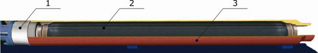

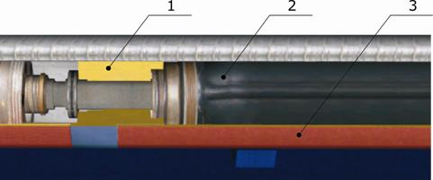


")


