Deciphering power lines - an abbreviation for the phrase "power line". The transmission line is the most important component of energy systems, which serves to transmit electricity from generating devices to distribution, converter and, ultimately, to consumers.
Classification
The transmission of electrical energy is carried out through metal wires, where copper or aluminum acts as a conductor. The wiring method is different:
- By air - by air lines;
- In soil (water) - cable lines;
- gas lines.
The listed types of power lines are the main ones. Experiments are being carried out on wireless power transmission, but at present this method has not found wide distribution in practice, with the exception of low-power devices.

Overhead power lines
Overhead power lines, high voltage power lines, are characterized by high complexity. Their design, operation procedure are regulated by special documentation. Overhead lines are characterized by the fact that electricity is transmitted through wires laid in the open air. To ensure safety and reduce losses, the composition of overhead lines is quite complicated.
Composition VL
What is VL? This is not a high-voltage line, as is sometimes believed. VL is a whole complex of structures and equipment. The main elements that make up any power line:
- Current-carrying wires;
- Bearing supports;
- Insulators.
Other components are also important, but their type, nomenclature and quantity depend on various factors:
- fittings;
- Lightning protection cables;
- Grounding devices;
- Dischargers;
- Sectioning devices;
- Aircraft warning marking;
- Auxiliary equipment (equipment for overlaying communication, remote control);
- Fiber-optic communication line.
The fittings include fasteners for connecting insulators, wires, fastening them to supports.
Note. Surge arresters, grounding and lightning protection devices serve to ensure safety and increase reliability in the event of power surges, including during thunderstorms.
Sectioning devices allow you to turn off part of the power transmission line for the period of routine or emergency work.
High-frequency and fiber-optic communication equipment is designed for dispatching remote monitoring and control of the operation of the line, sectioning devices, substation and distribution devices.
Documents regulating overhead lines
The main documents that regulate any power transmission line are the Building Regulations and Rules (SNiP), as well as the Rules for the installation of electrical installations of the PUE. These documents regulate the design, construction, construction and operation of overhead power lines.
VL classification
A wide variety of designs and types of overhead lines makes it possible to distinguish groups in them, united by common features.
By type of current
Most of the existing transmission lines are designed to work with alternating current, which is due to the ease of converting voltage in magnitude.
Certain types of lines operate with direct current. They are intended for some areas of application (power supply of the contact network, powerful DC consumers), but the total length is small, despite the lower losses in the capacitive and inductive components.
By appointment
- Intersystem (distant) - to combine several energy systems. These include overhead lines of 500 kV and above;
- Trunk - for combining power plants into a network within the same power system and supplying electricity to nodal substations;
- Distribution - for the connection of large enterprises and settlements with nodal substations;
- VL of agricultural consumers;
- Urban and rural distribution network.

According to the mode of operation of neutrals in electrical installations
- Networks with dead-earthed neutral;
- Networks with isolated neutral;
- With resonantly grounded neutral;
- With effectively grounded neutral.
According to the mode of operation depending on the mechanical condition
The main mode of operation of the overhead line is normal, when all wires and cables are in good condition. There may be cases when some of the wires are missing, but the power line is in operation:
- With a complete or partial break - emergency mode;
- During the installation of wires, supports - installation mode.
The main elements of overhead lines
- Route - the location of the axis of the power line relative to the surface of the earth;
- Support foundation - a structure in the ground, on which the support rests, transferring the load from external influences to it;
- Span length - the distance between the centers of adjacent supports;
- Sag - the distance between the lower point of the wire and the conditional straight line between the suspension points of the wires;
- Wire gauge - the distance from the bottom of the wire to the ground.

Cable power lines
What is a cable power line? This type of power lines differs from overhead lines in that the wires of different phases are isolated and combined into a single cable.
According to the conditions of passage
According to the conditions for passing the CL are divided into:
- Underground;
- Underwater;
- By buildings.
cable structures
In addition to the fact that the cable can be in water or land, part of it must pass through cable structures, which include:
- cable channels;
- cable camera;
- cable shaft;
- Double floor;
- cable gallery.

This list is incomplete, the main difference between cable structures and others is that they are intended exclusively for cable installation along with fastening devices, power couplings and branches.
By type of insulation
The most widely used cable lines with solid insulation:
- PVC;
- Oil-paper;
- Rubber-paper;
- Polyethylene (cross-linked polyethylene);
- Ethylene-propylene.
Less common are liquid and gas insulation.
Losses in power lines
Losses in transmission lines have a different nature and are divided into:
- Heating loss:
- Corona Losses:
- Losses due to radio emission;
- Reactive power transmission losses.

Power transmission line supports and other elements
The main element for fastening the wires of a power line is a support. Power transmission towers are divided into two types:
- Anchor (terminal), on which the devices for fastening and tensioning the wire are located;
- Intermediate.
Supports can be installed directly into the ground or on the foundation. According to the material of manufacture:
- Wooden;
- steel;
- Reinforced concrete.
Insulators and fittings
Insulators are designed for fastening and insulating wires of power transmission lines. Suspension insulators have gained the greatest advantage, which allow to make any length from individual elements, depending on the requirements. As a rule, the higher the voltage in kV, the greater the length of the string of insulators.
Made from:
- Porcelain;
- glass;
- polymer materials.

Fittings are used to connect chains of insulators, attaching them to supports and wires. In cable lines, fittings also include couplings.
Protective devices
Lightning conductors, arresters and grounding devices are used as protection. Grounding of metal poles is carried out by mechanically fastening the supporting structure to the ground loop. The grounding of reinforced concrete supports is especially important, since in case of current leakage, it begins to flow through the concrete reinforcement, causing a destructive effect. The damage caused to the support will not be visually visible.

Important! For the best protection, the security wire is placed above all others.
Specifications
The technical characteristics of power transmission lines depend not only on the transmitted voltage and power. The following factors must be taken into account:
- City or non-residential area;
- Dominant weather conditions (temperature range, wind speed);
- Soil condition (solid, movable).
What is a power line? Any power line is a powerful source of electromagnetic field. High-voltage lines located near housing adversely affect health. Determining the minimum harm to health and the environment plays an important role in the design of power lines.
Technical calculations are made in order to determine which type of line should be used to achieve the greatest efficiency.
Video
The movement of electricity is carried out using power lines. Such installations should be hopeful, as well as safe for people and the environment. This article talks about what an overhead power line is, and also presents some simple diagrams.
The abbreviation stands for power lines. This installation is necessary for the transmission of electrical energy through cables located in open areas (air) and installed with insulators and fittings to racks or supports. The line inputs or line outputs of the switchgear are taken as the point of beginning and end of power lines, and for branching - a special support and a line input.
What does a power station look like?
Supports can be divided into:
- intermediate ones that are located on straight sections of the installation route, they are used only to hold cables;
- anchors are mainly mounted on the straight boundaries of overhead lines;
- end posts are a subspecies of anchor posts, they are placed at the beginning and end of the overhead line. Under standard operating conditions of the installation, they take the load from the cables;
- special racks are used to change the position of cables on power lines;
- decorated racks, in addition to support, they play the role of aesthetic beauty.
Power lines can be divided into overhead and underground. The latter are increasingly gaining popularity due to ease of installation, high reliability and reduced voltage losses.
Note! These lines differ in the laying method, design feature. Each has its pros and cons.
When working with power lines, it is necessary to follow all safety rules, because during installation you can not only get injured, but also die.

Types of supports used
Technical characteristics of power lines
The main parameters of the power line:
- l - gaps between racks or supports of power lines;
- dd - space between adjacent cable lines;
- λλ - can be deciphered as the length of the power line garland;
- HH - rack height;
- hh is the shortest distance allowed from the low cable mark to the ground.
Not everyone can decipher all the characteristics of the installations. Therefore, you can turn to a professional for help.
Below is a table of transmission lines updated in 2010. A more complete description can be found on the electrical forums.
| Rated voltage, kV | ||||||
| 40 | 115 | 220 | 380 | 500 | 700 | |
| Gap l, m | 160-210 | 170-240 | 240-360 | 300-440 | 330-440 | 350-550 |
| Space d, m | 3,0 | 4,5 | 7,5 | 9,0 | 11,0 | 18,5 |
| Garland length X, m | 0,8-1,0 | 1,4-1,7 | 2,3-2,8 | 3,0-3,4 | 4,6-5,0 | 6,8-7,8 |
| Rack height H, m | 11-22 | 14-32 | 23-42 | 26-44 | 28-33 | 39-42 |
| Line parameter h, m | 6-7 | 7-8 | 7-8 | 8-11 | 8-14 | 12-24 |
| Number of cables per phase* | 1 | 1 | 2 | 2 | 3 | 4-6 |
| Volume of sections wires, mm2 | 60-185 | 70-240 | 250-400 | 250-400 | 300-500 | 250-700 |
To reduce the number of emergency shutdowns that occur during bad weather conditions, power plant lines are equipped with lightning protection ropes that are installed on racks above the cables and are used to suppress direct lightning strikes into power lines. They are similar to metal galvanized multi-wire cables or special small section reinforced aluminum cables.
Such lightning protection devices are produced and used with optical fiber cores built into their tubular rod, which provide multi-channel communication. In areas with constantly recurring and severe frosts, ice is deposited on wires and accidents are formed due to breaking through overhead lines when sagging ropes and cables approach.
The operating temperature of power lines is from 150 to 200 degrees. The wires are not insulated inside. They must have a high degree of conductivity, as well as resistance to mechanical damage.
The following describes which power lines are used to transmit electricity.
Kinds
Power lines are used to move and distribute electricity. Line types can be divided:
- by type of cable location - air (located in the open air) and closed (in cable channels);
- by function - ultra-long, for highways, distribution.
Overhead power lines can also be divided into subspecies, which depend on conductors, type of current, power, raw materials used. These classifications are detailed below.
Alternating current
According to the type of current, power lines can be divided into two groups. The first of these is DC power lines. Such installations help to minimize losses when moving energy, therefore they are used to transmit current over long distances. This type of power transmission line is quite popular in European countries, but in Russia such power lines can be counted on the fingers. Many railroads run on alternating current.

Power transmission scheme
Direct current
The second group is DC power lines, in which the energy is always the same regardless of direction and resistance. Almost all installations in Russia are powered by direct current. They are easier to produce and operate, but the losses during the movement of current very often reach 10 kW / km for six months on a power line with a voltage of 450 kV.
Power line classification
Such installations can be classified by purpose, voltage, mode of operation, and so on. Each item is described in detail below.
By type of current
In recent years, electricity transmission has been carried out mainly on alternating current. This method is popular because most electricity sources produce AC voltage (with the exception of individual sources, such as solar panels), and AC installations are the main consumer.

Wiring diagram for overhead lines
Very often DC power transmission is more favorable. To reduce losses in power lines, during the transmission of electrical energy on any type of current, with the help of transformers (TT) raise the voltage.
Also, when performing a transfer from the installation to the consumer at direct current, it is necessary to convert electrical energy from alternating current to direct current, for this there are special rectifiers.
By destination
According to the purpose of the power lines can be divided into several types. According to the distance, the lines are divided into:
- ultra-long. On such power lines, the voltage will be over 500 kilovolts. They are used to move energy over long distances. Basically, they are necessary in order to combine different power systems or their elements;
- trunk. Such lines come with a voltage of 220 or 380 kV. They combine with each other large energy centers or different installations;
- distribution. This type includes systems with a voltage of 35, 110 and 150 kV. They are used to unite districts and small feeding centers;
- supplying electricity to people. Voltage - no higher than 20 kV, the most popular types are 6 and 10 kV. These power lines bring energy to distribution points, and then to people in the house.
By voltage
According to the base voltage, such power lines are mainly divided into two main groups. With low voltage up to 1 kV. GOSTs indicate four main voltages, 40, 220, 380 and 660 V.
With voltage above 1 kV. GOST describes 12 parameters here, average indicators - from 3 to 35 kV, high - from 100 to 220 kV, the highest - 330, 500 and 700 kV and ultra-high - more than 1 MV. It is also called high voltage.

According to the system of functioning of neutrals in electrical installations
Such installations can be divided into four networks:
- three-phase, in which there is no grounding. Basically, this scheme is used in networks with voltages up to 35 kV, where small currents move;
- three-phase, in which there is grounding using inductance. This installation is also called the resonant-grounded type. In such overhead lines, a voltage of 3-35 kV is used, where large currents move;
- three-phase, in which there is a full ground. This mode of operation of the neutral is used in overhead lines with medium and high voltages. Here you need to use current transformers;
- grounded neutral. Overhead lines with a voltage of less than 1.0 kV or more than 220 kV operate here.

Mounting process
According to the mode of operation depending on the mechanical condition
There is also such a separation of power lines, which provides for the external state of all parts of the installation. These are power lines in good condition, where cables, racks and other items are almost new. The main emphasis is on the quality of cables and ropes, they should not be mechanically damaged.
There is also an emergency situation, where the quality of cables and ropes is quite low. Such installations require immediate repair.
- power lines in good working order - all components are new and not damaged;
- emergency lines - with obvious visible damage to the wires;
- installation lines - during the installation of racks, cables and ropes.
It is only necessary for an experienced electrician to determine the condition of power lines.
If the installation is emergency, then this can lead to a number of consequences. For example, energy will not be supplied constantly, a short circuit is possible, bare wires can cause a fire when they come into contact. If the power line was not installed on time and irreparable consequences occurred, then this can lead to huge fines.

Underground cable power lines
Purpose of overhead lines
Such overhead lines are called installations that are used to move and distribute electrical energy through cables located in the open air and held with the help of special racks. Overhead lines are installed and used in a variety of weather conditions and geographic areas, prone to atmospheric influences (precipitation, temperature changes, winds).
Therefore, overhead lines must be installed taking into account weather factors, atmospheric pollution, laying requirements (for a city, field, village), and so on. The installation must comply with a number of rules and regulations:
- cost-effective cost;
- high electrical conductivity, strength of the ropes and racks used;
- resistance to mechanical damage, corrosion;
- be safe for nature and man, do not occupy a lot of free territory.

What do insulators look like?
What is the voltage of the power line
According to certain characteristics, you can find out the voltage of power lines in appearance. The first thing you should pay attention to is the insulator. The more of them are on the installation, the more powerful it will be.
The most popular insulators for overhead lines 0.4kV. They are usually made of durable glass. By their number can be determined in power.
VL-6 and VL-10 are similar in shape, but much larger. In addition to pin fixing, such insulators are sometimes used in the same way as garlands in one / two samples.
Note! On a 35 kV overhead line, hanging insulators are most often installed, although sometimes you can see a pin type. The garland consists of three to five types.
The number of rollers in a garland can be as follows:
- VL-110kV - 6 rollers;
- VL-220kV - 10 rollers;
- VL-330kV - 12 rollers;
- VL-500kV - 22 rollers;
- VL-750kV - from 20 and above.

How to find out the power of power lines
You can also find out the voltage by the number of cables:
- VL-0.4 kV number of wires from 2 to 4 and more;
- VL-6, 10 kV - only three cables per unit;
- VL-35 kV, 110 kV - each insulator has its own wire;
- VL-220 kV - for each insulator one large wire;
- VL-330 kV - in phases of two cables;
- VL-750 kV - from 3 to 5 wires.
In conclusion, it should be noted that in the modern world it is impossible to do without power lines. They supply the entire country with electricity. Currently, air and cable power lines are used everywhere.
Encyclopedic YouTube
1 / 5
✪ How power lines work. Transmission of energy over long distances. Animated training video. / Lesson 3
✪ Lesson 261 The condition for matching the current source with the load
✪ Installation methods for overhead power lines (lecture)
✪ ✅ How to charge a phone under a high-voltage power line with induced currents
✪ Dance of the wires of the overhead power line 110 kV
Subtitles
Overhead power lines
Overhead power line(VL) - a device designed for the transmission or distribution of electrical energy through wires located in the open air and attached with the help of traverses (brackets), insulators and fittings to supports or other structures (bridges, overpasses).
Composition VL
- Traverses
- Partitioning devices
- Fiber-optic communication lines (in the form of separate self-supporting cables, or built into a lightning protection cable, power wire)
- Auxiliary equipment for the needs of operation (equipment for high-frequency communication, capacitive power take-off, etc.)
- Elements for marking high-voltage wires and power transmission line poles to ensure the safety of aircraft flights. Supports are marked with a combination of paints of certain colors, wires - with aviation balloons for marking in the daytime. To indicate in the daytime and at night, the lights of the light fence are used.
Documents regulating overhead lines
VL classification
By type of current
Basically, overhead lines are used to transmit alternating current, and only in some cases (for example, for connecting power systems, powering a contact network, and others), direct current lines are used. DC lines have lower capacitive and inductive losses. In the USSR, several DC power lines were built:
- High-voltage direct current line Moscow-Kashira - Project "Elba",
- High voltage DC line Volgograd-Donbass,
- High-voltage direct current line Ekibastuz-Center, etc.
Such lines were not widely used.
By appointment
- Extra-long overhead lines with a voltage of 500 kV and above (designed to connect individual power systems).
- Main overhead lines with a voltage of 220 and 330 kV (designed to transmit energy from powerful power plants, as well as to connect power systems and combine power plants within power systems - for example, connect power plants with distribution points).
- Distribution overhead lines with a voltage of 35, 110 and 150 kV (intended for power supply of enterprises and settlements in large areas - connect distribution points with consumers)
- VL 20 kV and below, supplying electricity to consumers.
By voltage
- VL up to 1000 V (VL of the lowest voltage class)
- VL above 1000 V
- VL 1-35 kV (VL medium voltage class)
- VL 35-330 kV (VL of high voltage class)
- VL 500-750 kV (VL of extra-high voltage class)
- Overhead lines above 750 kV (overhead lines of ultra-high voltage class)
These groups differ significantly, mainly in terms of requirements in terms of design conditions and structures.
In LPG networks of general purpose AC 50 Hz, according to GOST 721-77, the following nominal phase-to-phase voltages must be used: 380; (6) , 10, 20, 35, 110, 220, 330, 500, 750 and 1150 kV. There may also be networks built according to outdated standards with nominal phase-to-phase voltages: 220, 3 and 150 kV.
The highest voltage transmission line in the world is the Ekibastuz-Kokchetav line, with a nominal voltage of 1150 kV. However, at present the line is operated under half the voltage - 500 kV.
The rated voltage for DC lines is not regulated, the most commonly used voltages are: 150, 400 (Vyborgskaya PS - Finland) and 800 kV.
Other voltage classes can be used in special networks, mainly for railway traction networks (27.5 kV, 50 Hz AC and 3.3 kV DC), underground (825 V DC), trams and trolleybuses (600 in direct current).
According to the mode of operation of neutrals in electrical installations
- Three-phase networks with ungrounded (isolated) neutrals (the neutral is not connected to the grounding device or is connected to it through devices with high resistance). In the CIS, such a neutral mode is used in networks with a voltage of 3-35 kV with low currents of single-phase earth faults.
- Three-phase networks with resonantly grounded (compensated) neutrals (the neutral bus is connected to earth via an inductance). In the CIS, it is used in networks with a voltage of 3-35 kV with high currents of single-phase earth faults.
- Three-phase networks with effectively grounded neutrals (high and extra-high voltage networks, the neutrals of which are connected to the ground directly or through a small active resistance). In Russia, these are networks with a voltage of 110, 150 and partially 220 kV, in which transformers are used (autotransformers require obligatory deaf neutral grounding).
- Networks with deaf-earthed neutral (the neutral of the transformer or generator is connected to the grounding device directly or through a small resistance). These include networks with a voltage of less than 1 kV, as well as networks with a voltage of 220 kV and above.
According to the mode of operation depending on the mechanical condition
- Overhead line of normal operation (wires and cables are not broken).
- Overhead lines of emergency operation (with a complete or partial breakage of wires and cables).
- VL of the installation mode of operation (during the installation of supports, wires and cables).
The main elements of overhead lines
- track- the position of the axis of the overhead line on the earth's surface.
- Pickets(PC) - the segments into which the route is divided, the length of the PC depends on the nominal voltage of the overhead line and the type of terrain.
- Zero picket sign marks the beginning of the route.
- center sign on the route of the overhead line under construction, it indicates the center of the support location.
- Production picketing- installation of picket and center signs on the route in accordance with the statement of the placement of supports.
- support foundation- a structure embedded in the ground or resting on it and transferring the load to it from the support, insulators, wires (cables) and from external influences (ice, wind).
- foundation foundation- soil of the lower part of the pit, which takes the load.
- span(span length) - the distance between the centers of the two supports on which the wires are suspended. Distinguish intermediate span (between two adjacent intermediate supports) and anchor span (between anchor supports). transition span- a span crossing any structure or natural obstacle (river, ravine).
- Line rotation angle- angle α between the directions of the overhead line route in adjacent spans (before and after the turn).
- Sag- the vertical distance between the lowest point of the wire in the span and the straight line connecting the points of its attachment to the supports.
- Wire size- vertical distance from the wire in the span to the engineering structures intersected by the route, the surface of the earth or water.
- Plume (the loop) - a piece of wire connecting the stretched wires of adjacent anchor spans on the anchor support.
Installation of overhead power lines
The installation of power transmission lines is carried out by the "Mounting" "pull-up" method. This is especially true in the case of complex terrain. When selecting equipment for the installation of power transmission lines, it is necessary to take into account the number of wires in the phase, their diameter and the maximum distance between the power transmission line supports.
Cable power lines
Cable power line(KL) - a line for the transmission of electricity or its individual impulses, consisting of one or more parallel cables with connecting, locking and end couplings (terminals) and fasteners, and for oil-filled lines, in addition, with feeders and an oil pressure alarm system .
Classification
Cable lines are classified similarly to overhead lines. In addition, cable lines share:
- according to the conditions of passage:
- underground;
- by buildings;
- underwater.
- type of insulation:
- liquid (impregnated with cable oil oil);
- solid:
- paper-oil;
- polyvinyl chloride (PVC);
- rubber-paper (RIP);
- ethylene propylene rubber (EPR).
Gaseous insulation and some types of liquid and solid insulation are not indicated here due to their relatively rare use at the time of writing [ when?] .
cable structures
Cable structures include:
- cable tunnel- a closed structure (corridor) with supporting structures located in it for placing cables and cable boxes on them, with free passage along the entire length, which allows cable laying, repair and inspection of cable lines.
- cable channel- an impassable structure, closed and partially or completely buried in the ground, floor, ceiling, etc., and intended for placing cables in it, laying, inspecting and repairing which can only be done with the ceiling removed.
- cable shaft- a vertical cable structure (usually of a rectangular section), whose height is several times greater than the side of the section, equipped with brackets or a ladder for people to move along it (passage shafts) or a wall that is fully or partially removable (impassable shafts).
- cable floor- a part of the building bounded by the floor and the floor or cover, with a distance between the floor and the protruding parts of the floor or cover of at least 1.8 m.
- double floor- a cavity bounded by the walls of the room, the interfloor overlap and the floor of the room with removable plates (on the whole or part of the area).
- cable block- cable structure with pipes (channels) for laying cables in them with wells related to it.
- cable camera- an underground cable structure closed with a deaf removable concrete slab, designed for laying cable boxes or for pulling cables into blocks. A chamber having a hatch to enter it is called cable well.
- cable rack- above-ground or ground open horizontal or inclined extended cable structure. Cable overpass can be passable or non-passage.
- cable gallery- above ground or ground closed (in whole or in part, for example, without side walls) horizontal or inclined extended cable structure.
Fire safety
The temperature inside the cable channels (tunnels) in summer should be no more than 10 °C higher than the outside air temperature.
In case of fires in cable rooms, in the initial period, combustion develops slowly and only after some time does the combustion spread rate increase significantly. Practice shows that during real fires in cable tunnels, temperatures up to 600 ° C and above are observed. This is explained by the fact that in real conditions, cables burn, which are under current load for a long time and the insulation of which warms up from the inside to a temperature of 80 ° C and above. Simultaneous ignition of cables in several places and over a considerable length can occur. This is due to the fact that the cable is under load and its insulation is heated to a temperature close to the self-ignition temperature.
The cable consists of many structural elements, for the manufacture of which a wide range of combustible materials are used, including materials with a low ignition temperature, materials prone to smoldering. Also, the design of the cable and cable structures includes metal elements. In the event of a fire or current overload, these elements are heated to a temperature of about 500-600 ˚C, which exceeds the ignition temperature (250-350 ˚C) of many polymeric materials included in the cable structure, and therefore they can be re-ignited from heated metal elements after stopping the supply of fire extinguishing agent. In this regard, it is necessary to choose the normative indicators for the supply of fire extinguishing agents in order to ensure the elimination of fiery combustion, as well as to exclude the possibility of re-ignition.
For a long time, foam extinguishing installations were used in cable rooms. However, operating experience revealed a number of shortcomings:
- limited shelf life of the foaming agent and the inadmissibility of storing their aqueous solutions;
- instability in work;
- complexity of setup;
- the need for special care for the foam concentrate dosing device;
- rapid destruction of the foam at high (about 800 ° C) ambient temperature during a fire.
Studies have shown that sprayed water has a greater fire extinguishing ability compared to air-mechanical foam, as it wets and cools burning cables and building structures well.
The linear speed of flame propagation for cable structures (cable burning) is 1.1 m/min.
High temperature superconductors
HTS wire
Losses in power lines
The loss of electricity in the wires depends on the strength of the current, therefore, when transmitting it over long distances, the voltage is increased many times (by the same amount reducing the current strength) with the help of a transformer, which, when transmitting the same power, can significantly reduce losses. However, as the voltage increases, various discharge phenomena begin to occur.
In ultra-high voltage overhead lines, there are active power losses to the corona (corona discharge). A corona discharge occurs when the electric field strength E (\displaystyle E) at the surface of the wire will exceed the threshold value E k (\displaystyle E_(k)), which can be calculated using Pick's empirical formula:
E k = 30 , 3 β (1 + 0.298 r β) (\displaystyle E_(k)=30(,)3\beta \left((1+(\frac (0(,)298)(\sqrt (r \beta))))\right)) kV/cm,
where r (\displaystyle r)- radius of the wire in meters, β (\displaystyle \beta )- the ratio of air density to normal.
The electric field strength is directly proportional to the voltage on the wire and inversely proportional to its radius, so corona losses can be combated by increasing the radius of the wires, and also (to a lesser extent) by using phase splitting, that is, using several wires in each phase held by special spacers at a distance of 40-50 cm. The corona loss is approximately proportional to the product U (U − U cr) (\displaystyle U(U-U_(\text(cr)))).
Losses in AC power lines
An important value that affects the efficiency of AC transmission lines is the value that characterizes the ratio between active and reactive power in the line - cos φ. Active power - part of the total power that passed through the wires and transferred to the load; Reactive power is the power that is generated by the line, its charging power (capacitance between the line and ground), as well as the generator itself, and is consumed by a reactive load (inductive load). Active power losses in the line also depend on the transmitted reactive power. The greater the flow of reactive power, the greater the loss of active.
With a length of AC power lines of more than several thousand kilometers, another type of loss is observed - radio emission. Since such a length is already comparable with the length of an electromagnetic wave with a frequency of 50 Hz ( λ = c / ν = (\displaystyle \lambda =c/\nu =) 6000 km, quarter wave vibrator length λ / 4 = (\displaystyle \lambda /4=) 1500 km), the wire works as a radiating antenna.
Natural power and transmission capacity of power lines
natural power
Power lines have inductance and capacitance. Capacitive power is proportional to the square of the voltage, and does not depend on the power transmitted over the line. The inductive power of the line is proportional to the square of the current, and hence the power of the line. At a certain load, the inductive and capacitive powers of the line become equal, and they cancel each other out. The line becomes "ideal", consuming as much reactive power as it produces. This power is called natural power. It is determined only by the linear inductance and capacitance, and does not depend on the length of the line. By the value of natural power, one can roughly judge the transmission capacity of the power line. When transmitting such power on the line, there is minimal power loss, the mode of its operation is optimal. When splitting the phases, by reducing the inductive resistance and increasing the capacitance of the line, the natural power increases. With an increase in the distance between the wires, the natural power decreases, and vice versa, to increase the natural power, it is necessary to reduce the distance between the wires. Cable lines with high capacitive conductivity and low inductance have the highest natural power.
Bandwidth
Power transmission capacity is understood as the maximum active power of the three phases of power transmission, which can be transmitted in a long-term steady state, taking into account operational and technical restrictions. The highest transmitted active power of power transmission is limited by the conditions of static stability of generators of power plants, the transmitting and receiving parts of the electric power system, and the allowable power for heating line wires with allowable current. From the practice of operating electric power systems, it follows that the transmission capacity of power transmission lines of 500 kV and above is usually determined by the static stability factor, for power transmission lines of 220-330 kV, restrictions can occur both in terms of stability and in permissible heating, 110 kV and below - only in heating.
Characteristics of the throughput capacity of overhead power lines
At the very beginning of the 20th century, the outstanding inventor of Serbian origin, Nikola Tesla, worked on the wireless option for transmitting electricity, but even a century later, such developments did not receive large-scale industrial application. The main way to deliver energy to the consumer is still cable and overhead power lines.
Power lines: purpose and types
The power line is perhaps the most important component of electrical networks, which is part of the system of power equipment and devices, the main purpose of which is the transfer of electrical energy from installations that produce it (power plants), convert and distribute it (electric substations) to consumers. In general cases, this is the name of all electrical lines that are outside the listed electrical structures.
Historical reference: the first power transmission line (direct current, voltage 2 kV) was built in Germany according to the project of the French scientist F. Despres in 1882. It had a length of about 57 km and connected the cities of Munich and Miesbach.
According to the method of installation and arrangement, cable and overhead power lines are divided. In recent years, especially for the energy supply of megacities, gas-insulated lines have been erected. They are used to transmit high power in very dense buildings to save the area occupied by power lines and ensure environmental standards and requirements.
Cable lines are used where the arrangement of air lines is difficult or impossible due to technical or aesthetic parameters. Due to the relative cheapness, better maintainability (on average, the time to eliminate an accident or malfunction is 12 times less) and high throughput, overhead power lines are most in demand.
Definition. General classification
Electric overhead line (OHTL) - a set of devices located in the open air and intended for the transmission of electricity. The structure of overhead lines includes wires, traverses with insulators, supports. As the latter, in some cases, structural elements of bridges, overpasses, buildings and other structures can act. During the construction and operation of overhead power lines and networks, various auxiliary fittings (lightning protection, grounding devices), additional and related equipment (high-frequency and fiber-optic communication, intermediate power take-off) and component marking elements are also used.
According to the type of energy transmitted, overhead lines are divided into AC and DC networks. The latter, due to certain technical difficulties and inefficiency, have not received wide distribution and are used only for power supply to specialized consumers: DC drives, electrolysis shops, urban contact networks (electrified transport).
According to the rated voltage, overhead power lines are usually divided into two large classes:
- Low-voltage, voltage up to 1 kV. State standards define four nominal values: 40, 220, 380 and 660 V.
- High voltage, over 1 kV. Twelve nominal values are defined here: medium voltage - from 3 to 35 kV, high - from 110 to 220 kV, ultra-high - 330, 500 and 700 kV and ultra-high - over 1 MV.
Note: all the given figures correspond to the interphase (linear) voltage of a three-phase network (six- and twelve-phase systems do not have a serious industrial distribution).
From GOELRO to UES
The following classification describes the infrastructure and functionality of overhead power lines.
According to the coverage of the territory, the network is divided into:
- for ultra-long distance (voltage over 500 kV), intended for connection of regional energy systems;
- trunk lines (220, 330 kV) serving for their formation (connection of power plants with distribution facilities);
- distribution (35 - 150 kV), the main purpose of which is the supply of electricity to large consumers (industrial facilities, the agricultural complex and large settlements);
- supply or supply (below 20 kV), providing power supply to other consumers (urban, industrial and agricultural).
Overhead power lines are important in the formation of the Unified Energy System of the country, the foundation of which was laid during the implementation of the GOELRO (State Electrification of Russia) plan of the young Soviet Republic about a century ago to ensure a high level of reliability of energy supply, its fault tolerance.
According to the topological structure and configuration, overhead transmission lines can be open (radial), closed, with backup (containing two or more sources) power.
According to the number of parallel circuits passing along one route, the lines are divided into single-, double- and multi-circuit (a circuit is understood as a complete set of wires of a three-phase network). If the circuits have different nominal voltage values, then such an overhead transmission line is called combined. Chains can be attached both on one support and on different ones. Naturally, in the first case, the mass, dimensions and complexity of the support increase, but the line's security zone is reduced, which in densely populated areas sometimes plays a decisive role in the preparation of the project.
Additionally, separation of overhead lines and networks is used, based on the design of neutrals (isolated, solidly grounded, etc.) and the mode of operation (regular, emergency, installation).

Secured territory
To ensure the safety, normal functioning, ease of maintenance and repair of overhead power lines, as well as to prevent injuries and deaths of people, zones with a special mode of use are introduced along the routes. Thus, the security zone of overhead power lines is a land plot and the air space above it, enclosed between vertical planes, standing at a certain distance from the extreme wires. In security zones, the work of lifting equipment, the construction of buildings and structures is prohibited. The minimum distance from the overhead power line is determined by the rated voltage.
When crossing non-navigable reservoirs, the protective zone of overhead power lines corresponds to similar distances, and for navigable ones its size increases to 100 meters. In addition, the guidelines determine the smallest distances of wires from the surface of the earth, industrial and residential buildings, trees. It is forbidden to lay high-voltage lines over the roofs of buildings (except for industrial ones, in specially specified cases), over the territories of children's institutions, stadiums, cultural and entertainment and shopping areas.

Supports - structures made of wood, reinforced concrete, metal or composite materials to ensure the required distance of wires and lightning protection cables from the earth's surface. The most budget option - wooden racks, which were used very widely in the last century in the construction of high-voltage lines - are gradually being decommissioned, and new ones are almost never installed. The main elements of overhead transmission line towers include:
- foundation foundations,
- racks,
- struts,
- stretch marks.
Structures are divided into anchor and intermediate. The first ones are installed at the beginning and end of the line, when the direction of the route changes. A special class of anchor supports are transitional, used at the intersections of high-voltage power lines with water arteries, overpasses and similar objects. These are the most massive and highly loaded structures. In difficult cases, their height can reach 300 meters!
The strength and dimensions of the construction of intermediate supports, used only for straight sections of the tracks, are not so impressive. Depending on the purpose, they are divided into transposition (serving to change the location of the phase wires), cross, branch, low and high. Since 1976, all supports have been strictly unified, but today there is a process of moving away from the mass use of standard products. They try to adapt each track as much as possible to the conditions of the relief, landscape and climate.

The main requirement for high-voltage transmission lines is high mechanical strength. They are divided into two classes - non-isolated and isolated. They can be made in the form of stranded and single-wire conductors. The latter, consisting of one copper or steel core, are used only for the construction of low voltage lines.
Stranded wires for overhead power lines can be made of steel, alloys based on aluminum or pure metal, copper (the latter, due to their high cost, are practically not used on long routes). The most common conductors are made of aluminum (the letter "A" is present in the designation) or steel-aluminum alloys (grade AS or ASU (reinforced)). Structurally, they are twisted steel wires, on top of which aluminum conductors are wound. Steel, for protection against corrosion, galvanized.
The choice of section is made in accordance with the transmitted power of the allowable voltage drop, mechanical characteristics. The standard sections of wires produced in Russia are 6, 10, 16, 25, 35, 50, 70, 95, 120 and 240. An idea of the minimum sections of wires used for the construction of overhead lines can be obtained from the table below.
Branches are often performed with insulated wires (brands APR, AVT). Products have a weather-resistant insulating coating and a steel carrier cable. Wire connections in spans are mounted in areas not subject to mechanical stress. They are spliced by crimping (using appropriate devices and materials) or by welding (with thermite checkers or a special apparatus).
In recent years, self-supporting insulated wires have been increasingly used in the construction of overhead lines. For low voltage overhead power lines, the industry produces SIP-1, -2 and -4 grades, and for 10-35 kV lines - SIP-3.

On routes with voltages over 330 kV, to prevent corona discharges, the use of a split phase is practiced - one wire of large cross section is replaced by several smaller ones fastened together. With an increase in the rated voltage, their number increases from 2 to 8.
Linear reinforcement
VTL fittings include traverses, insulators, clamps and suspensions, strips and spacers, fasteners (brackets, clamps, hardware).
The main function of traverses is to fasten wires in such a way as to provide the necessary distance between opposite phases. Products are special metal structures made of angles, strips, pins, etc. with a painted or galvanized surface. There are about two dozen standard sizes and types of traverses, weighing from 10 to 50 kg (designated as TM-1 ... TM22).
Insulators are used for reliable and safe fastening of wires. They are divided into groups, depending on the material of manufacture (porcelain, tempered glass, polymers), functional purpose (support, through passage, introductory) and methods of attachment to traverses (pin, rod and suspension). Insulators are made for a certain voltage, which must be indicated in the alphanumeric marking. The main requirements for this type of fittings when installing overhead power lines are mechanical and electrical strength, heat resistance.
To reduce line vibration and prevent wire breaks, special damping devices or damping loops are used.

Technical parameters and protection
When designing and installing overhead power lines, the following important characteristics are taken into account:
- The length of the intermediate span (the distance between the axes of adjacent racks).
- The distance of the phase conductors from each other and the lowest one from the surface of the earth (line size).
- The length of the string of insulators according to the rated voltage.
- full height of supports.
You can get an idea about the main parameters of overhead power lines of 10 kV and above from the table.
To prevent damage to overhead lines and prevent emergency shutdowns during a thunderstorm, a steel or steel-aluminum wire lightning rod with a cross section of 50-70 mm 2, grounded on supports, is launched above the phase wires. Often it is made hollow, and this space is used to organize high-frequency communication channels.
Valve arresters provide protection against surges arising from lightning strikes. In the event of an induced lightning impulse on the wires, a breakdown of the spark gap occurs, as a result of which the discharge flows to the support, which has the ground potential, without damaging the insulation. Support resistance is reduced using special grounding devices.
Preparation and installation
The technological process of the construction of the overhead transmission line consists of preparatory, construction and installation and commissioning works. The former include the purchase of equipment and materials, reinforced concrete and metal structures, the study of the project, the preparation of the route and picketing, the development of a PEP (plan for the production of electrical work).
Construction work includes digging pits, installing and assembling supports, distributing rebar and grounding kits along the route. The direct installation of overhead power lines begins with the rolling of wires and cables, making connections. This is followed by lifting them to the supports, stretching, sighting the sag arrows (the greatest distance between the wire and the straight line connecting the points of its attachment to the supports). Finally, wires and cables are tied on insulators.
In addition to general safety measures, work on overhead power lines implies compliance with the following rules:
- Cessation of all work when a thunderstorm front approaches.
- Ensuring the protection of personnel from the effects of electrical potentials induced in the wires (shorting and grounding).
- Prohibition of work at night (except for the installation of intersections with overpasses, railways), ice, fog, with a wind speed of more than 15 m / s.
Before commissioning, check the sag and the dimensions of the line, measure the voltage drop in the connectors, the resistance of the grounding devices.

Maintenance and repair
According to the work regulations, all overhead lines over 1 kV every six months are subject to inspection by maintenance personnel, engineering and technical workers - once a year, for the following faults:
- throwing foreign objects on the wires;
- breaks or burnout of individual phase wires, violation of the adjustment of the sag arrows (should not exceed the design ones by more than 5%);
- damage or overlap of insulators, garlands, arresters;
- destruction of supports;
- violations in the security zone (storage of foreign objects, finding oversized equipment, narrowing the width of the clearing due to the growth of trees and shrubs).
Extraordinary inspections of the route are carried out during the formation of ice, during the period of flooding of rivers, natural and man-made fires, as well as after automatic shutdown. Climbing inspections are carried out as needed (at least once every 6 years).
If a violation of the integrity of a part of the wires of the wire (up to 17% of the total cross section) is detected, the damaged area is restored by applying a repair sleeve or bandage. In case of large damage, the wire is cut and reconnected with a special clamp.
During the current repair of the airway, lopsided supports and struts are straightened, all threaded connections are checked for tightening, the protective paint layer on metal structures, numbering, signs and posters are restored. Measure the resistance of grounding devices.
The overhaul of overhead power lines implies the implementation of all current repairs. In addition, a complete wiring is carried out with the measurement of the contact resistance of the couplings and post-repair testing.
Overhead power line(VL) - a device designed for the transmission or distribution of electrical energy through wires with a protective insulating sheath (VLZ) or bare wires (VL) located in the open air and attached with the help of traverses (brackets), insulators and linear fittings to supports or other engineering structures (bridges, overpasses). The main elements of the VL are:
- wires;
- protective cables;
- a support that supports wires and hummocks at a certain height above ground or water level;
- insulators that isolate the wires from the body of the support;
- linear armature.
Linear portals of distribution devices are taken as the beginning and end of the overhead line. According to the constructive device, overhead lines are divided into single-circuit and multi-valued, as a rule, 2-circuit.
Usually, an overhead line consists of three phases, so the supports of single-circuit overhead lines with a voltage above 1 kV are designed for hanging three phase wires (one circuit) (Fig. 1), six wires are suspended on the supports of double-circuit overhead lines (two parallel circuits). If necessary, one or two lightning protection cables are suspended above the phase wires. From 5 to 12 wires are suspended on the supports of the overhead line of the distribution network with a voltage of up to 1 kV to supply various consumers with one overhead line (outdoor and indoor lighting, electric power, household loads). An overhead line with a voltage of up to 1 kV with a dead-earthed neutral, in addition to the phase ones, is equipped with a neutral wire.

Rice. one. Fragments of 220 kV overhead lines:a - single-chain; b - double-chain
The wires of overhead transmission lines are mainly made of aluminum and its alloys, in some cases of copper and its alloys, they are made of cold-drawn wire with sufficient mechanical strength. However, the most widespread are multi-wire wires made of two metals with good mechanical characteristics and relatively low cost. Wires of this type include steel-aluminum wires with a cross-sectional area ratio of aluminum and steel parts from 4.0 to 8.0. Examples of the location of phase wires and lightning protection cables are shown in fig. 2, and the design parameters of the overhead line of a standard range of voltages are given in table. one.

Rice. 2. : a - triangular; b - horizontal; in - hexagonal "barrel"; d - reverse "Christmas tree"
Table 1. Structural parameters of overhead lines
| Rated VL voltage, kV | The distance between phase wires, m | Length span, m | Height | Dimension |
| Less than 1 | 0,5 | 40 – 50 | 8 – 9 | 6 – 7 |
| 6 – 10 | 1,0 | 50 – 80 | 10 | 6 – 7 |
| 35 | 3 | 150 – 200 | 12 | 6 – 7 |
| 110 | 4 – 5 | 170 – 250 | 13 – 14 | 6 – 7 |
| 150 | 5,5 | 200 – 280 | 15 – 16 | 7 – 8 |
| 220 | 7 | 250 – 350 | 25 – 30 | 7 – 8 |
| 330 | 9 | 300 – 400 | 25 – 30 | 7,5 – 8 |
| 500 | 10 – 12 | 350 – 450 | 25 – 30 | 8 |
| 750 | 14 – 16 | 450 – 750 | 30 – 41 | 10 – 12 |
| 1150 | 12 – 19 | – | 33 – 54 | 14,5 – 17,5 |
For all the above options for the location of phase wires on supports, an asymmetric arrangement of wires in relation to each other is characteristic. Accordingly, this leads to unequal reactance and conductivity of different phases, due to the mutual inductance between the wires of the line and, as a result, to phase voltage unbalance and voltage drop.
In order to make the capacitance and inductance of all three phases of the circuit the same, a transposition of wires is used on the power line, i.e. mutually change their location relative to each other, while each phase wire passes one third of the path (Fig. 3). One such triple movement is called a transposition cycle.
![]()
Rice. 3. Scheme of the full cycle of transposition of sections of an overhead power line: 1, 2, 3 - phase wires
The transposition of the phase wires of an overhead power line with bare wires is used for a voltage of 110 kV and above and with a line length of 100 km or more. One of the options for mounting wires on a transposition support is shown in fig. 4. It should be noted that the transposition of current-carrying cores is sometimes used in cable lines, in addition, modern technologies for designing and constructing overhead lines make it possible to technically implement control of line parameters (controlled self-compensating lines and compact overhead lines of ultra-high voltage).
![]()
Rice. 4.
The wires and protective cables of the overhead line in certain places must be rigidly fixed on the tension insulators of the anchor supports (end supports 1 and 7, installed at the beginning and end of the overhead line, as shown in Fig. 5 and stretched to a predetermined tension. Intermediate supports are installed between the anchor supports , necessary to support wires and cables, with the help of supporting garlands of insulators with supporting clamps, at a given height (supports 2, 3, 6), installed on a straight section of overhead lines; angular (supports 4 and 5), installed at turns of the overhead line route; transitional (supports 2 and 3) installed in the span of the overhead line crossing any natural obstacle or engineering structure, for example, a railway or highway.

Rice. 5.
The distance between the anchor supports is called the anchor span of the overhead power line (Fig. 6). The horizontal distance between the wire attachment points on adjacent supports is called the span length. L . A sketch of the overhead line span is shown in fig. 7. The length of the span is chosen mainly for economic reasons, except for transitional spans, taking into account both the height of the supports and the sagging of wires and cables, as well as the number of supports and insulators along the entire length of the overhead line.
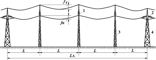
Rice. 6. : 1 - supporting garland of insulators; 2 - tension garland; 3 - intermediate support; 4 - anchor support
The smallest vertical distance from the ground to the wire at its greatest sag is called the line gauge to the ground - h . The line size must be maintained for all rated voltages, taking into account the risk of closing the air gap between the phase conductors and the highest point of the terrain. It is also necessary to take into account the environmental aspects of the impact of high electromagnetic field strengths on living organisms and plants.
The largest deviation of the phase wire f n or ground wire f t from the horizontal under the action of a uniformly distributed load from its own mass, the mass of ice and wind pressure is called the sag. To prevent wires from lashing, the cable sag boom is less than the wire sag boom by 0.5 - 1.5 m.
Structural elements of overhead lines, such as phase wires, cables, garlands of insulators, have a significant mass, so the forces acting on one support reach hundreds of thousands of newtons (N). The tensile forces on the wire from the weight of the wire, the weight of the tension garlands of insulators and ice formations are directed downwards along the normal, and the forces due to the wind pressure are directed along the normal away from the wind flow vector, as shown in Fig. 7.

Rice. 7.
In order to reduce the inductive resistance and increase the throughput of long-distance overhead lines, various versions of compact transmission lines are used, a characteristic feature of which is the reduced distance between the phase wires. Compact power transmission lines have a narrower spatial corridor, a lower level of electric field strength at ground level and allow technical implementation of line parameter control (controlled self-compensating lines and lines with an unconventional split-phase configuration).
2. Cable power line
Cable power line (KL) consists of one or more cables and cable fittings for connecting cables and for connecting cables to electrical apparatus or switchgear busbars.
Unlike overhead lines, cables are laid not only outdoors, but also indoors (Fig. 8), in the ground and in water. Therefore, CRs are exposed to moisture, chemical aggressiveness of water and soil, mechanical damage during earthworks and soil displacement during heavy rains and floods. The design of the cable and structures for laying the cable must provide protection against the specified impacts.

Rice. eight.
According to the value of the rated voltage, the cables are divided into three groups: cables low voltage(up to 1 kV), cables medium voltage(6…35 kV), cables high voltage(110 kV and above). According to the type of current, they distinguish AC and DC cables.
Power cables are made single-wire, two-wire, three-wire, four-wire and five-wire. High voltage cables are made as single-core; two-core - DC cables; three-core - medium voltage cables.
Low voltage cables are made with up to five cores. Such cables can have one, two or three phase cores, as well as a zero working core. N and zero protective conductor RE or combined zero working and protective core PEN .
According to the material of the conductive cores, cables with aluminum and copper conductors. Due to the scarcity of copper, cables with aluminum conductors are most widely used. Used as an insulating material cable paper impregnated with oil rosin, plastic and rubber. There are cables with normal impregnation, depleted impregnation and impregnation with a non-drip composition. Cables with depleted or non-draining impregnation are laid along a route with a large height difference or along vertical sections of the route.
High voltage cables are made oil-filled or gas-filled. In these cables, the paper insulation is filled with pressurized oil or gas.
Protection of the insulation from drying out and ingress of air and moisture is ensured by the imposition of a hermetic shell on the insulation. Protection of the cable from possible mechanical damage is provided by armor. To protect against the aggressiveness of the external environment, an external protective cover is used.
When studying cable lines, it is advisable to note superconducting cables for power lines whose design is based on the phenomenon of superconductivity. In a simplistic way, the phenomenon superconductivity in metals can be represented as follows. Coulomb repulsive forces act between electrons as between similarly charged particles. However, at ultralow temperatures for superconducting materials (and these are 27 pure metals and a large number of special alloys and compounds), the nature of the interaction of electrons with each other and with the atomic lattice changes significantly. As a result, the attraction of electrons and the formation of so-called electron (Cooper) pairs becomes possible. The appearance of these pairs, their increase, the formation of a "condensate" of electron pairs and explains the appearance of superconductivity. As the temperature rises, some of the electrons are thermally excited and go into a single state. At a certain so-called critical temperature, all electrons become normal and the superconductivity state disappears. The same thing happens when tension increases. magneticla. The critical temperatures of superconducting alloys and compounds used in engineering are 10–18 K, i.e. from –263 to –255°С.
The first projects, experimental models and prototypes of such cables in flexible corrugated cryostatic sheaths were implemented only in the 70-80s of the XX century. Ribbons based on an intermetallic compound of niobium with tin, cooled with liquid helium, were used as a superconductor.
In 1986, the phenomenon was discovered high temperature superconductivity, and already at the beginning of 1987, conductors of this kind were obtained, which are ceramic materials, the critical temperature of which was increased to 90 K. The approximate composition of the first high-temperature superconductor YBa 2 Cu 3 O 7–d (d< 0,2). Такой сверхпроводник представляет собой неупорядоченную систему мелких кристаллов, имеющих размер от 1 до 10 мкм, находящихся в слабом электрическом контакте друг с другом. К концу XX века были начаты и к этому времени достаточно продвинуты работы по созданию сверхпроводящих кабелей на основе высокотемпературных сверхпроводников. Такие кабели принципиально отличаются от своих предшественников. Жидкий азот, применяемый для охлаждения, на несколько порядков дешевле гелия, а его запасы практически безграничны. Очень важным является то, что жидкий азот при рабочих давлениях 0,8 - 1 МПа является прекрасным диэлектриком, превосходящим по своим свойствам пропиточные составы, используемые в традиционных кабелях.
Feasibility studies show that high-temperature superconducting cables will be more efficient compared to other types of power transmission already at a transmitted power of more than 0.4 - 0.6 GVA, depending on the actual application. High-temperature superconducting cables are expected to be used in the future in the energy sector as current conductors at power plants with a capacity of over 0.5 GW, as well as deep inputs to megacities and large energy-intensive complexes. At the same time, it is necessary to realistically assess the economic aspects and the full range of work to ensure the reliability of such cables in operation.
However, it should be noted that during the construction of new and reconstruction of old cable lines, it is necessary to be guided by the provisions of PJSC Rosseti, according to which it is forbidden to use :
- power cables that do not meet current fire safety requirements and emit large concentrations of toxic products during combustion;
- cables with paper-oil insulation and oil-filled;
- cables made using the silanol crosslinking technology (silanol crosslinkable compositions contain grafted organofunctional silane groups, and the crosslinking of the polyethylene (PE) molecular chain, leading to the formation of a spatial structure, in this case occurs due to the silicon-oxygen-silicon (Si-O-Si) bond , and not carbon-carbon (C-C), as is the case with peroxide crosslinking).
Cable products, depending on the designs, are divided into cables , wires and cords .
Cable- a completely ready-to-use factory electrical product, consisting of one or more insulated conductive cores (conductors), enclosed, as a rule, in a metal or non-metallic sheath, over which, depending on the conditions of installation and operation, there may be an appropriate protective cover, which includes may include armor. Power cables, depending on the voltage class, have from one to five aluminum or copper conductors with a cross section from 1.5 to 2000 mm 2, of which with a cross section of up to 16 mm 2 - single-wire, more - multi-wire.
The wire- one uninsulated or one or more insulated cores, on top of which, depending on the conditions of laying and operation, there may be a non-metallic sheath, winding and (or) braiding with fibrous materials or wire.
Cord- two or more insulated or highly flexible conductors with a cross section of up to 1.5 mm 2, twisted or laid in parallel, over which, depending on the laying and operation conditions, a non-metallic sheath and protective coatings can be applied.


