26.08.2010
The automated control unit for the heating system, manufactured by SANTEKHPROM OJSC, was entered in the Register new technology used in the construction (reconstruction) of objects of the city order.
On July 26, 2010, at a meeting of the Expert Commission on New Equipment, it was decided to include the automated heating system control unit, manufactured by JSC SANTEKHPROM, into the Register of New Equipment Used in the Construction (Reconstruction) of City Order Facilities in Moscow.
Quick reference:
The automated control unit (AUU) is designed to automatically control the parameters of the coolant (temperature, pressure) entering the heating system of the residential part apartment buildings and other buildings. Regulation is made in accordance with the outdoor temperature. With a decrease in air temperature, the temperature of the heat carrier increases; with an increase in air temperature, the temperature of the heat carrier entering the heating system of the residential part of buildings decreases. Also, with the use of ACU, the estimated pressure drop between the supply and return lines of the heating systems of the residential part of the building is provided.
ACU is a prefabricated unit, fully assembled and ready for installation on site.
At present, SUE "MNIITEP", OOO "Danfoss" and JSC "SANTEKHPROM" have determined the range of AC units, which includes 150 types, which can be divided according to the heat load and equipment installation scheme, and serial production of AC units in the form of blocks has been organized at the SANTEKHPROM plant factory readiness.
The principle of operation of the ACU is as follows. The coolant coming from the central heating station moves through the ACU. As part of the ACU there is a controller. It contains a pre-set temperature graph recorded on regime map. With the help of sensors, the actual and set temperature of the coolant is compared. With the help of pumps, the coolant from the return line is mixed with the coolant from the supply line. The supply of heat carrier is regulated by means of a control valve. The differential pressure in the heating system is controlled by a differential pressure regulator.
The ACU consists of the following main components:
mixing pump
motorized control valve
differential pressure controller
magnetic filter
steel ball valves
temperature sensors
Pressure Sensors
pressure gauges
thermometers
outdoor temperature sensor
controller
electrical control cabinet
In two five-story houses in the Metrogorodok district, as part of a sample overhaul engineering systems, the forces of the Prefecture of the Eastern Administrative District of Moscow, JSC "SANTEHPROM" and LLC "Danfoss" installed ACU. They replaced elevator nodes. The heaters were also replaced. On new heating appliances automatic thermostats were installed. On the risers of the heating system were installed balancing valves. In the subsequent heating season, monitoring of heat consumption in these houses was carried out:
- The actual consumption of thermal energy in the house amounted to 425.7 Gcal;
- The normative consumption of thermal energy amounted to 673.7 Gcal;
- The savings amounted to 248 Gcal or 37%.
Another house located in the same area and powered by the same CHP as the first house showed the following results:
- The actual consumption of thermal energy in the house amounted to 339.8 Gcal;
- The normative consumption of thermal energy amounted to 493.8 Gcal;
- The savings amounted to 154 Gcal or 31%.
under the overhaul program residential buildings in the city of Moscow in 2008 - 2010 it is planned to install more than 1000 automatic control units. As of July 2010, about 600 ACUs have been installed in various districts of the city of Moscow. According to the information of the head of the municipal economy complex, the results of monitoring of residential buildings in the past heating season showed that the savings in thermal energy consumption is up to 34%.
Thus, the savings in the consumption of thermal energy in residential buildings can be achieved, in particular, if the following engineering equipment is used:
AUU factory made.
balancing valves.
Heating appliances with built-in automatic thermostats.
Extract from the Register of new equipment according to Protocol No. 3/2010 of the Expert Commission dated July 26, 2010
Name of the sample of new technology: Automated control unit of the heating system (AUU CO).
Purpose and scope: AUU for heating systems with regulation (maintenance) of temperature and pressure parameters of the coolant in heating systems. It is used in accordance with the current energy saving standards when connecting residential and public buildings to the central heating station instead of the elevator control unit. For public buildings it is possible to regulate ventilation and air conditioning parameters.
Developer, manufacturer, supplier: State Unitary Enterprise "MNIITEP", OJSC "SANTEKHPROM"
Year of issue: 2008
Technical characteristics (performance, power, etc.): Specifications:
B) Temperature conditions:
Local water °C without mixing, return pump with three-way valve:
Superheated water °C with mixing, inlet pump with differential pressure controller:
Superheated water °C with mixing, return pump:
Operating conditions. Warranty period: Operating conditions:
A) exhaust ventilation;
B) Electricity ( uninterrupted supply electricity 220V);
C) The outside air sensor should be placed outside the building on the north wall;
D) Backup pump (to prevent freezing of the heating system in the event of a breakdown of the main pump);
D) Separate room, possibly basement type, with a door and a lock (to restrict access by unauthorized persons).
The temperature in the room should be in the range from +1 to +30 ° C.
Periodic inspection of the system by qualified service personnel.
Service life: 5 years without repair.
Price per unit, rub. (according to the applicant): Depends on the scheme 1-12 and the load and ranges from 117,392 rubles. without VAT up to 1,367,844 rubles. without VAT
Performance indicators. Payback: Allows you to reduce the consumption of thermal energy by 50%. Planned profit on energy saving resources. Payback is on average 2 years.
Automated control node heating system is a kind of individual heating point and is designed to control the parameters of the coolant in the heating system, depending on the outdoor temperature and the operating conditions of buildings.
The unit consists of a corrective pump, an electronic temperature controller that maintains a predetermined temperature schedule, and differential pressure and flow regulators. And structurally, these are pipeline blocks mounted on a metal support frame, including a pump, control valves, elements of electric drives and automation, instrumentation, filters, mud collectors.
In the automated control unit, Danfoss control elements are installed, the pump is Grundfoss. The complete set of control units is made taking into account the recommendations of Danfoss specialists, who provide consulting services when developing these nodes.
The node works as follows. When conditions occur when the temperature in the heating network exceeds the required one, the electronic controller turns on the pump, and it adds as much coolant from the return pipe to the heating system as necessary to maintain the set temperature. The hydraulic regulator, in turn, is covered, reducing the supply of network water.
Working mode automated control unit in winter, round the clock, the temperature is maintained in accordance with the temperature schedule with correction for the return water temperature.
At the request of the customer, a mode for reducing the temperature in heated rooms at night, on weekends and holidays which results in significant savings.
A decrease in the air temperature in residential buildings at night by 2-3 °C does not worsen sanitary and hygienic conditions and at the same time saves 4-5%. In industrial and administrative-public buildings, heat savings by lowering the temperature during non-working hours is achieved to an even greater extent. The temperature during non-working hours can be maintained at the level of 10-12 °С. Total heat savings at automatic regulation can be up to 25% of the annual expense. During the summer automated node does not work.
Energy saving is especially important, because. it is with the introduction of energy-efficient measures that the consumer achieves maximum savings.
The range of control units for the heating system
| Q, Gcal/h | dpipe, mm | |
| 1 | 0,15 | 50 |
| 2 | 0,30 | 50 |
| 3 | 0,45 | 65 |
| 4 | 0,60 | 80 |
| 5 | 0,75 | 80 |
| 6 | 0,90 | 80 |
| 7 | 1,05 | 80 |
| 8 | 1,20 | 100 |
| 9 | 1,35 | 100 |
| 10 | 1,50 | 100 |
In any building, including a private house, there are several life support systems. One of them is heating system. Can be used in private homes different systems, which are selected depending on the size of the building, the number of floors, climate characteristics and other factors. In this material, we will analyze in detail what a heating unit is, how it works and where it is used. If you already have an elevator assembly, then it will be useful for you to learn about defects and how to eliminate them. This is what a modern elevator unit looks like. Shown here is an electrically driven unit. Other types of this product are also found.
In simple words, a thermal unit is a complex of elements that serve to connect a heating network and heat consumers. Surely readers have a question whether it is possible to install this node on their own. Yes, you can if you can read diagrams. We will consider them, and one scheme will be analyzed in detail.
Principle of operation
To understand how a node works, it is necessary to give an example. To do this, we will take a three-story house, since the elevator unit is used specifically in high-rise buildings. The main part of the equipment that belongs to this system is located in basement. The diagram below will help us better understand the work. We see two pipelines:
- Serve.
- Back.

Now you need to find on the diagram thermal camera through which water is sent to the basement. You can also notice the shut-off valves, which should in without fail stand at the entrance. The choice of fittings depends on the type of system. Gate valves are used for standard construction. But if it's about complex system in a multi-storey building, then the masters recommend taking steel ball valves.
When connecting a thermal elevator unit, it is necessary to adhere to the norms. First of all, this concerns the temperature regimes in boiler rooms. During operation, the following indicators are allowed:
- 150/70°C;
- 130/70°C;
- 95(90)/70°C.
When the temperature of the liquid is in the range of 70-95°C, it begins to be evenly distributed throughout the system due to the operation of the collector. If the temperature exceeds 95 ° C, the elevator unit starts to work to lower it, since hot water can damage the equipment in the house, as well as the valves. That is why this type of construction is used in multi-storey buildings - it controls the temperature automatically.
Schema parsing
As you understand, the unit consists of filters, an elevator, a control measuring instruments and fittings. If you plan to independently engage in the installation of this system, then you should understand the scheme. A suitable example would be a high-rise building, in the basement of which there is always an elevator unit.
In the diagram, the elements of the system are marked with numbers:
1, 2 - these numbers indicate the supply and return pipelines that are installed in the heating plant.
3.4 - supply and return pipelines installed in the heating system of the building (in our case, this is a multi-storey building).
5 - elevator.
6 - filters are indicated under this number coarse cleaning, which are also known as mud diggers.
7 - thermometers
8 - manometers.
The standard composition of this heating system includes control devices, mud collectors, elevators and valves. Depending on the design and purpose, additional elements may be added to the node.
Interesting! Today in high-rise and apartment buildings you can find elevator units that are equipped with an electric drive. Such an upgrade is needed in order to regulate the diameter of the nozzle. Due to the electric drive, you can adjust the heat carrier.
It is worth saying that every year utilities rise in price, this also applies to private houses. In this regard, system manufacturers supply them with devices aimed at saving energy. For example, now the circuit may contain flow and pressure regulators, circulation pumps, pipe protection and water treatment elements, as well as automation aimed at maintaining a comfortable mode. 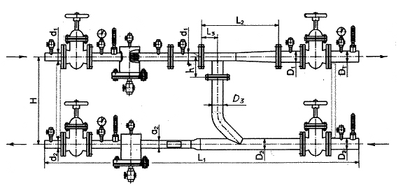
also in modern systems a thermal energy metering unit can be installed. From the name you can understand that he is responsible for accounting for heat consumption in the house. If this device is missing, the savings will not be visible. Most owners of private houses and apartments seek to install meters for electricity and water, because they have to pay much less.
Node characteristics and features of work
According to the diagrams, it can be understood that the elevator in the system is needed to cool the superheated coolant. In some designs there is an elevator that can also heat water. Especially such a heating system is relevant in cold regions. The elevator in this system starts only when the cooled liquid is mixed with hot water coming from the supply pipe.  Scheme. The number "1" indicates the supply line of the heating network. 2 is the return line of the network. Under the number "3" is the elevator, 4 - the flow regulator, 5 - the local heating system.
According to this scheme, it can be understood that the node significantly increases the efficiency of the entire heating system in the house. It works at the same time as circulation pump and mixer. As for the cost, the node will cost quite cheaply, especially the option that works without electricity.
But any system has its drawbacks, and was no exception:
- Separate calculations are required for each element of the elevator.
- Compression drops should not exceed 0.8-2 bar.
- Inability to control high temperature.
How is the elevator
AT recent times elevators appeared in public utilities. Why did you choose this equipment? The answer is simple: elevators remain stable even when there are drops in the hydraulic and thermal conditions. The elevator consists of several parts - a vacuum chamber, a jet device and a nozzle. You can also hear about the "elevator piping" - we are talking about valves, as well as measuring instruments that allow you to maintain normal work the entire system.
As mentioned above, elevators equipped with an electric drive are used today. Due to the electric drive, the mechanism automatically controls the diameter of the nozzle, as a result, the temperature is maintained in the system. The use of such elevators helps to reduce energy bills. 
The design is equipped with a mechanism that rotates due to an electric drive. Older versions use a toothed roller. A mechanism is designed to ensure that the throttle needle can be moved in longitudinal direction. Thus, the diameter of the nozzle changes, after which it is possible to change the flow rate of the heat carrier. Due to this mechanism, the consumption of network fluid can be reduced to a minimum or increased by 10-20%.
Possible malfunctions
A common malfunction can be called a mechanical failure of the elevator. This may occur due to an increase in the diameter of the nozzle, defects in the valves or clogging of the sump. It is quite simple to understand that the elevator is out of order - there are noticeable temperature drops of the heat carrier after and before passing through the elevator. If the temperature is low, then the device is simply clogged. In case of large differences, repair of the elevator is required. In any case, if a malfunction occurs, diagnostics are required.
The elevator nozzle becomes clogged quite often, especially in areas where the water contains many additives. This element can be dismantled and cleaned. In the case when the nozzle diameter has increased, an adjustment is necessary or complete replacement this element. 
Other malfunctions include overheating of devices, leaks and other defects inherent in pipelines. As for the sump, the degree of clogging can be determined by the indicators of pressure gauges. If the pressure increases after the sump, then the element needs to be checked.
K category: Water supply and heating
Control units for local heating systems
From external heating networks, water enters buildings to control units (Fig. 255), installed at the inputs, with the help of which they turn on, turn off, control and regulate local systems.
Gate valves are installed at the entrance to the building on the supply and return pipelines to disconnect the local system from outdoor network. To start the system in winter period in order to avoid freezing of the pipeline from the heating main to the control unit, a bypass line is arranged, which operates during the start-up of the system in winter. Water with a temperature above 100 °C from the heating network enters the water jet elevator, where it is mixed with part of the return water from the local heating system.
The required temperature of the mixed water entering the system is achieved by adjusting the valves at the elevator. Return water, not mixed with the hot one, is sent from the system through the water meter to the heating network. The water meter is connected to the heat meter by fittings.
The water meter is installed on the return line, in which the coolant has more low temperature, which ensures normal working conditions.
To control the water temperature, three thermometers are installed: before the elevator, after the elevator and on the return line.
The pressure is controlled by three pressure gauges set at the same level. Three-way valves are located under the manometers. The pressure loss in the system and the resistance of the elevator are at least 8-10 m of water. Art.
The input is equipped with a regulator that automatically maintains constant flow water. In some cases, a backwater regulator is also installed.
Rice. 1. Control unit for local heating systems: 1 -- three-way valve, 2 - gate valves, 3 - plug valves, 4, 12 - mud collectors, 5 - check valve, 6 - throttle washer, 7 - fitting for heat meter, 8 - thermometer, 9 - pressure gauge, 10 - elevator, 11 - heat meter, 13 - water meter, 14 - water flow regulator, 15 - backwater regulator, 16 -. valves, 17 - bypass line
To trap the dirt that has fallen into the network, mud collectors are installed with drain plug valves. To regulate the resistance, a check valve and a throttle washer are installed after the regulator.
Automated control unit of the heating system is a kind of individual heat point and is designed to control the parameters of the coolant in the heating system, depending on the outdoor temperature and the operating conditions of buildings.
The unit consists of a corrective pump, an electronic temperature controller that maintains a predetermined temperature schedule, and differential pressure and flow regulators. And structurally, these are pipeline blocks mounted on a metal support frame, including a pump, control valves, elements of electric drives and automation, instrumentation, filters, mud collectors.
AT automated control unit for the heating system control elements from Danfoss were installed, the pump was installed from Grundfoss. The complete set of control units is made taking into account the recommendations of Danfoss specialists, who provide consulting services in the development of these units.
The node works as follows. When conditions occur when the temperature in the heating network exceeds the required one, the electronic controller turns on the pump, and it adds as much coolant from the return pipe to the heating system as necessary to maintain the set temperature. The hydraulic water regulator, in turn, is covered, reducing the supply of network water.
Working mode automated heating system control unit in winter round the clock, the temperature is maintained in accordance with temperature chart corrected for return water temperature.
At the request of the customer, a mode for reducing the temperature in heated rooms at night, on weekends and holidays can be provided, which provides significant savings.
A decrease in air temperature in residential buildings at night by 2-3°C does not worsen sanitary and hygienic conditions and at the same time saves 4-5%. In industrial and administrative-public buildings, heat savings by lowering the temperature during non-working hours is achieved to an even greater extent. The temperature during non-working hours can be maintained at the level of 10-12 °C. The total heat savings with automatic control can be up to 25% of the annual consumption. During the summer period, the automated node does not work.
A promising approach to resolving the current situation is the commissioning of automated heat points with a commercial heat metering unit, which reflects the actual consumption of thermal energy by the consumer and allows you to track the current and total heat consumption for a given period of time.
Target audience, solutions:
Commissioning of automated heat points with a commercial heat metering unit allows solving the following tasks:
JSC Energo:
- increased reliability of equipment operation, as a result, reduction of accidents and means for their elimination;
- accuracy of heating system adjustment;
- reducing the cost of water treatment;
- reduction of repair sites;
- high degree of dispatching and archiving.
housing and communal services, municipal management enterprise (MUP), management company (MC):
- no need for constant plumbing and operator intervention in the operation of the heating point;
- decrease service personnel;
- payment for actual consumption thermal energy no loss;
- reduction of losses for feeding the system;
- release of free space;
- durability and high maintainability;
- comfort and ease of heat load management. Design organizations:
- strict compliance with the terms of reference;
- wide selection circuit solutions;
- high degree of automation;
- big choice complete set of heating points engineering equipment;
- high energy efficiency. Industrial enterprises:
- a high degree of redundancy, especially important for continuous technological processes;
- accounting and exact observance of high-tech processes;
- the possibility of using condensate in the presence of process steam;
- temperature control by workshops;
- adjustable selection of hot water and steam;
- decrease in recharge, etc.
Description
Heat points are divided into:
- individual heat points (ITP) used to connect heating, ventilation, hot water supply systems and technological heat-using installations of one building or part of it;
- central heating substations (CHPs) performing the same functions as ITPs for two or more buildings.
One of the priority activities of CJSC "TeploKomplektMontazh" is the manufacture of block automated heat points using modern technologies, equipment and materials.
More and more wide application they find heat points manufactured on a single frame in a modular design of high prefabrication called block, hereinafter BTP. BTPs are a complete factory product, designed to transfer thermal energy from a thermal power plant or boiler house to a heating, ventilation and hot water supply system. The BTP includes the following equipment: heat exchangers, controller (electrical control panel), direct-acting regulators, control valves with electric drive, pumps, instrumentation (KIP), shut-off valves, etc. Instrumentation and sensors provide measurement and control of coolant parameters and issue signals to the controller about parameters going beyond the limits allowed values. The controller allows you to control the following BTP systems in automatic and manual mode:
Regulation of flow, temperature and pressure of the heat carrier from the heating network in accordance with the technical conditions of heat supply;
Temperature control of the heat carrier supplied to the heating system, taking into account the outdoor temperature, time of day and working day;
Heating water for hot water supply and maintaining the temperature within the limits of sanitary standards;
Protection of the circuits of the heating system and hot water supply from emptying during scheduled shutdowns for repairs or accidents in the networks;
Accumulation DHW water, which allows to compensate for peak consumption during peak hours;
- frequency regulation of the drive by pumps and protection against "dry running";
- control, notification and archiving of emergency situations, etc.
The performance of the BTP varies depending on the ones used in each separate case connection schemes for heat consumption systems, type of heat supply system, as well as specific specifications project and customer requirements.
Schemes of BTP connections to heat networks
On fig. 1-3 shows the most common schemes for connecting heat points to heat networks.


Application of shell and tube or plate heat exchangers in BTP?
The substations of most buildings are usually equipped with shell-and-tube heat exchangers and direct-acting hydraulic regulators. In most cases, this equipment has exhausted its resource, and also operates in modes that do not correspond to the calculated ones. The latter circumstance is due to the fact that the actual heat loads are currently maintained at a level significantly lower than the design one. The control equipment does not perform its functions in case of significant deviations from the design mode.
When reconstructing heat supply systems, it is recommended to use modern equipment, which is compact and provides for work in full automatic mode and providing savings of up to 30% of energy, compared with the equipment used in the 60-70s. In modern heat points, an independent scheme for connecting heating and hot water supply systems is usually used, made on the basis of plate heat exchangers. To control thermal processes are used electronic regulators and specialized controllers. Modern plate heat exchangers are several times lighter and smaller than shell-and-tube heat exchangers of the same capacity. The compactness and low weight of plate heat exchangers greatly facilitate installation, maintenance and Maintenance heating equipment.
|
|  |

Recommendations for the selection of shell-and-tube and plate heat exchangers are given in SP 41-101-95. Design of thermal points. The calculation of plate heat exchangers is based on a system of criterion equations. However, before proceeding with the calculation of the heat exchanger, it is necessary to calculate the optimal distribution of the DHW load between the stages of the heaters and temperature regime each stage, taking into account the method of regulating the heat supply from the heat source and the schemes for connecting DHW heaters.
The company CJSC "TeploKomplektMontazh" has its own proven program of thermal and hydraulic calculation, allowing you to select lamellar brazed and collapsible heat exchangers Funke, which fully meet the requirements of the customer.
BTP produced by CJSC "TeploKomplektMontazh"
Collapsible plate heat exchangers Funke who excelled in hard Russian conditions. They are reliable, easy to maintain and durable. Heat meters are used as a unit for commercial heat metering, which have an interface output to the upper control level and allow reading the consumed amount of heat. To maintain the set temperature in the hot water supply system, as well as to regulate the temperature of the coolant in the heating system, a two-circuit regulator is used. The control of the pumps, data collection from the heat meter, control of the regulator, control of the general condition of the BTP, communication with the upper level of control (dispatching) is taken over by the controller, which is compatible with a personal computer.
The regulator has two independent circuits for regulating the temperature of heat carriers. One provides temperature control in the heating system depending on the schedule, taking into account the outdoor temperature, time of day, day of the week, etc. The other maintains the set temperature in the hot water supply system. You can work with the device both locally, using the built-in keyboard and display panel, and remotely via the interface communication line.
The controller has several discrete inputs and outputs. Discrete inputs are used to receive signals from sensors related to pump operation, penetration into the premises of the BTP, fire, flooding, etc. All this information is delivered to the upper dispatching level. Through the discrete outputs of the controller, the operation of pumps and regulators is controlled according to any user algorithms specified at the design stage. It is possible to change these algorithms from the top management level.
The controller can be programmed to work with a heat meter, providing data on heat consumption in control room. Through it, communication with the regulator is carried out. All devices and communication equipment mounted in small closet management. Its placement is determined at the design stage.

In the vast majority of cases, when reconstructing old heat supply systems and creating new ones, it is advisable to use BTP. BTP, being assembled and tested in the factory, are distinguished by reliability. Installation of equipment is simplified and cheaper, which ultimately reduces the overall cost of renovation or new construction. Each BTP project of CJSC "TeploKomplektMontazh" is individual and takes into account all the features of the customer's heating point: structure heat consumption, hydraulic resistance, schematic solutions of heat points, permissible pressure losses in heat exchangers, room dimensions, quality tap water and much more.
Types of activity of CJSC "TeploKomplektMontazh" in the field of BTP
CJSC "TeploKomplektMontazh" performs the following types works in the field of BTP:
- drafting terms of reference for the BTP project;
- BTP design;
- agreement technical solutions on BTP projects;
- engineering support and project support;
- selection of the optimal option for equipment and automation of the BTP, taking into account all the requirements of the customer;
- installation of BTP;
- conducting commissioning;
- putting the heat point into operation;
- warranty and post-warranty maintenance of the heating point.
CJSC "TeploKomplektMontazh" successfully develops energy efficient systems heat supply, engineering systems, and is also engaged in design, installation, reconstruction, automation, provides warranty and post-warranty maintenance of the BTP. A flexible system of discounts and a wide range of components distinguish BTP CJSC "TeploKomplektMontazh" from others. BTP CJSC "TeploKomplektMontazh" is a way to reduce energy costs and ensure maximum comfort.
Sincerely, ZAO
"TeplokomplektMontazh"


 Constellation Scorpio description")


