Automated control node heating system is a kind of individual heat point and is designed to control the parameters of the coolant in the heating system, depending on the outdoor temperature and the operating conditions of buildings.
The unit consists of a corrective pump, an electronic temperature controller that maintains a predetermined temperature schedule, and differential pressure and flow controllers. And structurally, these are pipeline blocks mounted on a metal support frame, including a pump, control valves, elements of electric drives and automation, instrumentation, filters, mud collectors.
In the automated control unit, Danfoss control elements are installed, the pump is Grundfoss. The complete set of control units is made taking into account the recommendations of Danfoss specialists, who provide consulting services in the development of these units.
The node works as follows. When conditions occur when the temperature in the heating network exceeds the required one, electronic regulator turns on the pump, and it adds to the heating system as much coolant from the return pipe as necessary to maintain the set temperature. The hydraulic regulator, in turn, is covered, reducing the supply of network water.
Working mode automated control unit in winter, round the clock, the temperature is maintained in accordance with the temperature schedule with correction for the return water temperature.
At the request of the customer, a mode for reducing the temperature in heated rooms at night, on weekends and holidays which results in significant savings.
Lowering the air temperature in residential buildings at night by 2-3 °C does not worsen sanitary and hygienic conditions and at the same time saves 4-5%. In industrial and administrative-public buildings, heat savings by lowering the temperature during non-working hours is achieved to an even greater extent. The temperature during non-working hours can be maintained at the level of 10-12 °С. The total heat savings with automatic control can be up to 25% of the annual consumption. During the summer period, the automated node does not work.
Energy saving is especially important, because. it is with the introduction of energy-efficient measures that the consumer achieves maximum savings.
The range of control units for the heating system
| Q, Gcal/h | dpipe, mm | |
| 1 | 0,15 | 50 |
| 2 | 0,30 | 50 |
| 3 | 0,45 | 65 |
| 4 | 0,60 | 80 |
| 5 | 0,75 | 80 |
| 6 | 0,90 | 80 |
| 7 | 1,05 | 80 |
| 8 | 1,20 | 100 |
| 9 | 1,35 | 100 |
| 10 | 1,50 | 100 |
The share of heating costs is predominant in utility bills throughout our country. At the same time, in northern regions, as well as where imported fuel oil is used as fuel, thermal energy is especially expensive. For this reason, the issue of economical consumption and reasonable use of thermal energy is one of the most urgent today.
As you know, savings start with accounting. Today, meters of thermal energy supplied to an apartment building are installed almost everywhere. Statistics show that this simple measure has reduced heating costs by 20% and sometimes even 30%. But this is not enough, we need to move on and the vector of this movement should be directed towards apartment-by-apartment heat metering and reducing energy consumption, depending on the reduction in demand for it.
To do this, it will be necessary to reconstruct the elevator input and install a control unit for the heat supply system with automatic regulation of its operation depending on the outdoor temperature. It is also necessary to install pumps with frequency regulation of their operation. Most efficient system will be when installing a temperature control sensor and a meter for accounting for the consumption of thermal energy on each heating radiator.
Of course, this will require cash, which, by preliminary calculations, should pay off within two years of operation of the system. You can use funds from the federal program to improve the efficiency of the use of energy resources, take a loan and repay it at the expense of monthly receipts from residents, highlighting separately the cost of the reconstruction of the heating system. You can simply "chip" and thereby stop throwing your own money into environment together with irrationally used thermal energy.
The main thing is to understand that the heating system that exists today, especially during the off-season, is like a fire lit on the balcony: it warms, but not what is needed.
Perfect option
The ideal option heating system for the consumer is heating network, which automatically maintains the set temperature in each room. At the same time, for residents, the motivation for its installation and use should be not only comfortable conditions residence (you can simply adjust the temperature by opening balcony door or a window to the street), but also a reduction in heating bills.
For this you need apartment system metering of thermal energy consumption. Sales companies insist that in our country, with its traditional vertical distribution of the heating system, it is impossible to install a heat meter for each apartment, but at the same time it is overlooked (or simply there is no desire to see and take it into account) that heat meters can be installed in each heating radiator, while not changing the two-pipe or one-pipe vertical heat distribution to a horizontal one.
When calculating for heat, it is enough to sum up the readings of all meters. Even an elementary school student can handle it.
Individual metering of thermal energy will allow you to consciously save heat by stopping its supply to those rooms where no one lives temporarily or simply preferring to be in a cool room. To do this, you can close the taps installed on each radiator.
But there is another way to regulate heat consumption: using radiator thermostat consisting of a valve and a thermostatic head. The principle of operation of the system is simple: the movement of the valve embedded in the pipe is controlled by thermostatic head, which reacts to changes in the temperature in the room: hot, the valve closes the pipe, cold, on the contrary, opens. At the same time, using manual control, you can set the device as you wish: like it to be hot, set the maximum temperature on the controller that you want to get in the room.
There are thermostats with which you can adjust the temperature in the room depending on the time of day: no one is at home during the day, you can turn off the heating, turn it on in the evening.
It would seem that everything is simple: meters can be installed in each apartment, the amount of heat energy can be increased or decreased, and heating fees can be saved. But at the same time, the system for regulating the distribution of thermal energy throughout the house, that is, the traditional elevator input, is overlooked.
The principle of operation of the hydraulic elevator
The coolant is supplied to the hydraulic elevator from main pipeline. Its pressure is regulated using a conventional valve. At the same time, the temperature of the network water is so high that it cannot be supplied directly to consumers, so the network water in the hydraulic elevator is mixed with the already cooled return flow.
If the coolant makes a cycle of movement through the heating system and at the same time does not consume the supply of thermal energy, which will certainly happen when the heating devices are turned off, the elevator will receive hot water from the network and hot water from the return pipeline.
The hydraulic elevator does not have feedback with the main pipeline and cannot reduce the pressure of network water. As a result, too hot water will be sent to consumers whose heating devices are not blocked and operate at full capacity, which will lead to damage to the equipment.
At the same time, the heat energy meter will not record a decrease in heat consumption, and the sales company will note overheating and impose penalties. It turns out that all efforts to reduce heating costs were made in vain.
What to do
Need a heating point with automatic system network water supply regulation

1. Hydraulic elevator
2. Electric drive
3. Control system
4. Temperature sensor
5. Temperature sensor of the heating medium in the supply pipeline
6. Return temperature sensor
It uses a heat exchanger in which network water and water from the main pipeline are mixed. It is this "mixture" that is supplied to the heating system. Its temperature is also measured when allowable value the supply is blocked main water, which leads to a reduction in the consumption of thermal energy.
As a result, the consumption of thermal energy can be controlled. 
Description:
Such measures are the installation of automated control units for heating systems (hereinafter - ACU) instead of thermal or elevator units, the installation of balancing valves on the risers of heating systems and thermostatic valves on connections to heaters.
Mistakes in the implementation of automated control units for heating systems in Moscow (2008–2009)
A. M. Filippov, Head of the Energy Saving Control Inspectorate of the State Housing Inspectorate of Moscow
With the adoption of Federal Law No. 261-FZ dated November 23, 2009 “On Energy Saving and Energy Efficiency Improvement and on Amendments to Certain legislative acts Russian Federation» the importance of energy saving in residential buildings is growing, especially measures that allow not only automating, but also reducing the consumption of heat energy by apartment buildings, as well as optimizing the distribution of heat between consumers in the house. Such measures are the installation of automated control units for heating systems (hereinafter referred to as ACU) instead of thermal or elevator units, the installation of balancing valves on the risers of heating systems and thermostatic valves on the connections to heating devices.
Prerequisites for the introduction of ACU
For the first time, the concept of ACU appeared back in 1995, when MNIITEP developed and approved the concept of "Modern Energy-Saving Heat Supply and Heating Systems for Buildings in the Mass Construction of Moscow" and a program for its implementation. Subsequently, the introduction of ACU was prescribed in the new edition of MGSN 2.01–99 “Energy Saving in the Building”, then on April 27, 2002, a meeting of the Complex of Architecture of the City of Moscow was held, at which, among others, they considered the issue “On standard technical solutions for equipping buildings under construction residential buildings automated control units of heating systems.
In 2008, the MoszhilNIIproekt State Unitary Enterprise, together with Danfoss LLC, compiled the album "Automated Control Units" using technical solutions standard project, and in May 2008, the heat supply organization OJSC MIPC held two meetings with the participation of design and contracting organizations for the installation of ACU on the design and development of technical conditions for linking a typical project for the installation of ACU during the overhaul of residential buildings of the 2008–2014 program.
Since August 2008, the mass introduction (installation) of ACU began in residential buildings instead of elevator and heating units, and at present in Moscow the number of residential buildings with installed automatic control units reaches 1000 buildings, which is approximately 3% of residential buildings in the city.
The principle of operation and the benefits of using ACU
What is the ACU, the device and the principle of its operation were described repeatedly in the works of M. M. Grudzinsky, S. I. Prizhizhetsky and V. L. Granovsky, including in. In addition, a similar principle of operation of the equipment is used in the central heating station of OAO MIPC (previously - in the heat points of the State Unitary Enterprise Mosgorteplo) in the system automatic regulation dependent heating system (SARZSO), but only for transitional modes in autumn and spring.
In short, ACU is a set of devices and equipment that provides automatic control of the temperature and flow rate of the coolant at the inlet to each building exactly in accordance with the specified for this building temperature graph or according to the needs of residents.
The advantage of ACU in comparison with thermal and elevator units that have a fixed cross section of the passage opening (elevator nozzle, throttle diaphragm), through which the coolant enters the house heating system, is the possibility of changing the amount of coolant supplied depending on the water temperature in the supply and return pipelines of the system heating with outdoor temperature correction in accordance with the temperature curve.
Unlike the elevator units installed on each section of the house, the ACU is usually mounted one per building (if there are 2 thermal inputs in the house, then 2 ACUs are installed), while the connection is made after the metering unit for the thermal energy of the heating system (if any ).
Schematic diagram and view of ACU in axonometry is shown in fig. 1, 2 (based on the materials of Danfoss LLC). Possible design options, due to the scheme of connection to the heating network, hydraulic modes at the thermal input, specific design building heating systems and operating conditions (12 standard solutions in total).
Figure 2. |
An exemplary scheme of the ACU provides: 1 - electronic unit (control panel); 2 – outdoor air temperature sensor; 3 – coolant temperature sensors in the supply and return pipelines; 4 – flow regulator valve with gear drive; 5 – differential pressure regulator valve; 6 - filter; 7- circulation pump; 8 – check valve.
As can be seen from the diagram, ACU basically consists of three parts: network, circulation and electronic.
The network part of the ACU includes a coolant flow regulator valve with a gear drive, a differential pressure regulator valve with a spring regulating element and a filter.
The circulation part of the ACU includes a circulation (mixing) pump and a check valve. As mixing pumps, two Grundfos pumps (or other types of pumps that meet the requirements of the ACU) are installed, which operate alternately on a timer with a cycle of 6 hours. The pumps are controlled by a signal from a differential pressure sensor installed on the pumps.
The electronic part of the ACU includes an electronic unit (control panel) that provides automatic control thermal mechanical and pumping equipment in order to maintain the set temperature graph and hydraulic regime in the building heating system, an ECL card (designed for programming the thermal mode controller), an outdoor temperature sensor (installed on the north side of the building facade), coolant temperature sensors in the supply and return pipelines and a valve gear motor regulation of the coolant flow in the AC network part.
Mistakes in the implementation of ACU
The main topic of this article is the mistakes made during the planning of work, design and installation of ACU in Moscow, which nullified all the work done and did not allow to obtain the planned indicators for energy efficiency and energy saving. For a year and a half, the installed AHUs were practically not used for their intended purpose or were used inefficiently, expensive equipment often stood idle in a disconnected state, and the coolant entered the house heating systems through undismantled elevators.
Of course, many of the mistakes were later corrected, and the work of the AMU was adjusted, but mistakes could have been avoided if the work was properly organized at all stages of the process.
So what were those mistakes?
1. At the stage of planning and organization of work.
When choosing a technical solution, in violation of the requirements of MGSN 2.01–99 “Energy Saving in Buildings” (clause 4.2.1.), A technical and economic comparison of the options was not carried out: 1) installation of ACU from distribution networks of central heating stations or 2) installation of ITP from city main heat pipelines and plumbing networks. As a result, during the installation of the automatic control unit, the functions of the equipment installed in the central heating station were duplicated, which is contrary to the "Rules technical operation thermal power plants” of Rostekhnadzor of the Russian Federation (clause 9.1.2.), and the installation of automatic control units and balancing valves led to an increase in hydraulic resistance in the system and the need to replace (reconstruct) the thermal and mechanical equipment of the CHP. However, the reconstruction of the central heating substation was not envisaged, and the ACU was introduced not by the cluster method, starting from the end houses, but in a non-complex manner, only in individual buildings at the beginning or in the middle of the connection to the central heating substation. As a result, the non-complex installation of the ACU violated the established hydraulic and thermal balance in the intra-quarter heating networks, led to a deterioration in the operation of the heating systems of most of the attached buildings and necessitated expensive thermal adjustment (with the calculation of the diameters of the elevator nozzles and throttle diaphragms, their installation on the input distribution nodes and subsequent adjustment (replacement) during operation in heating period.
2. At the design stage:
- there were no working projects, often instead of working projects, copies from a standard project were used without calculations, selection and binding of equipment to local conditions, which led to erroneous decisions when choosing and installing equipment and, as a result, to violations of heat supply regimes during its operation;
- the selected installation schemes for the ACU did not meet the requirements, which immediately had a negative impact on the heat supply. For example, in three residential buildings of ZAO, as a result of the dismantling of the elevator unit and the use of dependent system heating of the AUU circuit, intended for independent systems without a mixing unit, the design temperature schedule of the system operation (95–70 °С) was violated and the primary superheated coolant with a temperature schedule (150/70 °С) entered the heating devices, which led to overheating of the nearest along the course of the heat carrier of residential premises and to the violation of the circulation of the heat carrier in the end risers (underheating of the premises located on the end risers). Operation of the system in this mode was fraught with burns of residents when touching devices and pipelines. Only timely intervention helped eliminate this error before the onset of cold weather;
- issued specifications(TS) did not correspond to the actual parameters: for example, the 150/70 °С schedule was indicated in the TS and the project instead of the actual 105/70 °С, which led to the wrong choice of the ACU scheme. Also, when issuing technical conditions for the ACU, it was not taken into account that in the course of overhaul heating systems were reconstructed (schemes were changed from one-pipe to two-pipe, diameters of distributing pipelines and risers, heating areas of heating devices, etc.), while the calculation of the AC was made for the heating system before the reconstruction.
3. At the stage of installation and commissioning:
- the time for installation was mistakenly chosen: ACUs were often mounted already in winter period after the completion of other works, which led to complaints from residents about the untimely start of heat, frequent shutdowns of heating, violations of the temperature regime;
– in vain they refused to install ACU in cases when balancing valves were installed on the risers of central heating systems during the overhaul. Their installation led to a sharp increase in hydraulic resistance in the systems, and in the absence of ACU with pumping equipment and no work was done to replace pumps in the central heating substation in such residential buildings and neighboring houses in the heating period, problems with heat supply immediately arose;
– outdoor air temperature sensors were not mounted on the north side of the building, which led to incorrect setting of the thermal regime due to the influence solar radiation on the sensor (its heating);
- the work of the AMU was carried out in a freelance manual mode and was not transferred to auto mode;
– documents and ECL cards were missing due to the fact that the installer did not transfer them management company;
– there was no backup power supply for the AC, which in the event of a power outage could lead to a shutdown of the central heating system;
- adjustment and adjustment work and noise reduction measures were not carried out;
- there was no maintenance of the ACU.
As a result of these errors and violations, in houses with installed ACs, there were numerous complaints from residents about the non-heating of the heating system and the noise from the operation of the equipment.
All of the above became possible due to the poor organization of work, the lack of proper control by the customer over all stages of the process of introducing ACU. The author hopes that the published article will help to avoid such mistakes in the future both in Moscow and in other cities.
When introducing ACU, it is necessary to clearly organize the work of design organizations, relevant construction and installation and repair and maintenance services, carefully check the issued technical specifications for compliance with actual data, conduct technical supervision at each stage of work, and immediately after installation, begin maintenance of the ACU by specialized organization. Otherwise, downtime of the expensive ACU equipment or its unskilled maintenance will lead to failure, loss of technical documentation and other negative consequences.
Effective use of ACU
The use of ACU is most effective in the following cases:
- in houses with subscribed elevator nodes of the heating system, directly connected to the city's main heating networks;
– in end houses linked to the central heating substation with insufficient pressure drop in the central heating system with obligatory installation central heating pumps;
- in houses with gas water heaters(with decentralized hot water supply) and central heating.
ACU should be installed in a complex, cluster method, covering all, without exception, residential and non-residential buildings connected to the central heating substation.
Installation and commissioning of the heating system and ACU equipment must be carried out simultaneously.
It should be noted that along with the installation of ACU, the following measures are quite effective:
– transfer of the central heating substation with a dependent scheme for connecting heating systems to an independent one with installation in heating point membrane expansion tank;
- installation in the central heating station with a dependent connection scheme of equipment for automatic control of heat supply (SAR ZSO), similar to AUU;
- adjustment of intra-quarter central heating networks with the installation of design nozzles for elevators and throttle diaphragms at the input distribution units of buildings;
– transfer of dead-end hot water supply systems to circulation schemes.
In general, the operation of exemplary ACUs has shown that the use of ACUs in conjunction with balancing valves on the risers of the central heating system, thermostatic valves on each heater and holding warming measures allows you to save up to 25-37% of thermal energy and provide comfortable living conditions in every room.
Literature
1. Grudzinsky M. M., Prizhizhetsky S. I. Energy efficient heating systems // ABOK. - 1999. - No. 6.
2. Granovsky V. L., Prizhizhetsky S. I. Heating system for residential buildings of mass construction and reconstruction with integrated automation of heat consumption // AVOK. - 2002. - No. 5.
K category: Water supply and heating
Control units for local heating systems
From external heating networks, water enters buildings to control units (Fig. 255), installed at the inputs, with the help of which they turn on, turn off, control and regulate local systems.
Gate valves are installed at the entrance to the building on the supply and return pipelines to disconnect the local system from outdoor network. To start the system in winter, in order to avoid freezing of the pipeline from the heating main to the control unit, a bypass line is arranged, which operates during the start-up of the system in winter. Water with a temperature above 100 °C from the heating network enters the water jet elevator, where it is mixed with part of the return water from the local heating system.
The required temperature of the mixed water entering the system is achieved by adjusting the valves at the elevator. Return water, not mixed with the hot one, is sent from the system through the water meter to the heating network. The water meter is connected to the heat meter by fittings.
The water meter is installed on the return line, in which the coolant has more low temperature, which ensures normal working conditions.
To control the water temperature, three thermometers are installed: before the elevator, after the elevator and on the return line.
The pressure is controlled by three pressure gauges set at the same level. Three-way valves are located under the manometers. The pressure loss in the system and the resistance of the elevator are at least 8-10 m of water. Art.
The input is equipped with a regulator that automatically maintains constant flow water. AT individual cases also install a pressure regulator.
Rice. 1. Control unit for local heating systems: 1 -- three-way valve, 2 - gate valves, 3 - plug valves, 4, 12 - mud collectors, 5 - check valve, 6 - throttle washer, 7 - fitting for heat meter, 8 - thermometer, 9 - pressure gauge, 10 - elevator, 11 - heat meter, 13 - water meter, 14 - water flow regulator, 15 - backwater regulator, 16 -. valves, 17 - bypass line
To trap the dirt that has fallen into the network, mud collectors are installed with drain plug valves. To regulate the resistance, a check valve and a throttle washer are installed after the regulator.
In any building, including a private house, there are several life support systems. One of them is the heating system. Can be used in private homes different systems, which are selected depending on the size of the building, the number of floors, climate characteristics and other factors. In this material, we will analyze in detail what a heating unit is, how it works and where it is used. If you already have an elevator assembly, then it will be useful for you to learn about defects and how to eliminate them. This is what a modern elevator unit looks like. Shown here is an electrically driven unit. Other types of this product are also found.
In simple words, a thermal unit is a complex of elements that serve to connect a heating network and heat consumers. Surely readers have a question whether it is possible to install this node on their own. Yes, you can if you can read diagrams. We will consider them, and one scheme will be analyzed in detail.
Principle of operation
To understand how the node works, it is necessary to give an example. To do this, we will take a three-story house, since the elevator unit is used specifically in high-rise buildings. The main part of the equipment that belongs to this system is located in basement. The diagram below will help us better understand the work. We see two pipelines:
- Serve.
- Back.

Now you need to find on the diagram thermal camera through which water is sent to the basement. You can also notice the shut-off valves, which should in without fail stand at the entrance. The choice of fittings depends on the type of system. Gate valves are used for standard construction. But if it's about complex system in a multi-storey building, then the masters recommend taking steel ball valves.
When connecting a thermal elevator unit, it is necessary to adhere to the norms. First of all, this concerns temperature conditions in boiler rooms. During operation, the following indicators are allowed:
- 150/70°C;
- 130/70°C;
- 95(90)/70°C.
When the temperature of the liquid is in the range of 70-95°C, it begins to be evenly distributed throughout the system due to the operation of the collector. If the temperature exceeds 95 ° C, the elevator unit starts to work to lower it, since hot water can damage the equipment in the house, as well as the valves. That is why this type of construction is used in multi-storey buildings - it controls the temperature automatically.
Schema parsing
As you understand, the unit consists of filters, an elevator, a control measuring instruments and fittings. If you plan to independently engage in the installation of this system, then you should understand the scheme. A suitable example would be a high-rise building, in the basement of which there is always an elevator unit.
In the diagram, the elements of the system are marked with numbers:
1, 2 - these numbers indicate the supply and return pipelines that are installed in the heating plant.
3.4 - supply and return pipelines installed in the heating system of the building (in our case, this is a multi-storey building).
5 - elevator.
6 - filters are indicated under this number coarse cleaning, which are also known as mud diggers.
7 - thermometers
8 - manometers.
The standard composition of this heating system includes control devices, mud collectors, elevators and valves. Depending on the design and purpose, additional elements may be added to the node.
Interesting! Today in high-rise and apartment buildings can be found elevator nodes which are electrically powered. Such an upgrade is needed in order to regulate the diameter of the nozzle. Due to the electric drive, you can adjust the heat carrier.
It is worth saying that every year public utilities rise in price, this also applies to private houses. In this regard, system manufacturers supply them with devices aimed at saving energy. For example, now the circuit may contain flow and pressure regulators, circulation pumps, pipe protection and water treatment elements, as well as automation aimed at maintaining a comfortable mode. 
also in modern systems a thermal energy metering unit can be installed. From the name you can understand that he is responsible for accounting for heat consumption in the house. If this device is missing, the savings will not be visible. Most owners of private houses and apartments seek to install meters for electricity and water, because they have to pay much less.
Node characteristics and features of work
According to the diagrams, it can be understood that the elevator in the system is needed to cool the superheated coolant. In some designs there is an elevator that can also heat water. Especially such a heating system is relevant in cold regions. The elevator in this system starts only when the cooled liquid is mixed with hot water coming from the supply pipe. 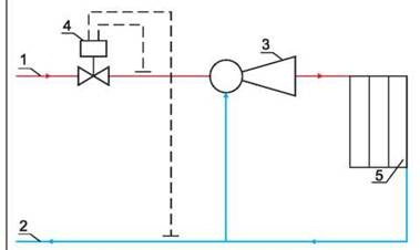 Scheme. The number "1" indicates the supply line of the heating network. 2 is the return line of the network. Under the number "3" is the elevator, 4 - the flow regulator, 5 - the local heating system.
According to this scheme, it can be understood that the node significantly increases the efficiency of the entire heating system in the house. It works simultaneously as a circulation pump and a mixer. As for the cost, the node will cost quite cheaply, especially the option that works without electricity.
But any system has its drawbacks, and was no exception:
- Separate calculations are required for each element of the elevator.
- Compression drops should not exceed 0.8-2 bar.
- Inability to control high temperature.
How is the elevator
AT recent times elevators appeared in public utilities. Why did you choose this equipment? The answer is simple: elevators remain stable even when there are drops in the hydraulic and thermal conditions. The elevator consists of several parts - a vacuum chamber, a jet device and a nozzle. You can also hear about the "binding of the elevator" - we are talking about stop valves, as well as measuring instruments that allow you to maintain normal work the entire system.
As mentioned above, elevators equipped with an electric drive are used today. Due to the electric drive, the mechanism automatically controls the diameter of the nozzle, as a result, the temperature is maintained in the system. The use of such elevators helps to reduce energy bills. 
The design is equipped with a mechanism that rotates due to an electric drive. Older versions use a toothed roller. A mechanism is designed to ensure that the throttle needle can be moved in longitudinal direction. Thus, the diameter of the nozzle changes, after which it is possible to change the flow rate of the heat carrier. Due to this mechanism, the consumption of network fluid can be reduced to a minimum or increased by 10-20%.
Possible malfunctions
A common malfunction can be called a mechanical failure of the elevator. This may occur due to an increase in the diameter of the nozzle, defects in the valves or clogging of the sump. It is quite simple to understand that the elevator is out of order - there are noticeable temperature drops of the heat carrier after and before passing through the elevator. If the temperature is low, then the device is simply clogged. In case of large differences, repair of the elevator is required. In any case, if a malfunction occurs, diagnostics are required.
The elevator nozzle becomes clogged quite often, especially in areas where the water contains many additives. This element can be dismantled and cleaned. In the case when the nozzle diameter has increased, an adjustment is necessary or complete replacement this element. 
Other malfunctions include overheating of devices, leaks and other defects inherent in pipelines. As for the sump, the degree of clogging can be determined by the indicators of pressure gauges. If the pressure increases after the sump, then the element needs to be checked.


