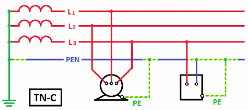
The TN-C grounding system, although it is still used in most apartment buildings, is outdated and is being actively replaced by TN-S or TN-C-S, which are more advanced in terms of protection. As a result, in electrical circuit diagrams N is used as the working zero, and the PE conductor is the protective zero that appears in the circuit after the PEN wire is separated, or taken directly from the ground loop.
Basic requirements for separating PEN conductor
Everything you need to know to competently carry out such work is spelled out in the provisions of the PUE. In particular, the need for such a connection is stated in paragraph 7.1.13

How the connection should look on the diagram is described in paragraph 1.7.135 - when in any place of the REN the conductor is divided into neutral and ground wires, their subsequent combination is not allowed.

Once separated, the tires are considered different and must be marked accordingly - zero in blue, and PE in yellow-green.
The jumper between the grounding bus and the neutral one is made of a material with a cross-section no smaller than the buses themselves, from which the PE and N wires go further. In this case, the protective conductor bus PE can be in contact with the transformer body, and the n bus is separately installed on insulators. The PE bus must be grounded - ideally there should be a separate circuit for it (PUE - 1.7.61).

When using RCD devices, the zero used to connect electrical equipment should not be in any way in contact with the zero that comes to the input machine and the meter. All these devices are connected using this principle.
Place of separation PEN conductor for PE and N wires, for a number of reasons, are carried out in the ASU, which is located at the entrance to an apartment or private building.
The PEN wire, which will be divided into working zero and grounding, must have a cross-section of at least 10 mm² if it is copper, and 16 squares if it is aluminum. Otherwise, division is prohibited.
Why you can’t separate the PEN conductor in the floor panel

This option cannot be used for a number of reasons:
- If we take into account exclusively the provisions of the PUE, they state that the separation of wires should occur at the input circuit breaker of an apartment building or a private detached house.
- Even if the apartment panel is considered a water machine (which is quite problematic to do), such a connection will be incorrect according to another requirement, namely, the PE conductor must be re-grounded, which is impossible to achieve in the floor panel.
- Even if you get clever and connect the grounding to the floor panel, there is another obstacle that threatens with large fines. The fact is that the electrical circuit during the construction of a house is approved by several authorities and its unauthorized change is a gross violation of all existing rules- essentially this is a change in the project according to which the house was connected to the network. Such matters should be handled exclusively by the organization serving this house or area.
Of course, if such an organization plans any work to separate the Pen conductor, then there is no point in fiddling with each floor panel separately. The best option would be to separate it at the input machine, which is what will be done.

An additional argument in favor of separating the Pen conductor on one circuit breaker in a residential building is the requirement of the PUE (clause 7.1.87) to install a potential equalization system in this place.
It is prohibited to do it in any other place, which means that the separation of the PEN conductor in the floor panel will in any case be done without observing all the necessary rules and precautions.
As a result, the only correct method for grounding a house is a collective appeal to the organization serving the house or area.
Why separate the PEN conductor if a jumper is placed between the PE and N buses - the “physics” of the process
A direct answer to this question is not given in the PUE and GOSTs - there are only recommendations “how to do it”, and “why” is not considered, most likely based on the assumption that it should be clear anyway. Therefore, all subsequent explanations should be taken as the opinion of the author, supported by the principles of connecting electrical wiring and the requirements of the PUE.
The main points here are:
- In any diagram that illustrates the division of a PEN conductor into PE and N, grounding is always placed first and a jumper goes from it to the working zero. This is the main requirement that must be taken into account when dividing a PEN conductor - on the contrary, this is never done under any circumstances.
- Even separately made grounding is most effective when connected through an RCD. Otherwise, even if the voltage from the body of the electrical device goes into the ground, there is still a risk of electric shock to a person, although much less.
- Any wire has a certain electrical resistance, accordingly, the longer the wire, the higher its resistance electric current.
To understand the “physics of the process” itself, we need to consider how they behave various schemes connections in the event of an emergency.
If there is no jumper and RCD circuit breaker, zero and ground are not connected
The phase enters the body of the device, from it it goes to the grounding bus, from it it goes into the ground along which it goes to the transformer substation.
If we take the average value of the resistance of the grounding device as 20 Ohms, the short circuit current will not be large enough to turn off the input circuit breaker. Respectively, electrical circuit will work until the damaged area burns out (in any case, there will be an increased temperature in this place and the wire will sooner or later deteriorate), or the damage develops into a full short circuit between phase and zero.
At best, a person may be noticeably “tickled” by an electric shock or the device may be damaged. At worst, the device may ignite and cause a fire.
If there is a jumper between zero and ground, there is no RCD
In this case, the circuit works in much the same way as if you simply put a PEN conductor into the house, with the only difference being that the person will be more protected due to grounding. This will happen precisely because of the length of the wire - since in any case the ASU is located at some distance from the apartment or house, the resistance of the wire must be taken into account.
When a phase is shorted to the body of the device, the leakage current will go to the grounding bus, where it will have only two outputs: part of it will go into the ground, and the other will return along the neutral wire, causing the incoming apartment circuit breaker to turn off.
That is, in in this case a jumper is needed for it to work circuit breaker ic switch.
If there are jumpers between PE and N, an RCD is installed
Since the neutral and ground wires have a certain resistance to electric current, it is clear that in this case the RCD will operate normally. If a short circuit occurs to the device body, the leakage current, first of all, goes through the wire to the RCD itself, and then goes to the ASU of the residential building. Here, again, it partially goes into the ground and partially comes back through the jumper, provoking the switching off of the input circuit breaker, but most likely it won’t come to this, since the RCD will trip earlier.
It is clear that in this case the jumper does not play a special role and is more of an extra reinsurance in that almost incredible case if the RCD circuit breaker does not work.
If there is no jumper between PE and N, an RCD is installed
Such a circuit will work in exactly the same way as if there was a jumper between the ground and the working zero. The only exception to this is the lack of insurance in case the RCD suddenly fails. Then the circuit will work according to the first option - the input circuit breaker may not work until the short circuit to the device body turns into a short circuit between phase and zero.
In fact, this scenario is practically impossible, because in fact such a connection is already a TN-S or even TT grounding circuit, which provides two-factor protection - without it, such a connection will not be accepted by energy supervision.
Features of PEN conductor separation at the entrance to a private house
To prevent the theft of electricity, a representative of the energy supervision may require that the PEN wire be connected directly to the meter and after it be divided into the lines of the PE conductor and the working N. In general, such a connection has the right to life, but it would be more correct to carry out the separation before meter and seal the input machine. In this case, the connection will be more reliable, the requirements of the PUE are met, and inspectors receive a line protected from unauthorized access.
For more information about PE and PEN conductors in a private home, watch this video:
As a result, when dividing a PEN conductor, it is enough to know and apply the requirements of the PUE, which provide comprehensive recommendations on this issue, regardless of the location and methods of connection.
The main task that must be solved when creating any electrical installation is to ensure its electrical safety. Regulatory documents provide for a set of measures to protect people and animals from electric shock, which should be taken into account when designing an electrical installation and its installation.
Under the guide in regulatory documentation refers to a conductive part (a part capable of conducting electric current), designed to conduct an electric current of a certain value. In electrical installations of buildings, linear, neutral, protective and some other conductors are used.
Protective conductors (PE) used in electrical installations to protect people and animals from electric shock. Protective conductors, as a rule, have an electrical connection with the grounding device and therefore, in normal operation, the building's electrical installations are at local ground potential.
Protective conductors are joined by exposed conductive parts with which a person has multiple electrical contacts.
Therefore, when installing the electrical installation of a building, it is very important not to confuse protective conductors with linear conductors in order to avoid a situation where a person who touches the body of, for example, a refrigerator to which a phase conductor is mistakenly connected will be shocked by an electric shock. Unique color identification of protective conductors is designed to dramatically reduce such errors.
In TN-C, TN-S, TN-C-S systems protective conductor connected to a grounded live part of the power source, for example, to the grounded neutral of a transformer. It's called neutral protective conductor.
They are also used in electrical installations of buildings. combined neutral protective and working conductors (PEN conductors), which combine the functions of both zero protective and neutral (zero working) conductors. According to their purpose, protective conductors also include grounding conductors and protective potential equalization conductors.

The neutral protective conductor (PE - conductor in the TN-S system) is the conductor connecting the grounded parts (open conductive parts) with a solidly grounded neutral point of a three-phase current power source or with a grounded output of a single-phase current power source, or with a grounded midpoint of a power source in networks DC.The neutral protective conductor should be distinguished from the neutral working and PEN conductors.
Zero working conductor(N - conductor in the TN-S system) - a conductor in electrical installations with voltage up to 1 kV, intended for powering electrical receivers connected to a solidly grounded neutral point of a generator or transformer in three-phase current networks, with a solidly grounded output of a single-phase current source, with a solidly grounded source point in DC networks current
Combined neutral protective and neutral working conductor (PEN - conductor in the TN-C system) - a conductor in electrical installations with voltage up to 1 kV, combining the functions of a neutral protective and neutral working conductor.
Grounding conductors are integral part grounding device of the building's electrical installation. They provide electrical connection a grounding conductor with a main grounding bus, to which, in turn, other protective conductors of the building's electrical installation are connected.
Protective grounding is an intentional electrical connection to the ground or its equivalent of metal non-current-carrying parts that may be energized due to a short circuit to the body and for other reasons (inductive influence of adjacent live parts, potential removal, lightning discharge, etc.). The equivalent of land can be river or sea water, coal in a quarry, etc.
Purpose protective grounding– eliminating the danger of electric shock in case of touching the electrical installation body and other non-current conductors metal parts energized due to a short circuit to the housing and for other reasons.
Potential equalization conductors are used in electrical installations of buildings and in buildings to perform potential equalization (connection between exposed and third-party conductive parts to ensure equipotentiality), which is usually intended to protect people and animals from electric shock. Therefore, in most cases these conductors are protective potential equalization conductors.
In accordance with the requirements of GOST R 50462 yellow color and green can be used in a yellow-green color combination, which is used exclusively to indicate protective (neutral protective) conductors (PE). Application for conductor identification yellow or green colors are not allowed if there is a danger of mixing the specified colors with a combination of yellow and green colors.
Based on the requirements set out in GOST R 50462, additions were made to the PUE establishing the following color coding electrical wiring conductors:
a two-color yellow-green combination should indicate protective and neutral protective conductors;
blue color should be used to identify neutral working conductors;
a two-color combination of yellow and green along the entire length of the conductor with blue marks at its ends, which are applied during installation, must be used to identify PEN conductors.
In accordance with the requirements of GOST R IEC 245-1, GOST R IEC 60227-1 and GOST R IEC 60173, the combination of yellow and green colors should be used only to indicate the insulated cable core that is intended for use as a protective conductor. The combination of yellow and green colors should not be used to identify other cable cores.
In all buildings, group network lines are laid from group, floor and apartment panels to lamps general lighting, plug sockets and stationary electrical receivers must be three-wire (phase - L, zero working - N and zero protective - PE conductors).
Combining zero working and zero protective conductors of different group lines is not allowed.
The neutral working and neutral protective conductors are not allowed to be connected to a common terminal. The selection of conductor cross-sections should be carried out in accordance with the requirements.
Single-phase two- and three-wire lines, as well as three-phase four- and five-wire lines when supplying single-phase loads, must have a cross-section of zero working N conductors equal to the cross-section of phase conductors.
Three-phase four- and five-wire lines when supplying three-phase symmetrical loads must have a cross-section of zero working N conductors equal to the cross-section of phase conductors, if the phase conductors have a cross-section of up to 16 mm2 for copper and 25 mm2 for aluminum, and for large cross-sections - at least 50% of the cross-section phase conductors, but not less than 16 mm2 for copper and 25 mm2 for aluminum.
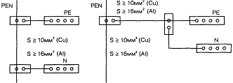
The cross-section of PEN conductors must be at least the cross-section of N conductors and at least 10 mm2 for copper and 16 mm2 for aluminum, regardless of the cross-section of the phase conductors.
The cross-section of PE conductors must be equal to the cross-section of phase conductors with a cross-section of the latter up to 16 mm2, 16 mm2 with a cross-section of phase conductors from 16 to 35 mm2 and 50% of the cross-section of phase conductors with larger cross-sections. The cross-section of PE conductors not included in the cable must be at least 2.5 mm2 - if there is mechanical protection and 4 mm2 - if there is none.
Connection diagrams for PE protective conductors
The combined neutral and working conductor PEN is divided into neutral protective PE and neutral working N conductors in the input device.
Used in drawings letter designations have the following meaning.
The first letter is the nature of the grounding of the power source: T – direct connection of one point of the current-carrying parts of the power source to the ground; N – direct connection of exposed conductive parts to the grounding point of the power source (usually the neutral is grounded in AC systems).
The following letters define the device of the zero working and zero protective conductors: S - the functions of the zero protective (PE) and zero working (N) are provided by separate conductors; C – the functions of the neutral protective and neutral working conductors are combined in one conductor (PEN conductor).
The neutral working and neutral protective conductors are not allowed to be connected to a common terminal. The meaning of this requirement is the need, in order to ensure, to maintain the connection of the protective conductor to grounding in the event of destruction (burnout) of the contact clamp.
Examples of connecting PE and N conductors to PEN in floor or apartment panels
Rules for implementing the potential equalization system
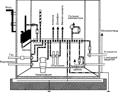
To ensure electrical safety conditions in a specific electrical installation, a potential equalization system is important. The rules for implementing the potential equalization system are defined by the IEC 364-4-41 standard and. These rules provide for connecting all conductors to be grounded to a common bus.
This solution allows you to avoid the flow of various unpredictable circulating currents in the grounding system, causing potential differences to occur on individual elements of the electrical installation.

An example of a potential equalization system in an electrical installation of a residential building
IN lately, with increasing equipment of modern residential buildings And industrial buildings various electrical appliances and the constant development of their electrical installations, phenomena of accelerated corrosion of pipelines of water supply and heating systems have increasingly begun to be observed. In a short time - from six months to two years - point fistulas form on both underground and overhead pipes, which quickly increase in size. The cause of accelerated pitting corrosion of pipes in 98% of cases is the flow of stray currents through them.
The use of an RCD in combination with a properly implemented potential equalization system makes it possible to limit and even eliminate the flow of leakage currents and stray currents through the conductive elements of the building structure, including pipelines.
Correct and quality work, is its continuity. One of the elements of this circuit is a PE conductor. These conductors provide an inextricable connection between various parts of equipment and installations with the grounding system.
Types of protectivePE conductors:
- Provided (special);
- Open parts of electrical installations;
- Third party electrically conductive parts.
Specially provided conductors include the following types. Cores in multicore cables, insulated and uninsulated wires running in the same sheath with phase conductors and permanently laid conductors with or without insulation.
PE conductors can be purchased at a specialized store
The open conductive parts of electrical installations are aluminum cable sheaths, steel pipes in which electrical wiring is laid, metal trays and boxes.
Pay attention! Connecting protective conductors to open parts electrical installations are carried out only on the condition that the connection of conductors to these structures is provided technical characteristics. .
It is not prohibited to connect protective conductors to third-party conductive parts. These can be structures and structures made of metal (trusses or columns), reinforcement structures of buildings, industrial structures made of metal (elevator shafts, rails, platforms).
Do not use tubular wires and metal tube shells, pipelines with flammable and explosive mixtures as PE conductors for equipment that is powered from other electrical networks. water pipes.
Reliable grounding of the PE conductor to the ASU
To install a grounding loop, you need three rolled steel pins with a diameter of at least 16 mm and a length of 3 m. They are driven into the corners of an equilateral triangle into a pre-dug trench 30-50 cm deep. The sides of the triangle should be 2.5 - 3 m. The upper ends of the pins are welded between a steel strip measuring 4x30 mm.
 Ground loop
Tip #1. The distance from the ground loop to the building wall should be from 1 to 6 m.
Instead of rolled steel, it is allowed to use a pipe with a diameter of at least an inch and a quarter with a wall thickness of 3.5 mm or more steel angle 50x50 mm. To make driving easier, the ends of the pins need to be sharpened with a handy tool.
The welding points and the connecting bus must be well painted to protect against corrosion. Important! Grounding pins must not be painted!
A steel or copper conductor is laid from the circuit to the PE bus. The cross-section of the steel conductor must be at least 100 mm2, and the copper conductor must correspond to the cross-section of the PE conductor or more. After installing the grounding loop by the energy supply organization, it is necessary to measure the spreading resistance of the grounding loop. It should be no more than 10 Ohms when powered by three-phase current with a linear voltage of 380 V (phase voltage - (220 V).
Errors when dividing a PEN conductor into PE and N
The most common mistake when laying PE and N conductors separately is to combine them beyond the separation point. In the normal state of the equipment, no current should flow through the PE conductor, but as a result of combining it begins to work as a working zero (neutral conductor). As a result, the devices malfunction protective shutdown(RCD). A common error is installing jumpers between the zero and the ground contact (PE) of the socket. The most severe consequences of such a combination occur in the event of a break in the neutral conductor to the connection point in the socket.
The second mistake is making separate grounding loops for various devices in the same building. In this case, a potential difference arises at different ends of the PE conductor, which will lead to the flow of current in the PE conductor. If the PE between the devices breaks, an electric shock may occur. Such a connection can also cause malfunctions of digital equipment.
The third mistake is using the PE conductor of building fittings or water pipes as a grounding conductor. The house's fittings do not guarantee reliable contact with the ground, and the water supply may have areas damaged by corrosion or non-conductive plastic inserts. If PE grounding is carried out to the water supply in several apartments, then a situation similar to the second error may arise.
Tip #2. According to clauses 1, 7, 61 of the PUE, for grounding the PE conductor at the entrance to the building, it is recommended to use natural grounding electrodes.
Basic requirements for separating PEN conductor
Everything you need to know to competently carry out such work is spelled out in the provisions of the PUE. In particular, the need for such a connection is stated in paragraph 7.1.13

How the connection should look on the diagram is described in paragraph 1.7.135 - when in any place of the REN the conductor is divided into neutral and ground wires, their subsequent combination is not allowed.

Once separated, the tires are considered different and must be marked accordingly - zero in blue, and PE in yellow-green.
The jumper between the grounding bus and the neutral one is made of a material with a cross-section no smaller than the buses themselves, from which the PE and N wires go further. In this case, the protective conductor bus PE can be in contact with the transformer body, and the n bus is separately installed on insulators. The PE bus must be grounded - ideally there should be a separate circuit for it (PUE - 1.7.61).

When using RCD devices, the zero used to connect electrical equipment should not be in any way in contact with the zero that comes to the input machine and the meter. All these devices are connected using this principle.
The place where the PEN conductor is divided into PE and N wires, for a number of reasons, is in the ASU, which is located at the entrance to an apartment building or private building.
The PEN wire, which will be divided into working zero and grounding, must have a cross-section of at least 10 mm² if it is copper, and 16 squares if it is aluminum. Otherwise, division is prohibited.
Main types of grounding systems
Before moving on to the PEN conductor, it is worth considering the classification in more detail existing systems grounding and their brief characteristics.
- TN. It means a system with a solidly grounded neutral, when a common neutral from the current source (directly from the generator or transformer where the voltage is converted) is used to connect the working zero and the protective circuit. A prerequisite for this system is to connect the housing of any electrical appliance to a common neutral. TN grounding has the following types:
- TN-C. There is a connection between the working and protective zero. An example is a three-phase network with a neutral conductor, a total of 4 wires are used.
- TN-S. The system is more secure and productive, but has a higher cost. 5 wires come to the consumer: 3 phase, 1 neutral and 1 protective. The potential distribution is carried out directly at the source of electric current.
- TN-C-S. More cheap option previous defense system. The working and protective zero are supplied to the consumer in the form of a PEN conductor. The neutrals are combined at the current source, which saves on costs.
- TT. The consumer is grounded directly at its location. Most often used in areas where electricity is supplied via overhead power lines. The consumer receives 3 phases and a working zero, and the ground loop is mounted nearby.
- IT. The system is characterized by the absence of zero supplied to the consumer from the source. The grounding loop is installed in close proximity to the consumer. To reduce the likelihood of electric shock, all electrical appliance housings are connected to a grounding bus.
Why you can’t separate the PEN conductor in the floor panel

This option cannot be used for a number of reasons:
- If we take into account exclusively the provisions of the PUE, they state that the separation of wires should occur at the input circuit breaker of an apartment building or a private detached house.
- Even if the apartment panel is considered a water machine (which is quite problematic to do), such a connection will be incorrect according to another requirement, namely, the PE conductor must be re-grounded, which is impossible to achieve in the floor panel.
- Even if you get clever and connect the grounding to the floor panel, there is another obstacle that threatens with large fines. The fact is that the electrical circuit during the construction of a house is approved by several authorities and its unauthorized change is a gross violation of all existing rules - in fact, it is a change in the design according to which the house was connected to the network. Such matters should be handled exclusively by the organization serving this house or area.
Of course, if such an organization plans any work to separate the Pen conductor, then there is no point in fiddling with each floor panel separately. The best option would be to separate it at the input machine, which is what will be done.

An additional argument in favor of separating the Pen conductor on one circuit breaker in a residential building is the requirement of the PUE (clause 7.1.87) to install a potential equalization system in this place.
It is prohibited to do it in any other place, which means that the separation of the PEN conductor in the floor panel will in any case be done without observing all the necessary rules and precautions. . As a result, the only correct method for grounding a house is a collective appeal to the organization serving the house or area
As a result, the only correct method for grounding a house is a collective appeal to the organization serving the house or area.
The most common mistakes when dividing a PEN conductor
When dividing the PEN conductor yourself, you must strictly follow the correct sequence this process. Achieve the most reliable contact of all connections, use high-quality electrical materials and have a reliable tool on hand that will save time.
Most common mistake can be called connecting the input zero to the bus, which will act as grounding. The PUE has a corresponding clause indicating that the input zero should be connected to the zero bus, and not to the protective
Therefore, after work, you should pay attention to the connection and check everything again.

Very often, any material that comes to hand is used as a jumper, without paying attention to its quality. Such an error will soon lead to a fire and the need to install a new electrical panel. You should not save on such important issues as electricity in a house or apartment.
Using poor quality insulating tape can also be dangerous. Under short-term loads above the rated values, such insulating tape may melt and the contact will remain open. Which is already a violation of electrical safety regulations and increases the chances of a short circuit. For any electrical work It is best to use heat shrink tubing.
When working with apartment panels, a large number of twists are often encountered. This connection method is already outdated; it produces poor-quality contact, which, like the use of aluminum and copper, can lead to a fire. Now there are special hydraulic presses that allow you to connect wires using sleeves. The cost of such products is high, but it is achieved maximum quality connections. In the absence of such a tool, it is best to use bolted connections with several washers.
Main grounding bus PE
The PE or main bus is one of the components common device grounding specific object. This bus is used in electrical installations up to 1 kW. With its help, individual grounding conductors are connected, through which grounding and potential equalization are carried out.
What is connected to the busPE:
- Grounding conductor, which is connected to the ground electrode;
- Communication pipes made of metal;
- The building frame is made of metal;
- Parts of ventilation and air conditioning systems made of metal;
- Lightning protection system;
- Working grounding conductor.
The installation of the GZSh is provided for by the rules of the PUE and is carried out inside the input switchgear or separately.
Pay attention! If the main grounding bus is located inside the device, then in this case it is permissible to use only the PE bus. .
If the bus is installed separately from the device, then prerequisite is the ease of its maintenance.
A separately installed grounding bus, the cross-section should not be smaller than the supply PE or PEN conductor.
It is unacceptable to use an aluminum product as a GZH. The busbar must be made of copper or steel.
Structurally, this tire must comply with the rules and PUE requirements and have the ability to provide personalized service to conductors.
Methods for converting a multi-storey building to the TN-C-S system
It makes no sense to remodel the TN-C system of the entire house yourself; there are special services for this. Another question is when it will be time to overhaul the entire house.
Rework options electrical system multi-storey building:
- As trivial as it may seem, many residents of multi-storey buildings prefer to just wait. Now in the country, at the federal level, there are programs to carry out major repairs. In the relevant authorities responsible for public utilities, you can find out whether the house is on the waiting list or not, and when repairs are scheduled.
- You don’t have to wait for major repairs, but pay for the services of a company that installs electrical networks. Of course, this method is very expensive, since the company lays new lines, installs grounding devices, and installs new electrical panels. But besides electrical installation work, the company also undertakes regulatory framework, which is then independently certified by all authorities. Residents only have to pay for the services.
- There is an option collaboration. Residents offer a lower amount, but will actively help with the work. Unfortunately, not many companies agree to this option, preferring to do everything themselves.

If none of the above options suits you, then you can independently divide the PEN conductor into electrical panel on staircase. The costs will be much lower than when installing an entrance cabinet for an entire house. If you carry out the work yourself, but you only need to purchase consumables, prices for which are now moderate.
Why separate the PEN conductor if a jumper is placed between the PE and N buses? physics of the process
A direct answer to this question is not given in the PUE and GOSTs - there are only recommendations “how to do it”, and “why” is not considered, most likely based on the assumption that it should be clear anyway. Therefore, all subsequent explanations should be taken as the opinion of the author, supported by the principles of connecting electrical wiring and the requirements of the PUE.
The main points here are:
- In any diagram that illustrates the division of a PEN conductor into PE and N, grounding is always placed first and a jumper goes from it to the working zero. This is the main requirement that must be taken into account when dividing a PEN conductor - on the contrary, this is never done under any circumstances.
- Even separately made grounding is most effective when connected through an RCD. Otherwise, even if the voltage from the body of the electrical device goes into the ground, there is still a risk of electric shock to a person, although much less.
- Any wire has some electrical resistance; accordingly, the longer the wire, the higher its resistance to electric current.
To understand the “physics of the process” itself, it is necessary to consider how various connection schemes behave when an emergency situation occurs.
If there is no jumper and RCD circuit breaker, zero and ground are not connected
The phase enters the body of the device, from it it goes to the grounding bus, from it it goes into the ground along which it goes to the transformer substation.
If we take the average value of the resistance of the grounding device as 20 Ohms, the short circuit current will not be large enough to turn off the input circuit breaker. Accordingly, the electrical circuit will work until the damaged area burns out (in any case, there will be an increased temperature in this place and the wire will sooner or later deteriorate), or the damage develops into a full short circuit between phase and zero.
At best, a person may be noticeably “tickled” by an electric shock or the device may be damaged. At worst, the device may ignite and cause a fire.
If there is a jumper between zero and ground, there is no RCD
In this case, the circuit works approximately the same as if you simply put a PEN conductor into the house, with the only difference that the person will be more protected due to grounding
This will happen precisely because of the length of the wire - since in any case the ASU is located at some distance from the apartment or house, the resistance of the wire must be taken into account.
When a phase is shorted to the body of the device, the leakage current will go to the grounding bus, where it will have only two outputs: part of it will go into the ground, and the other will return along the neutral wire, causing the incoming apartment circuit breaker to turn off.
That is, in this case, the jumper is needed in order for the protective circuit breaker to operate.
If there are jumpers between PE and N, an RCD is installed
Since the neutral and ground wires have a certain resistance to electric current, it is clear that in this case the RCD will operate normally. If a short circuit occurs to the device body, the leakage current, first of all, goes through the wire to the RCD itself, and then goes to the ASU of the residential building. Here, again, it partially goes into the ground and partially comes back through the jumper, provoking the switching off of the input circuit breaker, but most likely it won’t come to this, since the RCD will trip earlier.
It is clear that in this case the jumper does not play a special role and is more of an extra reinsurance in that almost incredible case if the RCD circuit breaker does not work.
If there is no jumper between PE and N, an RCD is installed
Such a circuit will work in exactly the same way as if there was a jumper between the ground and the working zero. The only exception to this is the lack of insurance in case the RCD suddenly fails. Then the circuit will work according to the first option - the input circuit breaker may not work until the short circuit to the device body turns into a short circuit between phase and zero.
In fact, this scenario is practically impossible, because in fact such a connection is already a TN-S or even TT grounding circuit, which provides two-factor protection - without it, such a connection will not be accepted by energy supervision.
Main switchboard and ASU what are the differences in electrical
At various sites for input and distribution electrical energy, use input distribution devices (IDUs). Also, these devices protect conductors and consumers from network overloads and short circuits.
The devices installed in the ASU record the consumed electricity and control its uniform distribution. ASU, work in electrical networks with a voltage of 200 and 380 Volts, with an alternating current frequency of 50 Hz.
ASU device:
- Frame ( metal box);
- Single sided panel.
The device is assembled as follows. Various equipment is installed on a one-sided panel mounted in a metal box. TO this equipment include incoming automatic circuit breakers, fuse links, RCDs, automatic circuit breakers or conventional circuit breakers.
Pay attention! The connection of conductors in all ASUs and main switchboards is made only through a gloho-grounded neutral. .
ASU can consist of several sections. Assembly is carried out in a suspended or floor-mounted state. According to the standards and rules of the PUE, the ASU must withstand a current (shock) reaching 20 kA when opening. The insulation of the conductors must withstand a voltage of 100 Volts.
Introductory distribution devices are assembled according to design requirements provided by the customer. Since the ASU was found wide application, they can be carried out in accordance with different climatic conditions.
 If the ASU breaks down, you should contact a specialist.
It is worth noting that the ASU and the main switchboard will perform exactly the same functions. The main difference is that the main switchboard always comes first in any electrical circuit.
Private house or cottage
Owners of private houses are luckier in this regard, without special costs the owner of the cottage can ground the house, which we talked about in our article. And execute modern system safe power supply in your home.
It doesn’t matter whether the input is three-phase (four wires) or single-phase (two wires), PEN has come to you, you can determine it with an indicator screwdriver and a phase indicator. Further in the input panel, the zero core is connected to distribution terminal. Jumpers go from it to the zero bus and a separate ground terminal, and a wire is also connected to it from the external ground loop. The separation point of the PEN conductor can be seen in the figure:

So that you know how to properly divide a conductor, we present the rules of the PUE Chapter 1.7 (grounding and protective measures safety) and 7.1 (safety precautions):
- The PEN conductor is separated before the input switching device (the wire goes directly to the PE and N separation bus, from which it goes to separate terminals). In other words, the combined conductor must be divided before the meter, and not after, because According to the rules, the introductory machine is placed in front of the electricity meter.
- The cross-section of the PE wire must be the same as that of N.
- It is prohibited to combine the protective and neutral wires further in the circuit, beyond the splitting point.
- It is not allowed to use a common bus to connect N and PE conductors. You need it as shown in the photo:
- It is recommended to re-ground the PEN conductor at the input.
- The use of switching devices in a circuit of PEN and PE conductors is prohibited.
Apartment
Apartment owners are unlucky in this regard, as is the organization of the TN-C-S system. In the specifics of supplying old apartment buildings, the PEN wires are connected one by one, from floor to floor. And in the event of an accident, such as a burnout of the neutral wire in the floor panel, two phases enter the apartment. In this case, our system stops working and becomes dangerous.

For this reason, it is prohibited to divide the PEN wire into PE and N, since in the event of an accident the protective conductor will be energized.
To organize a safe power supply in the apartment, you need to install in the metering panel:
- voltage relay;
- RCD or differential circuit breakers;
- organize a full-fledged grounding device in the front garden or lay an additional PE wire to the common house ASU;
- make a potential equalization system.
Please note that it is prohibited to use water pipes, heating pipes and gas pipes as protective grounding!
In the event that you still managed to install wiring in your apartment with a protective conductor, before reading our article, we strongly recommend not connecting it with neutral wire and the entrance switchboard, and leave it unconnected until the electrical wiring in your entrance is reconstructed and the old wiring from the transformer substation is replaced in accordance with the new standards. For now you can use additional devices protections described above.
In new apartments with a TN-C-S grounding system, the division of the combined conductor into zero working and zero protective is carried out in the main switchboard. Two wires already go from it separately to the floor panel and to the apartments, as shown in the diagram below:

Expert's answer
Requirements for protective conductors
That's all I wanted to tell you about where the division of the PEN conductor into PE and N should be done according to the rules of the PUE. We will duplicate the answer once again so that you are sure to remember: in private houses the wire must be divided to the meter in front of the input switching device, and in apartments this is done in the main switchboard.
- What color is phase and zero in electrical engineering?
- How to replace electrical wiring in an apartment
Safety requirements
For this reason, modern buildings use five wires (3 phases, PEN and PE), which start from busbars located in the basement. They are laid further up to last floor. In contrast to this scheme, in buildings old building PE branched only in the floor electrical panel in houses with electric stoves.
- It is prohibited to use any pipes laid indoors as a PE conductor.
- If there are several grounding devices in the room, their potentials must be combined by an additional wire.

An example of modern installation of protective conductors
The PE conductor is used where it is impossible to obtain properly grounded connections. This is typical for all multi-storey buildings. Therefore, the safety of people in these buildings directly depends on the correct connection of the PE wire. All information on how to properly manufacture a PE conductor is presented in section 1.7* of the PUE.
Today I re I wanted to tell you about where and how to correctly divide the PEN conductor into PE and N. I was prompted to this idea by endless disputes and discussions on thematic forums.
In this article, referring to the clauses of the current regulatory documents(PUE, PTEEP, various GOSTs), I will try to give you the final correct and comprehensive answer to this question.
Why do you need to split the PEN conductor?
First, let's decide why we need to separate the PEN conductor. To do this, let's turn to the latest 7th edition of the PUE, clause 7.1.13, which says that:

This means that all electrical installations with a voltage of 380/220 (V) must have a TN-S grounding system, or, in extreme cases, TN-C-S. What should we do when in Russia we still have electrical wiring in the old housing stock made according to outdated standards with a TN-C grounding system.

Thus, with any reconstruction (change) or modernization of the electrical installation, and also if you are not indifferent to the electrical safety of your family, it is necessary to switch from the TN-C grounding system to the more modern TN-S or TN-C-S, but at the same time it is necessary to perform separation PEN conductor to zero working N and zero protective PE, and correctly. This is where confusion and constant disagreement begin.
For information: you can read articles about how we conducted major renovation residential electrical wiring apartment building, and you will see with your own eyes the current state of electrical wiring, and other engineering networks and communications of most residential buildings.
Let me give you an example of the driveway panel of one of the residential buildings where we carried out electrical wiring repairs - horror:

In this article I will not focus on grounding systems, because I wrote about each separately, indicating their advantages and disadvantages.
So, let's move on to the issue of dividing the PEN conductor into zero working N and zero protective PE.
How to divide a PEN conductor into PE and N?
To more clearly present what is written below, I will give examples from my practice with real photographs. As an example, consider the food supply of an apartment building, such as a Khrushchev building.
PUE, clause 1.7.135:

From the point where the PEN conductor is divided into zero working N and zero protective PE, their further connection (combination) is prohibited.
At the separation point, in our example it is ASU-0.4 (kV), two busbars (or clamps) are installed, which must be connected to each other and marked:
The PE bus or it is also called GZSh (I wrote about it in more detail in the article about the requirements for the GZSh bus);

Any wire or bar of the same cross-section and material can serve as a jumper. Some of my fellow electricians install two jumpers at the edges of these busbars, which, in principle, does not contradict the requirements of the PUE.
I emphasize that busbars or clamps must have separate connection points for the corresponding PE and N conductors, and not be connected in one place under one bolt or clamp.
The N bus is installed on special insulators, and the PE (GZSh) bus is attached directly to the housing of the ASU-0.4 (kV).

We read the PUE, clause 1.7.61:

And now we need to re-ground the PE bus (GZSh), to which the PEN conductor of the input cable is connected. The above paragraph says that natural grounding can be used as re-grounding. I recommend that you install a grounding device, abbreviated as Z.U. You can read about how you can do this yourself in my article about installing a grounding device.
After installing the grounding device (GD), it is necessary to check its resistance. An electrical laboratory at your place of residence will help you with this.
If the resistance of the mounted grounding device meets the requirements of PTEEP and PUE, then we connect the PE (GZSh) bus to our grounding device using a grounding conductor. Well, that’s all, from this point of the electrical installation the input PEN conductor is divided into zero working N and zero protective PE conductors.
PEN conductor separation schemes
I will give an example of a three-phase input circuit with a meter for direct (direct) connection to the network:

The layout of the above diagram may vary slightly. For example, instead of an input circuit breaker, a three-pole switch can be installed, and after the meter, input fuses and an RCD can be installed. The same applies to group load circuit breakers - fuses can be installed instead of them.
Let's move on to an illustrative example: a residential 4-story apartment building is powered from a transformer substation (TS) located in the courtyard by an AVBbShv cable (4x70).

In this case, we connect the phase conductors (A, B, C) of the input cable to a switching device - a three-pole switch, and the combined PEN conductor of the input cable - to the PE bus (GZSh). Let's look at the diagram:

And here are photographs of this same ASU:


Here's another one clear example- this is a three-phase input circuit with a meter connected via a current transformer:

The input cable brand AVBbShv 2 (3x70) is laid to the ASU with two threads.

The three cable cores are phase conductors (A, B, C) connected to an input three-pole switch. The metal sheath of the input cable is used as a PEN conductor, which is connected directly to the PE (GZSh) bus.


After the input switch, input fuses PPN-35 with a rating of 250 (A) and current transformers with a transformation ratio of 200/5 are installed. To protect against short circuits and overloads of group loads, in our example this is the main electrical wiring (risers) of the entrances, PPN-33 fuses with a rating of 50 (A) are used.

Here is an example of a single-phase input circuit for a private house or cottage receiving power from a two-wire overhead SIP line with further separation of the PEN conductor in the input panel:

Here I would like to add that the input machine must be installed in a plastic box so that it can be sealed, otherwise problems may arise with the energy supply organization when putting the electrical installation and meter into operation. And please also note that the zero buses N1 and N2 are NOT connected to each other.
I am still more inclined towards this single-phase power supply scheme at home with PEN conductor separation in the input panel and I always recommend and advise it.
But many specialists, including my colleagues in the shop, often refer to the still existing GOST R 51628-2000, which, by the way, was edited last time all the way back to March 2004. And there it is recommended to use the following scheme for single-phase power supply of single-family and rural residential buildings:

My opinion on this matter is the following: both schemes are correct, but it is better to refer to newer issues of scientific and technical documentation (I mean PUE) and adhere to their norms and requirements, which I talked about at the beginning of this article.
I forgot to say: do not forget to protect your “home” from overvoltages arising from lightning discharges or switching of various electrical equipment using an SPD or surge arrester. In future articles I will talk about this in more detail.
After the considered scheme options, I would like to remind you of the PUE, clause 1.7.145:

After you have upgraded your input panel, installed PE (GZSh) and N buses there, and installed the G.U. (ground loop), then you should pay attention to the following clause 7.1.87 and clause 7.1.88 7 th edition of the PUE, which states the following:
As can be seen from paragraph 7.1.87, the potential equalization system must be performed at the entrance to the building, i.e. this is another argument in favor of dividing PEN into zero working N and zero protective PE at the entrance to the building, i.e. at the ASU. Read about this below.
I hope that I have fully covered the topic of separating the PEN conductor, but at the end of the article I decided to answer the most common questions that may still arise during the reading process.
Place where the PEN conductor is divided into PE and N
The most common (probably) question that constantly forces active communication on thematic forums is where the PEN of the conductor is divided. There are two possible answers - one is correct, and the other is not entirely correct.
Let's start with the right one:
1. Input switchgear (IDU)
The most right place to divide the PEN conductor into PE and N, an input switchgear VRU-0.4 (kV) or VRU-0.23 (kV) of a separate building is used. A separate building in our understanding is a residential building apartment building, cottage, garden or country house wooden house etc.

There is one condition that I cannot help but mention: power supply to a separate standing building must be carried out by a cable whose cross-section must be no less than 10 square meters. mm for copper or 16 sq. mm for aluminum. This is clearly stated in the PUE, paragraph 1.7.131:

How to understand this: if your cottage, house or other separate building is powered by a cable whose cross-section is smaller than that specified in clause 1.7.131, then its power supply should be carried out using the TN-C-S system, i.e. with separate PE and N. There are cases when a separate building (for example, a bathhouse) is powered by a TN-C system with a cable with a smaller cross-section than allowed by clause 1.7.131 - in this case, the PEN conductor must be divided in another place - closer to the power source, for example, in distribution board, from where this building (bathhouse) is powered.
Here is another compelling argument in favor of the rules and requirements of the PUE for separating PEN conductors - this is GOST R 50571.1-2009. Clause 312.2.1 clearly states where and how exactly the PEN conductor should be separated. I quote:

The input of the electrical installation for a residential apartment building or private house is the input switchgear (ISU).
And now it’s not a very correct option.
2. Floor shield
Very often, visitors to my website, as well as various forums, are persistently interested in the question of separating the PEN conductor in the floor (access) panel.

I answer: see point 1.
If you are not convinced, then know that the separation of the PEN conductor on the floor panel is gross violation existing residential wiring project. Therefore, you have no right to interfere with the existing circuit with your installation. God forbid, if something happens after the intervention, then first of all you will bear full responsibility for it: a fine, administrative or criminal liability.
Okay, we’ve decided on this, but what to do and how to switch from the TN-C system to the TN-C-S system?
Solutions for the transition from the TN-C system to the TN-C-S system
What advice can I give you here?
1. Wait for the opportunity to include your residential apartment building on the list for major repairs, according to the current federal program. In this case, everything will cost you free. The question remains whether your home will be included in this program at all. You can find out this at the office of your management company.
2. Pay for the services of specialists who will draw up a project, approve it in all instances and carry out a major overhaul of the electrical wiring of the entire residential building, or, in extreme cases, transfer your house to the TN-C-S system, install a new ASU, lay new wires for mains (risers) and start your apartment will have a full-fledged “three-wire”: phase, neutral and ground.
This financial option will be quite expensive, so we read the third option, which also has the right to life.
3. Contact all residents of the house (at least the majority) management company(UK) with a proposal for fruitful and close cooperation. For example, you can install a grounding device (grounding loop), I talked about this in detail, or help in laying electrical wiring mains (risers) across the floors. So to speak, act “together”... Well, the project for all changes, naturally, will fall on the shoulders of the management company.
Perhaps this option is more suitable for HOA members, but nevertheless you can try. As a result, by joint efforts, your house will probably be transferred to the TN-C-S system, a five-wire main (riser) will be laid along the floors or shafts, and you will only have to, if the opportunity arises, install a three-wire input into your apartment.
What to do when the wiring in the apartment is done according to modern requirements PUE, is the supply line still two-wire?
I answer: in this case everything is very simple. IN apartment panel You connect all the PE protective conductors to your PE bus, but you don’t connect the PE bus itself anywhere and leave it “in the air” until your house is transferred to the TN-C-S system.