In which the PEN conductor is divided into two separate conductors: protective PE and zero N. They perform a different function, which is necessary for electrical safety. In this article, we would like to tell you where the separation of the PEN conductor into PE and N should be carried out according to the PUE.
Why you need to split the PEN conductor
PEN conductor is a working and protective neutral wire combined in one wire. The power supply systems that were previously used and called contain just such a conductor that combines zero and ground. Such a system is potentially dangerous and does not provide conditions for protection against damaging factors of electric current in case of damage to the PEN. If the specified conductor somehow turns out to be inoperative, then the electrical installation will be both without a working neutral conductor and without protective grounding.
Currently, the TN-C system has been replaced by the more advanced electrical safety system TN-C-S or. Its use for electrical receivers connected from a 380/220V network is contained in clause 7.1.13 (see). In the same paragraph, it is recommended to switch residential and public buildings during their reconstruction from a low voltage of 220/127 V and a TN-C earthing system to a voltage of 380/220 V with a TN-S or TN-C-S earthing system.
If you live in an old private house or "Khrushchev", then it is likely that the type of grounding system in your home is TN-C. In an apartment building, if there is a PEN conductor (see Fig. 1), its connection is made floor by floor in common shields.
If there is a break in the PEN conductor or the contact in the shield, and the phase does not turn off, and the electrical installation of the apartment remains energized, while the protective conductor will not work. In fact, when touching live parts of the equipment, a person will be exposed to electric current and the protection will not work.
In a private house, a similar phenomenon can be observed with a combined PEN conductor. The difference is that a private house may not have floor shields, but have one introductory shield.
In order to connect all equipment, including protective contacts in sockets, to the grounding system, it is necessary to transfer the TN-C grounding to TN-C-S, that is, divide the PEN conductor into two independent wires PE and N.
In addition to the PUE, the requirement to separate the combined PEN conductor at the input to the electrical installations of residential and public buildings, commercial enterprises, medical institutions is contained in (clause 312.2.1).
How to perform a division
In residential buildings: private houses, cottages and summer cottages, this must be done in the introductory metering boards to the meter, and in apartment buildings and other buildings this can be done in the ASU.
After the conductor has been divided into N and PE in the input shield PEN, it is forbidden to combine them further in another place of the electrical installation along the course of energy distribution. This requirement is enshrined in clause 1.7.131 of the PUE (see).
The requirements of the PUE also determine that when installing at the place where the PEN conductor is divided into zero protective and zero working wires, it is necessary to provide separate clamps or busbars for conductors connected to each other. The PEN conductor of the supply line must be connected to the terminal or (disconnect busbar, Fig. 2) or to the neutral protective conductor busbar.

If there is no switching device or at the input, then the use of the release bus loses its meaning, since it creates unnecessary bolted connections, where contact may deteriorate.
Thus, it is necessary to have two busbars to separate the conductor. One bus will need to be used to connect zero protective wires, the second - for zero workers.
During installation, both busbars can be interconnected using a cable jumper. The input combined PEN conductor is connected first to the PE bus, and then a jumper is removed from this bus to the N bus.
In accordance with the requirements of the PUE (clause 1.7.61), when using the TN system, it is required to re-ground the PE and PEN conductors at the input to the electrical installations of buildings, as well as in other accessible places, using first of all. The resistance of the re-grounding earth electrode is not standardized.
If there are no natural grounding conductors, then an artificial one is mounted and connected to the PE bus, to which the PEN conductor is already connected.
With single-phase and three-phase input, the principle of separation of the conferred conductor is the same. The difference is that in a single-phase power supply system there is one input phase wire, and in a three-phase one - three phase wires.
In new apartments with a TN-C-S grounding system, the separation of the combined conductor into zero working and zero protective is carried out in the main switchboard. Two wires already go from it separately to the floor board and to the apartments, as shown in the diagram below:

The main task that must be solved when creating any electrical installation is to ensure its electrical safety. Regulatory documents provide for a set of measures to protect people and animals from electric shock, which should be provided for when designing an electrical installation and its installation.
Under the conductor in the regulatory documentation is understood a conductive part (a part capable of conducting an electric current), designed to conduct an electric current of a certain value. In electrical installations of buildings, linear, neutral, protective and some other conductors are used.
Protective conductors (PE) used in electrical installations to protect people and animals from electric shock. Protective conductors, as a rule, have an electrical connection with the grounding device and therefore, in normal mode, the electrical installations of the building are at the potential of the local earth.
Protective conductors are connected to open conductive parts, with which a person has multiple electrical contacts.
Therefore, when installing the electrical installation of a building, it is very important not to confuse protective conductors with linear conductors in order to exclude a situation where a person who touches the case, for example, a refrigerator, to which a phase conductor is erroneously connected, will be shocked. The unique color identification of the protective conductors is designed to drastically reduce these errors.
In TN-C, TN-S, TN-C-S systems, the protective conductor is connected to a grounded live part of the power source, for example, to the grounded neutral of a transformer. It is called zero protective conductor.
In electrical installations of buildings, they are also used combined neutral protective and working conductors (PEN-conductors), which combine the functions of both zero protective and neutral (zero working) conductors. According to their purpose, protective conductors also include grounding conductors and potential equalization protective conductors.
Zero protective conductor (PE - conductor in the TN-S system) is a conductor connecting grounded parts (open conductive parts) with a solidly grounded neutral point of a three-phase current power source or with a grounded output of a single-phase current power source, or with a grounded midpoint of a power source in networks direct current.The zero protective conductor should be distinguished from the zero working and PEN conductors.
Zero working conductor(N - conductor in the TN-S system) - a conductor in electrical installations with voltage up to 1 kV, designed to power electrical consumers connected to a solidly grounded neutral point of a generator or transformer in three-phase current networks, with a solidly grounded output of a single-phase current source, with a solidly grounded source point in DC networks current.
Combined zero protective and zero working conductor (PEN - conductor in the TN-C system) - a conductor in electrical installations with voltage up to 1 kV, combining the functions of a zero protective and zero working conductor.

Grounding conductors are an integral part of the grounding device of the electrical installation of the building. They provide the electrical connection of the earth electrode with the main earth bus, to which, in turn, other protective conductors of the building's electrical installation are connected.
Protective grounding is a deliberate electrical connection to the ground or its equivalent of metal non-current-carrying parts that may become energized due to a short to the case and for other reasons (inductive effect of neighboring live parts, potential removal, lightning discharge, etc.). The equivalent of land can be river or sea water, quarry coal, etc.
The purpose of protective grounding is to eliminate the danger of electric shock in case of touching the body of the electrical installation and other non-current-carrying metal parts that are energized due to a short to the body and for other reasons.
Potential equalization conductors are used in electrical installations of buildings and in buildings to perform potential equalization (connecting open and third-party conductive parts to each other in order to ensure equipotentiality), which is usually designed to protect people and animals from electric shock. Therefore, in most cases, these conductors are potential equalization protective conductors.
In accordance with the requirements of GOST R 50462, yellow and green can be used in a combination of yellow-green, which is used exclusively for designating protective (zero protective) conductors (PE). The use of yellow or green conductors to identify conductors is not permitted if there is a risk of mixing these colors with a combination of yellow and green.
Based on the requirements set forth in GOST R 50462, amendments were made to the PUE establishing the following color marking of electrical wiring conductors:
a two-color combination of yellow-green color should indicate protective and neutral protective conductors;
blue color should be used to identify zero working conductors;
a two-color combination of yellow-green along the entire length of the conductor with blue marks at its ends, which are applied during installation, must be used to identify PEN conductors.
In accordance with the requirements of GOST R IEC 245-1, GOST R IEC 60227-1 and GOST R IEC 60173, the combination of yellow and green colors should only be used to indicate that insulated cable core that is intended for use as a protective conductor. The combination of yellow and green shall not be used to identify other cable cores.
Hello, dear readers and visitors of the site.
Today I decided to tell you about where and how to correctly divide the PEN conductor into PE and N. This idea was prompted by endless disputes and discussions on thematic forums.
In this article, referring to the paragraphs of the current regulatory documents (PUE, PTEEP, various GOSTs), I will try to give you the final correct and exhaustive answer to this question.
First, let's decide why we need to separate the PEN conductor. To do this, let's turn to the last one, clause 7.1.13, where it is said that:

This means that all electrical installations with a voltage of 380/220 (V) must have a TN-S grounding system, or, in extreme cases, TN-C-S. And what to do when we in Russia are still made according to outdated standards with the TN-C grounding system.

Thus, with any reconstruction (change) or modernization of the electrical installation, and also if you are not indifferent, you need to switch from the TN-C grounding system to more modern TN-S or TN-C-S, but at the same time it is necessary to divide the PEN conductor into zero working N and zero protective PE, and moreover, correctly. This is where confusion and constant disagreement begin.
I will give an example of the access shield of one of the residential buildings where we spent - horror:

In this article, I will not focus on grounding systems, because. I wrote about each separately, pointing out their advantages and disadvantages. Read:
So, let's move on to the issue of dividing the PEN conductor into zero working N and zero protective PE.
How to split a PEN conductor into PE and N?
To better represent what is written below, I will give examples from my practice with real photographs. As an example, consider the power supply of an apartment building, such as "Khrushchev".
PUE, clause 1.7.135:

I explain: from the place where the PEN conductor is divided into zero working N and zero protective PE, their further connection (unification) is prohibited.
At the place of separation, in our example it is VRU-0.4 (kV), two tires (or clamps) are installed, which must be interconnected and marked:
- the PE bus or it is also called the GZSH (I wrote about it in more detail in the article about)
- tire N

Any wire or bar of the same section and material can serve as a jumper. Some of mine install two jumpers at the edges of these tires, which, in principle, does not contradict the requirements of the PUE.
I emphasize that the busbars or clamps must have separate connection points for the corresponding PE and N conductors, and not be connected in one place for one bolt or clamp.
The N bus is mounted on special insulators, and the PE bus (GZSH) is fixed directly to the VRU-0.4 (kV) case.

We read the PUE, clause 1.7.61:

And now we need to re-ground the PE bus (GZSH), to which the PEN conductor of the input cable is connected. The above paragraph says that natural grounding conductors can be used as re-grounding. I recommend that you install a grounding device, in short - Z.U. You can read about how you can do it yourself in my article about.
After installing the grounding device (Z.U.) it is necessary. This will help you in the place of residence.
If the resistance of the mounted grounding device meets the requirements of PTEEP and PUE, then we connect the PE (GZSH) bus with our grounding device using a grounding conductor. Well, that's all, from this point of the electrical installation, the introductory PEN conductor is divided into zero working N and zero protective PE conductors.
PEN conductor separation schemes
I will give an example of a three-phase input scheme with to the network:

The layout of the above circuit may vary slightly. For example, instead of an introductory machine, a three-pole knife switch can be installed, and introductory fuses and are installed after the counter. Similarly, fuses can be installed instead.
Let's move on to a good example: a residential multi-apartment 4-storey building is powered by a transformer substation (TS), located in the yard, with an AVBbShv cable (4x70).


The introductory cable of the AVBbShv 2 (3x70) brand is laid to the ASU with two threads.

Three cable cores are phase conductors (A, B, C) connected to the input three-pole switch. As a PEN conductor, the metal sheath of the input cable is used, which is connected directly to the PE bus (GZSH).


After the introductory knife switch, introductory fuses PPN-35 with a nominal value of 250 (A) and a transformation ratio of 200/5 are installed. To protect against group loads, in our example, this is the main electrical wiring (risers) of entrances, PPN-33 fuses with a rating of 50 (A) are used.

Here is an example of a single-phase input circuit for a private house or cottage, powered by a two-wire with further separation of the PEN conductor in the input shield:

Here I want to add that the introductory machine must be installed in a plastic box so that it can be sealed, otherwise problems may arise with the power supply organization when entering the electrical installation and. And I also ask you to note that the zero buses N1 and N2 are NOT connected to each other.
All the same, I am more inclined towards just such a single-phase power supply scheme at home with the separation of the PEN conductor in the input shield and I always recommend and advise it.
But many experts, including my colleagues "in the shop", often refer to the currently existing GOST R 51628-2000, which, by the way, was last edited in March 2004. And there it is recommended to use the following scheme for single-phase power supply of single-family and rural residential buildings:

My opinion on this matter is as follows: both schemes are correct, but it’s still better to refer to newer editions of the NTD (I mean the PUE) and adhere to their norms and requirements, which I talked about at the beginning of this article.
I forgot to say: do not forget to protect your "home" from or switching various electrical equipment, using an SPD or. In the following articles I will talk about this in more detail - subscribe to receive news by mail.
After the considered options for the schemes, I would like to recall the EIC, clause 1.7.145:

After you have upgraded your input shield, installed PE (GZSh) and N tires there, completed the installation of the charger. (ground loop), then you should pay attention to the following paragraph 7.1.87 and paragraph 7.1.88 of the 7th edition of the PUE, which says the following:

As can be seen from paragraph 7.1.87, the potential equalization system must be carried out at the entrance to the building, i.e. this is another argument in favor of dividing PEN into zero working N and zero protective PE at the entrance to the building, i.e. in VRU. Read about it below.
I hope that I fully disclosed the topic of dividing the PEN conductor, but at the end of the article I decided to answer the most common questions that may still arise in the process of reading.
The place of separation of the PEN conductor into PE and N
The most common (probably) question that constantly makes you actively communicate on thematic forums is the place where the PEN conductor is separated. There are two possible answers - one is correct, and the other is not quite.
Let's start with the right one.
1. Introductory switchgear (ASU)
The most correct place for dividing the PEN conductor into PE and N is VRU-0.4 (kV) or VRU-0.23 (kV) of a separate building. A detached building in our understanding is a residential apartment building, a cottage, a garden building, etc.

There is one condition that I cannot but mention: the power supply of a separate standing building must be carried out, the cross section of which must be no less than 10 sq. mm for copper or 16 sq. mm for aluminum. This is clearly stated in the PUE, clause 1.7.131:

How to understand this: if your cottage, house or other separate building is powered by a cable whose cross section is less than indicated in clause 1.7.131, then its power supply should be provided by the TN-C-S system, i.e. with separate PE and N conductors. There are cases when a separate building (for example, a bathhouse) is fed through the TN-C system with a cable with a smaller cross section than paragraph 1.7.131 allows - in this case, the PEN conductor must be divided in another place - closer to the source power, for example, in the switchboard, from where this building (bath) is powered.
Here is another weighty argument in favor of the norms and requirements of the PUE for the separation of the PEN conductor - this is GOST R 50571.1-2009. Section 312.2.1 clearly states where and how exactly the PEN conductor should be split. I quote:

The input of an electrical installation for a residential apartment building or a private house is an introductory switchgear (ASU).
And now - not a very good option ...
Very often, visitors to my site, as well as various forums, are persistently interested in the question of separating the PEN explorer in .

I answer: see point 1.
If you are not convinced, then know that the separation of the PEN conductor on the floor panel is a gross violation of the existing electrical wiring project of a residential building. Therefore, you have no right to interfere with the existing circuit with your installation. God forbid, if something happens after the intervention, then first of all you will bear full responsibility for this: a fine, administrative or criminal liability.
Okay, we have decided on this (I hope), but what to do and how to switch from the TN-C system to the TN-C-S system?
Solution paths for migrating from TN-C system to TN-C-S system
What can I advise you here?
1. Wait for the opportunity to include your residential apartment building in the list for major repairs, in accordance with the current federal program. In this case, everything will be free for you. The question remains whether your house will be included in this program at all. You can find this out at the office of your management company.
2. Pay for the services of specialists who will draw up a project, coordinate it in all instances and carry out a major overhaul of the electrical wiring of the entire residential building, or, in extreme cases, transfer your house to the TN-C-S system, install a new ASP, lay new wires of highways (risers) and they will bring you a full-fledged "three-wire" into your apartment: phase, zero and "ground".
This financial option will turn out to be quite expensive, so we read the third option, which also has the right to life.
3. Contact all the tenants of the house (at least the majority) to the management company (UK) with a proposal for fruitful and close cooperation. For example, you can install a grounding device (ground loop), I talked about this in detail, or assist in laying electrical mains (risers) on the floors. So to speak, to act "together" ... Well, the project for all changes, of course, will fall on the shoulders of the Criminal Code.
Perhaps this option is more suitable for members of the HOA, but nevertheless you can try. As a result, by joint efforts, your house will probably be transferred to the TN-C-S system, a five-wire main (riser) will be laid along the floors or shafts, and you will only have to bring a three-wire input to your apartment at an opportunity.
What to do when the wiring in the apartment is made according to the modern requirements of the PUE, and the supply line is still two-wire?
I answer: in this case, everything is very simple. In the apartment panel, you connect all the protective PE conductors to your PE bus, but you don’t connect the PE bus itself anywhere and leave it “in the air” until your house is transferred to the TN-C-S system.
P.S. Well, perhaps, I will finish my long story about the separation of the PEN conductor. Ready to listen to all your questions and comments. Thank you for your attention.

Progress is moving forward with the times. They say that sometimes he is ahead of his time, and sometimes he is hopelessly behind. But if progress and time are not very material concepts, then technology is a very tangible and not very changeable thing. “Why these metaphysical arguments in an article about electrical networks?” - perhaps, you ask. But they are most directly related to the subject of discussion - how and, most importantly, why divide the PEN conductor into PE and N.
In 1913, in order to save metal and for some other reasons, the TN- C, that is, the neutral circuit in networks up to 1 kV, in which the zero working N and zero protective PE conductors are combined ( C ombined) into one common conductor PEN. Electrical safety in such systems is carried out by switching off the short circuit by fuses or automatic machines. In the USSR (and not only) with such a grounding system, a huge number of residential, public and industrial buildings were built. However, the obvious disadvantages of such a system - the danger of operating electrical installations in the event of a zero break or a ground fault - led to the need to create and use other grounding systems.
So, buildings have been built, potentially dangerous networks have been laid, and TNLA (for example, TKP 339-2011, clause 4.3.20) rightly regulate the use of more modern and safe grounding systems that allow the use of devices that increase electrical safety and reliability of power supply. Such a system is just TN- S, at which the protective and working zeros are separated ( S eparated) immediately at the substation. As a rule, such a system is used in new buildings. In such a network, it is possible to use residual current devices (RCDs), which is the main advantage over the TN-C system: an RCD or difavtomat protects a person from electric shock and electrical wiring from overloads.

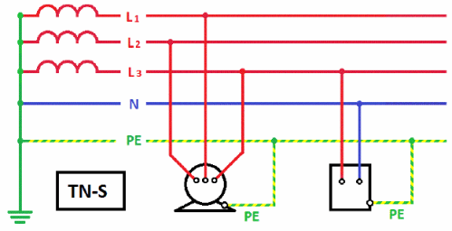
Of course, it is not rational to reconstruct each substation to create a TN-S system, but it is necessary to use safe and reliable systems. Here a compromise appeared - grounding according to the TN-C-S scheme, that is, the "arithmetic average" between the two systems mentioned above. Such a grounding system is used in the overhaul of buildings or the reconstruction of their networks. A four-core cable is connected from the substation to the building and in the building's input shield - the ASU (input switchgear) the PEN conductor is divided into PE and N, and the PEN conductor separation scheme is followed:
- PEN on the cable side are connected to the main ground bus (GZSH) PE, which is electrically connected to the cabinet or switchboard body.
- The GZSH is connected to the zero working bus N, mounted on insulators. These two tires are interconnected by a jumper of the same section as the tires themselves.
- PE conductors are connected to the PE bus, going to sockets and electrical receivers, to the N bus - working zeros of sockets and electrical receivers.
Often there are questions about the place of separation of the PEN conductor. The separation of the PEN-conductor is carried out before the input device into the building or country house, that is, before the input machine or knife switch. The N conductor coming from the N bus is connected to the electricity meter. Separately, I would like to note that after the separation of PEN in the direction from the energy source to the power receiver, the reconnection of PE and N is unacceptable, as is the use of fuses or circuit breakers in PEN, PE and N-conductors.

If you have a TN-C, TN-S system or combinations thereof recommended apply re-grounding (mainly consisting of natural grounding conductors) of PE- and PEN-conductors at the entrance to buildings. And, of course, no matter how perfect the grounding system is, if the resistance of the grounding device (GD) is not checked, there is no guarantee that this system will function properly. Resistance measurement can be carried out by specialists of our laboratory of electrophysical measurements.