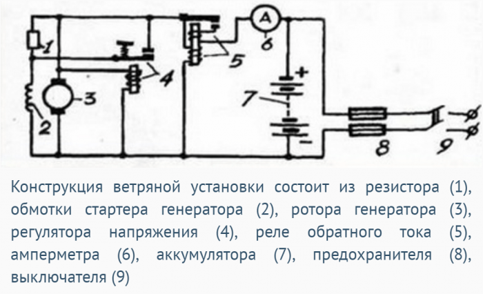
Electricity prices are steadily rising. To make your life comfortable both in hot summer and frosty winter, you should either spend a lot of money on electricity, or look for alternative source energy. In developed countries, solar energy, water and wind have long been used. This is a natural source of nutrition for which you do not have to pay. A fairly popular way to get energy is a windmill that uses wind to generate electricity - a wind generator.
Russia is a rather large country with flat territories. Despite the fact that in many places there are predominantly slow winds, there are regions that are strongly blown by powerful air currents. So why not use this advantage in the economy? All that is required is to spend time and money to make a homemade wind generator. The windmill will fully pay for itself in just a few months. We will consider 2 types of wind turbines that you can do with your own hands.
Rotary wind generator
To begin with, we will consider how to make a simple design of a rotary generator. It's easier to start with a simple one, and you will understand the principle of work. This type of wind generator is suitable for owners of a small garden house. It will not work to use the made windmill for a large cottage, due to the low power of the wind generator.

But the windmill is easy to handle in order to provide light in the evening utility rooms, illuminate the garden path, porch, etc. Let's take a closer look at how to make such a wind turbine with your own hands.
Advantages and disadvantages of a rotary wind generator
When the wind generator is done properly, it will function without any errors. With a 75A battery and a good 1000 W inverter, the windmill will easily provide light to the street, the site of the house, feed the security alarm, video surveillance, etc.

Wind generators of this type have the following advantages:
- ease of installation;
- low cost;
- profitability;
- susceptibility to repair;
- not picky about the operating conditions;
- reliability and quiet operation.
There are several disadvantages of a wind generator:
- low performance of the wind generator;
- complete dependence of the windmill on the wind;
- blades can disrupt the airflow.
Preparation of materials for the wind turbine
The first step is to collect all consumables and parts for the windmill. The wind generator you made will produce a power of no more than 1.5 kW. To make an aggregate you need to have:
- 12 V car alternator.
- Gel or acid battery 12 V.
- Special converter from 12V to 220V and from 700W to 1500W.
- A large stainless steel or aluminum container: a bucket or pan.
- Simple voltmeter.
- Bolts, washers and nuts.
- Relay for charging the battery from the car and charge indicator light.
- Wires with different section(2.5 mm 2 and 4 mm 2).
- Clamps fixing the wind generator.
- Switch "button" semi-hermetic, 12 V.

Also, stock up on these tools:
- grinder or scissors for metal;
- tape measure;
- construction pencil or marker;
- screwdriver, drill, nippers and drill.
Wind generator design work
The work consists in the manufacture of the rotor and the alteration of the generator pulley. The steps are:
- Prepare a bucket or pot.
- Using a tape measure and a marker, make a markup by dividing the container into 4 identical parts.
- Now you need to cut the blades.

Note! Working with scissors for metal, it is necessary to cut a hole under them. If the bucket is not made of painted tin or galvanized steel, then you can use a grinder.
- From the bottom of the bucket and in the pulley, mark the place where the holes will be. Bolts are screwed into them. Take your time, do everything smoothly, as an imbalance may occur during rotation. Then make holes.
- Now bend the blades. Just remember to take into account which direction the generator is spinning.
- The angle of the blade bend affects the area that the wind will meet. This directly affects the speed and speed of the windmill.
- Using bolts, secure the bucket to the pulley.
- Install your wind turbine on the mast, securing it with clamps.
- It remains to connect the wires and assemble the circuit.
- Fix the wires on the mast so that they do not hang out.
To connect the battery, take wires with a cross section of 4 mm 2. The recommended size is no more than 1 m. And thanks to wires with 2.5 mm 2, connect the light and appliances. Don't forget to install an inverter (converter). Connect the device to the network to contacts No. 7 and No. 8 shown in the diagram below. Use wires 4 mm 2 .
That's it, now your wind turbine is ready to go. It can not but rejoice that it is made by hand.

Axial magnetic wind generator
At the heart of such a 220v windmill is a hub from a passenger car with brake discs. If the part is not new, disassemble it, check and lubricate the bearings, and clean off the rust.

Distribute and fix magnets
First you need to stick the magnets on the rotor disk. In this case, the magnets used are not ordinary, but special neodymium magnets. They are much more powerful. You will need 20 magnets, the size of which is 25 by 8 mm. Magnets are placed with alternating poles. For correct location make a template as shown in the photo below.

Advice! If possible, use not round magnets for the wind generator, but rectangular ones. Their magnetic field is concentrated not in the center, but along the length.
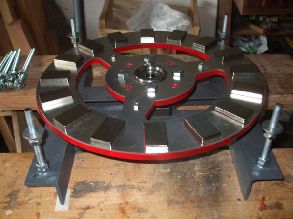
To fix the magnets on the disc, use silicate glue. And for strength at the end, you can fill the magnets with epoxy. To prevent the resin from leaking, make plasticine borders or wrap the disc with tape.
Note! In order not to confuse where the magnet has which pole, you can mark them with “+” or “-”. To determine this - bring one magnet to another. The surfaces of the magnet that are attracted have a "+". If the magnet is repelled, it has a "-" pole.

Three-phase and single-phase generator for wind turbine
If we compare them, then a single-phase device is worse, because under load it vibrates due to the difference in current amplitude. And it appears due to the inconsistency of the current. In three-phase products, this effect is absent. Their power is always the same. The thing is that one phase compensates for the other and vice versa, if the current disappears in one phase, then in the other it will increase.

What is the result? And the fact that three-phase generators have a return of 50% more than single-phase ones. In addition, the absence of vibration, which can irritate and affect comfort, pleases. When working under heavy load, the stator will not hum. If noise does not bother you, and you decide to use a single-phase generator, be prepared for the fact that vibration will adversely affect the operation of the wind generator. Its service life will be shorter.
We wind the coils
It is impossible to call a very high-speed wind generator. It is required to do everything so that the 12 V battery is infected from 100–140 rpm. With these initial data, the total number of turns in the coils should be 1000-1200. But how do you know how many turns per coil? It's simple: this figure is divided by the number of coils.

If you want the wind generator to produce more power at low speeds, you need to make more poles. In this case, the frequency of the current oscillation in the coil will increase. To reduce resistance and increase current resistance, we recommend winding thick wire around the coils. Keep in mind that with a strong voltage, the resistance of the winding can "eat" the current.
Please note that the number and thickness of the magnets that are attached to the disks determine the operating parameters of the generator. To find out how much power a wind generator can produce, wind one coil and spin the generator. Measure the voltage at some RPM without load. For example, for 200 rpm you got a current of 30 V with a resistance of 3 ohms. Subtract from these 30V 12V (battery voltage). Now divide the number you get by 3 ohms. Everything looks like this:
As a result, it turned out 6 A. It is they who will go to the battery. It is clear that in practice it will be slightly less due to losses in the wires.

Coils better make an elongated shape. Then the copper in the sector will come out more, and the turns will be straight. The diameter of the hole inside the coil should be equal to or slightly larger than the size of the magnets.
Note! The thickness of the stator must be the same as the thickness of the magnets.
The shape for the stator can be plywood. But sectors for coils can also be placed on paper by making a plasticine border. The coils must be fixed so that they do not move, and bring the ends of the phases out. Connect all wires with a star or a delta. It remains to test the wind generator by rotating it by hand.

We make a screw and a mast for a wind generator
The mast for the verogenerator must be high, from 8 to 12 m. The base must be concreted. It is better to make the fastening so that the pipe can be easily raised and lowered with a winch. A wind turbine screw will be attached to the pipe from above.

You can make it from plastic pipeØ160 mm. From it cut a screw with six blades, 2 m long.
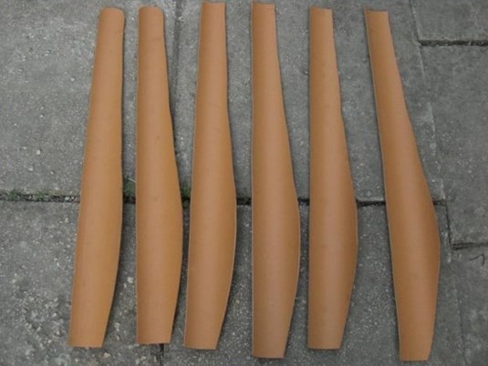
To take the propeller away from a strong gust of wind, make a folding tail. As a result, all the energy generated by the wind generator can be stored in the battery.
That's all, you know how to make a wind turbine with magnets. Now you can use the electricity generated by such a wind generator, saving your money. All your efforts will be rewarded.
Conclusion
From this article, you learned how to make a wind generator with your own hands, and not one, but two types. It is these wind turbines that are loved and used for country houses owners. As you can see, each wind generator is good in something of its own and it is not difficult to make it.
If you live in an area with strong winds, you will see how much lower your electricity bills are thanks to a wind turbine. Such a windmill in the household will never be superfluous. Additionally, we suggest you watch a video on how to make such a wind generator.
Russia has a dual position regarding wind energy resources. On the one hand, due to the vast total area and the abundance of flat areas, the wind is generally plentiful and mostly even. On the other hand, our winds are predominantly low-potential, slow, see fig. On the third, in sparsely populated areas, the winds are violent. Based on this, the task of starting a wind generator on the farm is quite relevant. But, in order to decide whether to buy a fairly expensive device, or make it yourself, you need to think carefully about which type (and there are a lot of them) for what purpose to choose.

Basic concepts
- KIEV - wind energy utilization factor. If a mechanistic flat wind model is used for calculation (see below), it is equal to the efficiency of the rotor of a wind power plant (APU).
- Efficiency - end-to-end efficiency of the APU, from the oncoming wind to the terminals of the electric generator, or to the amount of water pumped into the tank.
- The minimum operating wind speed (MPS) is its speed at which the windmill begins to give current to the load.
- The maximum allowable wind speed (MPS) is its speed at which energy production stops: the automation either turns off the generator, or puts the rotor in a weather vane, or folds it and hides it, or the rotor stops itself, or the APU simply collapses.
- Starting wind speed (CWS) - at this speed, the rotor is able to turn without load, spin up and enter the operating mode, after which the generator can be turned on.
- Negative starting speed (OSS) - this means that the APU (or wind turbine - wind power plant, or WEA, wind power plant) requires mandatory spin-up from an external energy source to start at any wind speed.
- Starting (initial) moment - the ability of the rotor, forcibly slowed down in the air flow, to create a torque on the shaft.
- Wind turbine (VD) - part of the APU from the rotor to the shaft of the generator or pump, or other energy consumer.
- Rotary wind generator - APU, in which wind energy is converted into torque on the power take-off shaft by rotating the rotor in the air flow.
- The operating speed range of the rotor is the difference between MDS and MRS when operating at rated load.
- Slow-speed windmill - in it the linear speed of the parts of the rotor in the flow does not significantly exceed the wind speed or below it. The dynamic head of the flow is directly converted into blade thrust.
- High-speed windmill - the linear speed of the blades is significantly (up to 20 or more times) higher than the wind speed, and the rotor forms its own air circulation. The cycle of converting flow energy into thrust is complex.
Notes:
- Low-speed APUs, as a rule, have lower CIEV than high-speed ones, but they have a starting torque sufficient to spin up the generator without disconnecting the load and zero TCO, i.e. absolutely self-starting and applicable in the lightest winds.
- Slowness and speed are relative concepts. A household windmill at 300 rpm can be low-speed, and powerful APUs of the EuroWind type, from which the fields of wind farms, wind farms (see. Fig.) Are gaining and the rotors of which make about 10 rpm - high-speed, because. with such a diameter, the linear speed of the blades and their aerodynamics over most of the span are quite “airplane”, see below.
What generator is needed?
An electric generator for a domestic windmill must generate electricity in a wide range of rotational speeds and have the ability to self-start without automation and external power sources. In the case of using an APU with OSS (windmills with spin-up), which, as a rule, have high KIEV and efficiency, it must also be reversible, i.e. be able to work as an engine. At powers up to 5 kW, this condition is satisfied by electric machines with permanent magnets based on niobium (supermagnets); on steel or ferrite magnets, you can count on no more than 0.5-0.7 kW.
Note: asynchronous alternators or collector alternators with a non-magnetized stator are not suitable at all. With a decrease in wind strength, they will “go out” long before its speed drops to MRS, and then they will not start themselves.
An excellent "heart" of the APU with a power of 0.3 to 1-2 kW is obtained from an alternator with a built-in rectifier; most of them are now. Firstly, they keep the output voltage of 11.6-14.7 V in a fairly wide range of speeds without external electronic stabilizers. Secondly, the silicon gates open when the voltage on the winding reaches about 1.4 V, and before that the generator "does not see" the load. To do this, the generator must already be quite well untwisted.
In most cases, the oscillator can be connected directly, without gear or belt drive, to the high-speed HP shaft by selecting the speed by choosing the number of blades, see below. "Fast-walkers" have a small or zero starting torque, but the rotor, even without disconnecting the load, will have enough time to spin up before the valves open and the generator gives current.
Choice in the wind
Before deciding which wind generator to make, let's decide on the local aerology. in grey-greenish(windless) areas of the wind map, at least some sense will be only from a sailing wind turbine(and we'll talk about them later). If you need a constant power supply, then you will have to add a booster (rectifier with voltage stabilizer), charger, powerful battery, inverter 12/24/36/48 VDC to 220/380 VAC 50 Hz. Such an economy will cost no less than $20,000, and it is unlikely that it will be possible to remove a long-term power of more than 3-4 kW. In general, with a relentless pursuit of alternative energy better to look for another source.
In yellow-green, slightly windy places, if you need electricity up to 2-3 kW, you can take on a low-speed vertical wind generator yourself. They have been developed innumerable, and there are designs that, in terms of KIEV and efficiency, are almost not inferior to industrial-made “blades”.
If you are going to buy a wind turbine for your home, then it is better to focus on a windmill with a sailing rotor. There are many disputes, and in theory not everything is clear yet, but they work. In the Russian Federation, "sailboats" are produced in Taganrog with a capacity of 1-100 kW.
In red, windy, regions, the choice depends on the required power. In the range of 0.5-1.5 kW, self-made "verticals" are justified; 1.5-5 kW - purchased "sailboats". "Vertical" can also be purchased, but it will cost more than the APU of the horizontal scheme. And, finally, if you need a windmill with a power of 5 kW or more, then you need to choose between horizontal purchased “blades” or “sailboats”.
Note: many manufacturers, especially the second tier, offer kits of parts from which you can assemble a wind generator with a power of up to 10 kW on your own. Such a set will cost 20-50% cheaper than a ready-made one with installation. But before buying, you need to carefully study the aerology of the intended installation site, and then select the appropriate type and model according to the specifications.
About security
Parts of a wind turbine for domestic use in operation can have a linear speed exceeding 120 and even 150 m / s, and a piece of any solid material weighing 20 g, flying at a speed of 100 m / s, with a “successful” hit, kills a healthy man on the spot. A steel or hard plastic plate 2 mm thick, moving at a speed of 20 m/s, cuts it in half.
In addition, most windmills over 100 watts are quite noisy. Many generate ultra-low (less than 16 Hz) frequency air pressure fluctuations - infrasounds. Infrasounds are inaudible, but detrimental to health, and spread very far.
Note: in the late 80s, there was a scandal in the United States - the largest wind farm in the country at that time had to be closed. The Indians from the reservation, 200 km from the field of her APU, proved in court that the health disorders that sharply increased in them after the commissioning of the wind farm were due to its infrasounds.
For the above reasons, the installation of the APU is allowed at a distance of at least 5 of their heights from the nearest residential buildings. In the yards of private households, it is possible to install windmills of industrial production, appropriately certified. It is generally impossible to install APUs on roofs - during their operation, even for low-power ones, there are alternating mechanical loads that can cause resonance building structure and its destruction.
Note: the height of the APU is the highest point of the swept disk (for bladed rotors) or geometric figure (for vertical APUs with a rotor on the pole). If the APU mast or the rotor axis protrude even higher, the height is calculated according to their top - the top.
Wind, aerodynamics, KIEV
A home-made wind generator obeys the same laws of nature as a factory-made one calculated on a computer. And the do-it-yourselfer needs to understand the basics of his work very well - most often he does not have expensive ultra-modern materials and technological equipment at his disposal. The aerodynamics of the APU is oh so difficult ...
Wind and KIEV
To calculate serial factory APUs, the so-called. flat mechanistic wind model. It is based on the following assumptions:
- Wind speed and direction are constant within the effective rotor surface.
- Air is a continuous medium.
- The effective surface of the rotor is equal to the swept area.
- The energy of the air flow is purely kinetic.
Under such conditions, the maximum energy of a unit volume of air is calculated according to the school formula, assuming the air density under normal conditions is 1.29 kg * cu. m. At a wind speed of 10 m / s, one cube of air carries 65 J, and from one square of the effective surface of the rotor, it is possible, at 100% efficiency of the entire APU, to remove 650 W. This is a very simplistic approach - everyone knows that the wind is not perfectly even. But this has to be done in order to ensure the repeatability of products - a common thing in technology.
The flat model should not be ignored, it gives a clear minimum of available wind energy. But air, firstly, is compressible, and secondly, it is very fluid (dynamic viscosity is only 17.2 μPa * s). This means that the flow can flow around the swept area, reducing the effective surface and KIEV, which is most often observed. But in principle, the reverse situation is also possible: the wind flows to the rotor and the area of the effective surface then turns out to be greater than the swept one, and KIEV is greater than 1 relative to that for a flat wind.
Let's give two examples. The first is a pleasure yacht, rather heavy, the yacht can go not only against the wind, but also faster than it. The wind is meant external; the apparent wind must still be faster, otherwise how will it pull the ship?
The second is a classic of aviation history. On tests of the MIG-19, it turned out that the interceptor, which was a ton heavier than a front-line fighter, accelerates faster in speed. With the same engines in the same airframe.
Theorists did not know what to think, and seriously doubted the law of conservation of energy. In the end, it turned out that the point was the cone of the radar fairing protruding from the air intake. From its toe to the shell, an air seal appeared, as if raking it from the sides to the engine compressors. Since then, shock waves have become firmly established in theory as useful, and the fantastic flight performance of modern aircraft is due in no small measure to their skillful use.
Aerodynamics
The development of aerodynamics is usually divided into two eras - before N. G. Zhukovsky and after. His report "On attached vortices" dated November 15, 1905 marked the beginning of a new era in aviation.
Before Zhukovsky, they flew on flat sails: it was believed that the particles of the oncoming flow give all their momentum to the leading edge of the wing. This made it possible to immediately get rid of the vector quantity - the moment of momentum - which generated furious and most often non-analytical mathematics, go to much more convenient scalar purely energy relations, and eventually get the calculated pressure field on the carrier plane, more or less similar to the present one.
Such a mechanistic approach made it possible to create devices that could, at the very least, take to the air and fly from one place to another, without necessarily crashing to the ground somewhere along the way. But the desire to increase speed, carrying capacity and other flight qualities more and more revealed the imperfection of the original aerodynamic theory.
Zhukovsky's idea was as follows: air passes a different path along the upper and lower surfaces of the wing. From the condition of medium continuity (vacuum bubbles do not form in the air by themselves), it follows that the velocities of the upper and lower flows descending from the trailing edge must differ. Due to the albeit small, but finite viscosity of the air, a vortex should form there due to the difference in speeds.
The vortex rotates, and the law of conservation of momentum, as immutable as the law of conservation of energy, is also valid for vector quantities, i.e. must take into account the direction of movement. Therefore, immediately, on the trailing edge, an oppositely rotating vortex with the same torque should form. For what? Due to the energy generated by the engine.
For the practice of aviation, this meant a revolution: by choosing the appropriate wing profile, it was possible to launch an attached vortex around the wing in the form of a circulation Г, increasing its lift. That is, by spending a part, and for high speeds and wing loads - a large part, of the engine power, you can create an air flow around the device, which allows you to achieve better flight qualities.
This made aviation aviation, and not a part of aeronautics: now the aircraft could create the environment necessary for the flight and no longer be a toy of air currents. All you need is a more powerful engine, and more and more powerful ...
Again KIEV
But the windmill does not have a motor. He, on the contrary, must take energy from the wind and give it to consumers. And here it comes out - he pulled out his legs, his tail got stuck. They let too little wind energy into the rotor's own circulation - it will be weak, the blade thrust will be small, and KIEV and power will be low. Let's give a lot for circulation - the rotor will spin like crazy at idle in a light wind, but consumers again get a little: they gave a little load, the rotor slowed down, the wind blew off the circulation, and the rotor stopped.
Law of energy conservation " golden mean” gives just in the middle: we give 50% of the energy to the load, and for the remaining 50% we twist the flow to the optimum. Practice confirms the assumptions: if the efficiency of a good pulling propeller is 75-80%, then the KIEV of a bladed rotor that is also carefully calculated and blown in a wind tunnel reaches 38-40%, i.e. up to half of what can be achieved with an excess of energy.
Modernity
Today, aerodynamics, armed with modern mathematics and computers, is increasingly moving away from inevitably simplifying models to an accurate description of the behavior of a real body in a real flow. And here, in addition to the general line - power, power, and once again power! – side ways are discovered, but promising just with a limited amount of energy entering the system.
The famous alternative aviator Paul McCready created an airplane back in the 80s, with two motors from a 16 hp chainsaw. showing 360 km / h. Moreover, its chassis was a tricycle non-retractable, and the wheels were without fairings. None of McCready's machines went on line and did not stand on combat duty, but two - one with piston engines and propellers, and the other jet - for the first time in history circled the globe without landing on one gas station.
The sails that gave rise to the original wing were also significantly affected by the development of the theory. "Live" aerodynamics allowed the yachts with a wind of 8 knots. stand on hydrofoils (see fig.); to disperse such a hulk to the desired speed with a propeller, an engine of at least 100 hp is required. Racing catamarans with the same wind go at a speed of about 30 knots. (55 km/h).
There are also finds that are completely non-trivial. Fans of the rarest and most extreme sport - base jumping - wearing an apecial wing suit, wingsuit, fly without a motor, maneuvering at a speed of more than 200 km / h (fig. on the right), and then land smoothly in a pre-selected place. In which fairy tale do people fly by themselves?
Many mysteries of nature have also been solved; in particular, the flight of a beetle. According to classical aerodynamics, it is not capable of flying. Just like the ancestor of the "stealth" F-117 with its diamond-shaped wing, it is also not able to take to the air. And the MIG-29 and Su-27, which can fly tail first for some time, do not fit into any ideas at all.
And why, then, when dealing with wind turbines, not a fun and not a tool for the destruction of their own kind, but a source of a vital resource, it is imperative to dance from the theory of weak flows with its model of a flat wind? Is there really no way to go further?
What to expect from a classic?
However, the classics should not be abandoned in any case. It provides a foundation without leaning on which one cannot rise higher. Just as set theory does not cancel the multiplication table, and quantum chromodynamics does not make apples fly up from trees.
So, what can you expect from the classical approach? Let's look at the picture. Left - types of rotors; they are depicted conditionally. 1 - vertical carousel, 2 - vertical orthogonal ( wind turbine); 2-5 - bladed rotors with different amount blades with optimized profiles.
On the right, the horizontal axis is plotted relative speed rotor, i.e., the ratio of the linear speed of the blade to the wind speed. Vertically up - KIEV. And down - again, the relative torque. A single (100%) torque is considered to be one that creates a rotor forcibly decelerated in the flow with 100% KIEV, i.e. when all the energy of the flow is converted into rotational force.
This approach allows us to draw far-reaching conclusions. For example, the number of blades must be chosen not only and not so much according to the desired rotation speed: 3- and 4-blades immediately lose a lot in terms of KIEV and torque compared to 2- and 6-blades that work well in approximately the same speed range. And outwardly similar carousel and orthogonal have fundamentally different properties.
In general, preference should be given to bladed rotors, except in cases where extreme cheapness, simplicity, maintenance-free self-starting without automation are required, and it is impossible to climb the mast.
Note: we’ll talk about sailing rotors in particular - they don’t seem to fit into the classics.
Vertical lines
APUs with a vertical axis of rotation have an undeniable advantage for everyday life: their components that require maintenance are concentrated at the bottom and there is no need to lift them up. There remains, and even then not always, a self-aligning thrust bearing, but it is strong and durable. Therefore, when designing a simple wind generator, the selection of options must begin with verticals. Their main types are shown in fig.
sun
In the first position - the simplest, most often called the Savonius rotor. In fact, it was invented in 1924 in the USSR by Ya. A. and A. A. Voronin, and the Finnish industrialist Sigurd Savonius shamelessly appropriated the invention, ignoring the Soviet copyright certificate, and began mass production. But the introduction of the invention in the fate means a lot, so we, in order not to stir up the past and not to disturb the ashes of the dead, we will call this windmill the Voronin-Savonius rotor, or for short, the Sun.
VS for a do-it-yourselfer is good for everyone, except for the "locomotive" KIEV in 10-18%. However, in the USSR a lot of work was done on it, and there are developments. Below we will consider an improved design, not much more complicated, but according to KIEV, it gives odds to the blades.
Note: a two-blade BC does not spin, but jerks; The 4-blade is only slightly smoother, but loses a lot in KIEV. To improve 4-"trough" most often spread over two floors - a pair of blades below, and another pair, rotated 90 degrees horizontally, above them. KIEV is preserved, and side loads on the mechanics weaken, but the bending ones increase somewhat, and with a wind of more than 25 m / s, such an APU has a shaft, i.e. without a bearing stretched by the guys above the rotor, “breaks the tower”.
Daria
The next one is the Daria rotor; KIEV - up to 20%. It is even simpler: the blades are made of a simple elastic band without any profile. The theory of the Darrieus rotor is not well developed yet. It is only clear that it begins to unwind due to the difference in the aerodynamic resistance of the hump and the belt pocket, and then it becomes like a high-speed one, forming its own circulation.
The torque is small, and in the starting positions of the rotor parallel and perpendicular to the wind, there is no such thing at all, so self-promotion is possible only with an odd number of blades (wings?).
The Darrieus rotor has two more bad qualities. First, during rotation, the thrust vector of the blade describes a complete revolution relative to its aerodynamic focus, and not smoothly, but jerkily. Therefore, the Darrieus rotor quickly breaks its mechanics even with a flat wind.
Secondly, Daria not only makes noise, but yells and squeals, to the point that the tape is torn. This is due to its vibration. And the more blades, the stronger the roar. So Daria, if they do, then two-blade, from expensive high-strength sound-absorbing materials(carbon fiber, mylar), and for promotion in the middle of the mast-pole, a small aircraft is fitted.
orthogonal
At pos. 3 - orthogonal vertical rotor with profiled blades. Orthogonal because the wings stick out vertically. The transition from the BC to the orthogonal is illustrated in Fig. left.
The angle of installation of the blades relative to the tangent to the circle, touching the aerodynamic foci of the wings, can be either positive (in the figure) or negative, according to the strength of the wind. Sometimes the blades are made swivel and windcocks are placed on them, automatically holding the alpha, but such structures often break.
The central body (blue in the figure) allows you to bring the KIEV to almost 50%. In a three-bladed orthogonal, it should have the shape of a triangle in the section with slightly convex sides and rounded corners, and with a larger number of blades, a simple cylinder is sufficient. But the theory for the orthogonal optimal amount blades gives unambiguously: there should be exactly 3 of them.
Orthogonal refers to high-speed windmills with OSS, i.e. necessarily requires promotion during commissioning and after calm. According to the orthogonal scheme, serial maintenance-free APUs with a power of up to 20 kW are produced.
Helicoid
Helicoid rotor, or Gorlov rotor (pos. 4) - a kind of orthogonal that provides uniform rotation; an orthogonal with straight wings "tears" only slightly weaker than a two-bladed aircraft. The bending of the blades along the helicoid avoids the loss of KIEV due to their curvature. Although the curved blade rejects part of the flow without using it, it also rakes a part into the zone of the highest linear speed, compensating for losses. Helicoids are used less often than other windmills, because. due to the complexity of manufacturing, they turn out to be more expensive than counterparts of equal quality.
Barrel-barrel
For 5 pos. – BC type rotor surrounded by a guide vane; its scheme is shown in fig. on right. Rarely found in industrial design, tk. expensive land acquisition does not compensate for the increase in capacity, and the material consumption and complexity of production are high. But a do-it-yourselfer who is afraid of work is no longer a master, but a consumer, and if no more than 0.5-1.5 kW is needed, then for him a “barrel-barrel” is a tidbit:
- This type of rotor is absolutely safe, silent, does not create vibrations and can be installed anywhere, even on a playground.
- Bend the "trough" of galvanized and weld the frame of the pipes - the work is nonsense.
- Rotation is absolutely uniform, mechanical parts can be taken from the cheapest or from the trash.
- Not afraid of hurricanes - too strong wind cannot push into the "barrel"; a streamlined vortex cocoon appears around it (we will still encounter this effect).
- And most importantly, since the surface of the “grab” is several times larger than that of the rotor inside, KIEV can be super-unit, and the torque at 3 m / s at a “barrel” of three meters in diameter is such that a 1 kW generator with a maximum load, as It is said that it is better not to twitch.
Video: Lenz wind generator
In the 60s in the USSR, E. S. Biryukov patented a carousel APU with KIEV 46%. A little later, V. Blinov achieved 58% from the design on the same principle of KIEV, but there is no data on its tests. And full-scale tests of Biryukov’s Armed Forces were carried out by the staff of the Inventor and Rationalizer magazine. A two-story rotor with a diameter of 0.75 m and a height of 2 m, with a fresh wind, spun a 1.2 kW asynchronous generator at full power and withstood 30 m/s without breakage. Drawings of the APU Biryukov are shown in fig.
- roof galvanized rotor;
- self-aligning double row ball bearing;
- shrouds - 5 mm steel cable;
- axle shaft - steel pipe with a wall thickness of 1.5-2.5 mm;
- aerodynamic speed control levers;
- speed control blades - 3-4 mm plywood or sheet plastic;
- speed control rods;
- speed controller load, its weight determines the speed;
- drive pulley - a bicycle wheel without a tire with a chamber;
- thrust bearing - thrust bearing;
- driven pulley - regular generator pulley;
- generator.
Biryukov received several copyright certificates for his APU. First, pay attention to the section of the rotor. When accelerating, it works like a sun, creating a large starting torque. As it spins, a vortex cushion is created in the outer pockets of the blades. From the wind's point of view, the blades become profiled and the rotor turns into a high-speed orthogonal, with the virtual profile changing according to the strength of the wind.
Secondly, the profiled channel between the blades in the operating speed range works as a central body. If the wind increases, then a vortex cushion is also created in it, which goes beyond the rotor. There is the same vortex cocoon as around the APU with a guide vane. The energy for its creation is taken from the wind, and it is no longer enough to break the windmill.
Thirdly, the speed controller is designed primarily for the turbine. He keeps her speed optimal from the point of view of KIEV. And the optimum frequency of rotation of the generator is provided by the choice of the gear ratio of the mechanics.
Note: after publications in the IR for 1965, Biryukov's Armed Forces disappeared into oblivion. The author did not wait for a response from authorities. The fate of many Soviet inventions. They say that some Japanese became a billionaire by regularly reading Soviet popular technical magazines and patenting everything worthy of attention.
Lopatniki
As u said, according to the classics, a horizontal wind turbine with a bladed rotor is the best. But, firstly, he needs a stable, at least medium-strength wind. Secondly, the design for a do-it-yourselfer is fraught with a lot of pitfalls, which is why often the fruit of long hard work illuminates the toilet, hallway or porch at best, or even turns out to be only able to unwind itself.
According to the diagrams in Fig. consider in more detail; positions:
- Fig. BUT:
- rotor blades;
- generator;
- generator frame;
- protective weather vane (hurricane shovel);
- current collector;
- chassis;
- rotary node;
- working weather vane;
- mast;
- clamp for shrouds.
- Fig. B, top view:
- protective weather vane;
- working weather vane;
- protective wind vane spring tension regulator.
- Fig. G, current collector:
- collector with copper continuous ring tires;
- spring-loaded copper-graphite brushes.
Note: hurricane protection for a horizontal blade with a diameter of more than 1 m is absolutely necessary, because. he is not capable of creating a vortex cocoon around himself. With smaller sizes it is possible to achieve a rotor endurance of up to 30 m/s with propylene blades.
So, where are we waiting for "stumbling"?
blades
To expect to achieve power on the generator shaft of more than 150-200 W on blades of any span, cut out of a thick-walled plastic pipe, as is often advised, is the hope of a hopeless amateur. A blade from a pipe (unless it is so thick that it is used simply as a blank) will have a segmental profile, i.e. its top, or both surfaces will be arcs of a circle.
Segment profiles are suitable for incompressible media, such as hydrofoils or propeller blades. For gases, a blade of variable profile and pitch is needed, for an example, see Fig .; span - 2 m. This will be a complex and time-consuming product that requires painstaking calculations in full theory, blowing in the pipe and field tests.
Generator
When the rotor is mounted directly on its shaft, the standard bearing will soon break - there is no equal load on all the blades in windmills. We need an intermediate shaft with a special support bearing and a mechanical transmission from it to the generator. For large windmills, a self-aligning double-row bearing is taken; in best models- three-tier, Fig. D in fig. above. This allows the rotor shaft to not only bend slightly, but also move slightly from side to side or up and down.
Note: It took about 30 years to develop a thrust bearing for the EuroWind type APU.
emergency weather vane
The principle of its operation is shown in Fig. B. The wind, intensifying, presses on the shovel, the spring stretches, the rotor warps, its speed drops and in the end it becomes parallel to the flow. Everything seems to be fine, but - it was smooth on paper ...
On a windy day, try to hold the lid of boiled water or a large pot by the handle parallel to the wind. Just be careful - the fidgety piece of iron can hit the physiognomy so that it breaks the nose, cuts the lip, and even knocks out the eye.
Flat wind occurs only in theoretical calculations and, with sufficient accuracy for practice, in wind tunnels. In reality, a hurricane windmills with a hurricane shovel distorts more than completely defenseless ones. Still, it's better to change warped blades than to do everything all over again. AT industrial plants- another thing. There, the pitch of the blades, for each individually, monitors and regulates automation under the control of the on-board computer. And they are made from heavy-duty composites, not from water pipes.
current collector
This is a regularly serviced node. Any power engineer knows that the collector with brushes needs to be cleaned, lubricated, adjusted. And the mast is from a water pipe. You won’t climb in, once a month or two you will have to throw the whole windmill to the ground and then raise it again. How long will he last from such "prevention"?
Video: bladed wind generator + solar panel for power supply to the dacha
Mini and micro
But as the size of the blade decreases, the difficulty decreases with the square of the wheel diameter. It is already possible to manufacture a horizontal bladed APU on its own for a power of up to 100 W. 6-blade will be optimal. With more blades, the diameter of the rotor, designed for the same power, will be smaller, but it will be difficult to firmly fix them on the hub. Rotors with less than 6 blades can be ignored: a 2-blade 100 W needs a rotor with a diameter of 6.34 m, and a 4-blade of the same power needs 4.5 m. For a 6-blade, the power-diameter relationship is expressed as follows :
- 10 W - 1.16 m.
- 20 W - 1.64 m.
- 30 W - 2 m.
- 40 W - 2.32 m.
- 50 W - 2.6 m.
- 60 W - 2.84 m.
- 70 W - 3.08 m.
- 80 W - 3.28 m.
- 90 W - 3.48 m.
- 100 W - 3.68 m.
- 300 W - 6.34 m.
It will be optimal to count on a power of 10-20 watts. Firstly, a plastic blade with a span of more than 0.8 m will not withstand winds of more than 20 m/s without additional protection measures. Secondly, with a blade span of up to the same 0.8 m, the linear speed of its ends will not exceed the wind speed by more than three times, and the requirements for profiling with twist are reduced by orders of magnitude; here the “trough” with a segmented profile from a pipe will already work quite satisfactorily, pos. B in fig. And 10-20 W will provide power to the tablet, recharge the smartphone or light up the housekeeper light bulb.
Next, choose a generator. A Chinese motor is perfect - a wheel hub for electric bicycles, pos. 1 in fig. Its power as a motor is 200-300 watts, but in generator mode it will give up to about 100 watts. But will it fit us in terms of turnover?
The speed factor z for 6 blades is 3. The formula for calculating the speed of rotation under load is N = v / l * z * 60, where N is the speed of rotation, 1 / min, v is the wind speed, and l is the circumference of the rotor. With a blade span of 0.8 m and a wind of 5 m/s, we get 72 rpm; at 20 m/s - 288 rpm. A bicycle wheel also rotates at about the same speed, so we will remove our 10-20 watts from a generator that can give 100. You can put the rotor directly on its shaft.
But here the following problem arises: having spent a lot of work and money, at least for a motor, we got ... a toy! What is 10-20, well, 50 watts? And a bladed windmill that can power at least a TV set cannot be made at home. Is it possible to buy a ready-made mini-wind generator, and will it not cost less? Still as possible, and even as cheaper, see pos. 4 and 5. In addition, it will also be mobile. Put it on a stump - and use it.
The second option is if somewhere a stepper motor is lying around from an old 5- or 8-inch drive, or from a paper drive or carriage of an unusable inkjet or dot matrix printer. It can work as a generator, and attaching a carousel rotor from cans (pos. 6) to it is easier than assembling a structure like that shown in pos. 3.
In general, according to the “blades”, the conclusion is unambiguous: home-made - rather in order to make one's heart's content, but not for real long-term energy efficiency.
Video: the simplest wind generator for dacha lighting
sailboats
The sailing wind generator has been known for a long time, but the soft panels of its blades (see Fig.) began to be made with the advent of high-strength wear-resistant synthetic fabrics and films. Multi-blade windmills with rigid sails are widely distributed around the world as a drive for low-power automatic pumps, but their technical data is even lower than that of carousels.
However, a soft sail like the wing of a windmill, it seems, was not so simple. It's not about wind resistance (manufacturers do not limit the maximum allowable wind speed): yachtsmen-sailboats already know that it is almost impossible for the wind to break the panel of a Bermuda sail. Rather, the sheet will rip out, or the mast will break, or the whole vessel will make an “overkill turn”. It's about energy.
Unfortunately, exact test data cannot be found. Based on user feedback, it was possible to compile "synthetic" dependences for the Taganrog-made wind turbine VEU-4.380/220.50 with a wind wheel diameter of 5 m, a wind head weight of 160 kg and a rotation speed of up to 40 1/min; they are shown in Fig.
Of course, there can be no guarantees for 100% reliability, but even so it is clear that there is no smell of a flat-mechanistic model here. In no way can a 5-meter wheel in a flat wind of 3 m / s give about 1 kW, at 7 m / s reach a plateau in power and then keep it until a severe storm. Manufacturers, by the way, declare that the nominal 4 kW can be obtained at 3 m / s, but when installed by them according to the results of local aerology studies.
Quantitative theory is also not found; The developers' explanations are unintelligible. However, since people buy Taganrog wind turbines, and they work, it remains to be assumed that the declared conical circulation and propulsion effect are not fiction. In any case, they are possible.
Then, it turns out, BEFORE the rotor, according to the law of conservation of momentum, a conical vortex should also arise, but expanding and slow. And such a funnel will drive the wind to the rotor, its effective surface it will turn out to be more swept, and KIEV - over unity.
Field measurements of the pressure field in front of the rotor, at least with a household aneroid, could shed light on this question. If it turns out to be higher than from the sides to the side, then, indeed, sailing APUs work like a beetle flies.
Homemade generator
From the foregoing, it is clear that it is better for do-it-yourselfers to take on either verticals or sailboats. But both are very slow, and the transfer to a high-speed generator is extra work, extra costs and losses. Is it possible to make an efficient low-speed electric generator yourself?
Yes, you can, on niobium alloy magnets, the so-called. supermagnets. The manufacturing process of the main parts is shown in Fig. Coils - each of 55 turns of 1 mm copper wire in heat-resistant high-strength enamel insulation, PEMM, PETV, etc. The height of the windings is 9 mm.
Notice the keyways in the rotor halves. They should be arranged so that the magnets (they are glued to the magnetic circuit with epoxy or acrylic) after assembly converge with opposite poles. "Pancakes" (magnetic circuits) must be made of a magnetically soft ferromagnet; normal structural steel will do. The thickness of the “pancakes” is at least 6 mm.
It's actually better to buy magnets with an axle hole and tighten them with screws; supermagnets are attracted with terrible force. For the same reason, a cylindrical spacer 12 mm high is put on the shaft between the "pancakes".
The windings that make up the stator sections are connected according to the schemes also shown in fig. The soldered ends should not be stretched, but should form loops, otherwise the epoxy, which will be filled with the stator, can break the wires when it hardens.
The stator is cast in the mold to a thickness of 10 mm. It is not necessary to center and balance, the stator does not rotate. The gap between the rotor and the stator is 1 mm on each side. The stator in the generator housing must be securely fixed not only from displacement along the axis, but also from turning; a strong magnetic field with a current in the load will pull it along.
Video: do-it-yourself windmill generator
Conclusion
And what do we have in the end? The interest in "blades" is explained more by their spectacular appearance than by the actual performance in home-made performance and at low power. A self-made carousel APU will provide “standby” power for charging a car battery or powering a small house.
But with sailing APUs, masters with a creative vein should experiment, especially in a mini version, with a wheel of 1-2 m in diameter. If the developers' assumptions are correct, then it will be possible to remove all of its 200-300 watts from this using the Chinese generator engine described above.
Andrey said:
Thank you for your free consultation ... And the prices “from firms” are not really expensive, and I think that artisans from the outback will be able to make generators like yours. And Li-po batteries can be ordered from China, inverters in Chelyabinsk are very good (with a smooth sine). And sails, blades or rotors are another reason for the flight of thoughts of our handy Russian men.
Ivan said:
question:
For windmills with a vertical axis (position 1) and the “Lenz” option, it is possible to add additional detail- an impeller, exposed to the wind, and covering the useless side from it (going towards the wind). That is, the wind will not slow down the blade, but this “screen”. Setting downwind with a “tail” located behind the windmill itself below and above the blades (ridges). I read the article and an idea was born.By clicking the "Add comment" button, I agree to the site.


Wind is free energy! So let's use it for personal purposes. If the creation of a wind farm in industrial scale this is very expensive, because in addition to the generator, a number of studies and calculations need to be carried out, the state does not bear such expenses, and investors in the countries former USSR- for some reason it does not cause much interest. Then privately you can make a mini-windmill for your own needs. It should be understood that the project of converting your home to alternative energy is a very expensive undertaking.
As already mentioned: you need to make long-term observations and calculations in order to choose the optimal ratio of the sizes of the wind wheel and generator, suitable for your climate, wind rose and average annual wind speed.
The efficiency of a wind power plant within the same region can differ significantly, this is due to the fact that wind movement depends not only on climate zone but also on the terrain.

However, you can find out what wind power is with minimal cost by assembling a budget installation to power a low-power load, such as a smartphone, light bulbs or a radio. With the right approach, you can provide electricity small house or cottage area.

Let's look at how you can make the simplest wind turbine with your own hands.
Low-power windmills from improvised means
The computer cooler is a brushless motor, which in its original form is of no practical value.

It needs to be rewound, since in the original the windings are connected in an inappropriate way. Winding coils alternately:
Clockwise;
Counterclock-wise;
Clockwise;
Counterclock-wise.

You need to connect adjacent coils in series, or even better, wind it with one piece of wire, moving from one groove to another. In this case, choose the thickness of the wire arbitrarily, it would be better if you wind as many turns as possible, and this is possible when using the thinnest wire.
The output voltage from such a generator will be variable, and its value will depend on the speed (wind speed), install a diode bridge from Schottky diodes to straighten it to a constant, ordinary diodes will do, but it will be worse, because. voltage will drop from 1 to 2 volts.
Lyrical digression, a little theory
Remember the value of the EMF is:
where L is the length of the conductor placed in a magnetic field; V is the speed of rotation of the magnetic field;
When upgrading the generator, you can only influence the length of the conductor, that is, the number of turns of each of the coils. The number of turns - determines the output voltage, and the thickness of the wire - the maximum current load.
In practice, it is impossible to influence the wind speed. However, there is also a way out of this situation, if you know the typical wind speed for your area, you can design a suitable screw for a wind turbine, as well as a gearbox or belt drive, to provide sufficient speed to generate the required voltage.
IMPORTANT: Faster does not mean better! If the rotation speed of the wind generator is too high, its resource will be reduced, the lubricating properties of the bushings or bearings of the rotor will deteriorate, and it will jam, and the breakdown of the winding insulation in the generator will most likely occur
The generator consists of:

We increase the power of the generator from a computer cooler
First, the more blades and wheel diameter, the better, so take a closer look at 120mm coolers.
Secondly, we have already said that the voltage also depends on the magnetic field, the fact is that industrial generators high power have excitation windings, and low power - strong magnets. The magnets in the cooler are extremely weak and do not allow you to achieve good results from the generator, and the gap between the rotor and the stator is very large - about 1 mm, and this is with already weak magnets.

The solution to this problem is to radically change the design of the generator. Rather, only an impeller is required from the cooler; a motor from a printer or any other household appliance can be used as a generator. The most common are brushed motors with permanent magnet excitation.
As a result, it will look like this.

The power of such a generator is enough to power the LEDs, the radio. It will not be enough to recharge the phone, the phone will display the charging process, but the current will be extremely small, up to 100 amperes, with a wind of 5-10 meters per second.
Stepper motors as a wind generator
A stepper motor is very often found in computer and household appliances, in various players, floppy drives (old 5.25” models are interesting), printers (especially dot matrix), scanners, etc.
These motors without alterations can work as a generator, they are a rotor with permanent magnets, and a stator with windings, a typical connection diagram of a stepper motor in generator mode is shown in the figure.

The circuit has a 5 volt linear stabilizer, type L7805, which will allow you to safely connect mobile phones to such a windmill to charge them.

The photo shows a generator from a stepper motor with installed blades.
The engine in a particular case with 4 output wires, the diagram is accordingly for it. An engine with such dimensions in generator mode produces approximately 2 W in light wind (wind speed about 3 m / s) and 5 m / s in strong (up to 10 m / s).
By the way, here is a similar circuit with a zener diode, instead of L7805. Allows you to charge Li-ion batteries.

Refinement of a homemade windmill
To make the generator work more efficiently, you need to make a guide shank for it and fix it movably on the mast. Then, when the direction of the wind changes, the direction of the wind generator will change. Then the following problem arises - the cable going from the generator to the consumer will twist around the mast. To solve this, you need to provide a moving contact. A ready-made solution is sold on Ebay and Aliexpress.

The bottom three wires are motionless going down, and the upper bundle of wires is movable, a sliding contact or a brush mechanism is installed inside. If you do not have the opportunity to buy, be smart, and, inspired by the decision of the designers of the Zhiguli car, namely the implementation of the movable contact of the signal button on the steering wheel, and do something similar. Or use the contact pad from the electric kettle.

By connecting the connectors, you get a moving contact.
Powerful wind generator from improvised means.
For more power, you can use two options:
1. Generator from a screwdriver (10-50 W);
You only need a motor from a screwdriver, the option is similar to the previous one, you can use fan blades as a screw, this will increase the final power of your installation.
Here is an example of such a project:

Pay attention to how a gear overdrive is implemented here - the wind generator shaft is located in a pipe, at its end there is a gear that transmits rotation to a smaller gear mounted on the motor shaft. An increase in engine speed also occurs in industrial wind turbines. Reducers are used everywhere.

However, in a homemade environment, making a gearbox becomes a big problem. You can remove the gearbox from the power tool, it is needed there to reduce the high speed on the shaft of the collector motor to the normal speed of the chuck on the drill, or the grinder disk:
The drill has a planetary gearbox;
Installed in the grinder angle gearbox(will be useful for the installation of some installations and reduce the load from the wind turbine tail);
Gearbox from a hand drill.

This version of a homemade wind generator can already charge 12 V batteries, but a converter is needed to generate the charging current and voltage. This task can be simplified by using a car generator.

The advantage of such a generator is the ability to use it to charge car batteries, in principle, it is intended for this. Autogenerators have a built-in voltage regulator relay, which eliminates the need to buy additional stabilizers or converters.
However, motorists know that at low idle, approximately 500-1000 rpm, the power of such a generator is small, and it does not provide the proper current to charge the battery. This leads to the need to connect to the wind wheel through a gearbox or belt drive.
You can adjust the number of revolutions at wind speeds that are normal for your latitudes by selecting a gear ratio or using a properly designed wind wheel.
Helpful Hints

Perhaps the most convenient windmill mast design for repetition is shown in the picture. Such a mast is stretched on cables fixed to holders in the ground, which ensures stability.

Important: The height of the mast should be as high as possible, approximately 10 meters. At higher altitudes, the wind is stronger because there are no obstacles for it in the form of ground structures, hills and trees. Never install a wind generator on the roof of your house. Resonant vibrations of fastening structures can cause the destruction of its walls.
Take care of the reliability of the carrier mast, because the design of a windmill based on such a generator is significantly heavier and is already a rather serious solution that can provide autonomous power supply to the cottage with minimum set electrical appliances. Devices that operate on 220 Volts can be powered from a 12-220 V inverter. The most common version of such an inverter is.

It is better to use diesel generators, incl. trucks, because they are designed to work at low speeds. On average, a large truck diesel engine runs between 300 and 3500 rpm.
Modern generators give out 12 or 24 volts, and a current of 100 amperes has long become normal. After carrying out simple calculations, you can determine that such a generator will give you a maximum of up to 1 kW of power, and a generator from a Zhiguli (12 V 40-60 A) 350-500 W, which is already a pretty decent figure.
What should be a wind wheel for a homemade wind turbine?
I mentioned in the text that the wind wheel should be large and large quantity blades, in fact it is not. This statement was true for those micro-generators that do not claim to be serious electrical machines, but rather specimens for familiarization and leisure.
In fact, the design, calculation and creation of a wind turbine is a very difficult task. Wind energy will be used more rationally if it is made very accurately and the “aviation” profile is perfectly displayed, while it must be installed with minimum angle to the plane of rotation of the wheel.
The real power of wind wheels with the same diameter and different number of blades is the same, the difference is only in the speed of their rotation. The fewer wings, the more revs per minute, with the same wind and diameter. If you are going to achieve maximum RPM, you must mount the wings as accurately as possible with a minimum angle to the plane of their rotation.

Check out the table from the 1956 book "Homemade Wind Farm" ed. DOSAAF Moscow. It shows the relationship between wheel diameter, power and rpm.
At home, these theoretical calculations are of little use, amateurs make wind wheels from improvised means, they use:
Sheets of metal;
Plastic sewer pipes.
You can assemble a high-speed 2-4-bladed wind wheel with your own hands from sewer pipes, except for them you need a hacksaw or any other cutting tool. The use of these pipes is due to their shape, after cutting they have a concave shape, which ensures high responsiveness to air flows.

After trimming, they are fixed with BOLTS on a metal, textolite or plywood blank. If you are going to make it from plywood, it is better to glue and twist several layers of plywood on both sides with screws, then you will be able to achieve rigidity.

Here is an idea for a two-bladed one-piece impeller for a stepper motor generator.

conclusions
You can make a wind power plant starting from low power - units of watts, to power individual LED lamps, beacons and small equipment, to good power values in units of kilowatts, store energy in a battery, use it in its original form or convert up to 220 volts. The cost of such a project will depend on your needs, perhaps the most expensive element is the mast and batteries, it can be in the range of 300-500 dollars.
Content:Air masses have inexhaustible reserves of energy that mankind has used since old times. Basically, the force of the wind ensured the movement of ships under sail and the operation of windmills. After the invention steam engines this species energy has lost its relevance.
Only in modern conditions, wind energy has again become in demand as a driving force applied to electric generators. They are not yet widely used on an industrial scale, but are becoming increasingly popular in the private sector. Sometimes it is simply impossible to connect to the power line. In such situations, many owners design and manufacture a wind generator for a private house with their own hands from improvised materials. In the future, they are used as the main or auxiliary sources of electricity.
The theory of an ideal windmill
This theory was developed in different time scientists and specialists in the field of mechanics. It was first developed by V.P. Vetchinkin in 1914, and the theory of an ideal propeller was used as a basis. In these studies, the utilization factor of wind energy by an ideal windmill was first derived.
Work in this area was continued by N.E. Zhukovsky, who deduced the maximum value of this coefficient, equal to 0.593. In more later works another professor - Sabinin G.Kh. the corrected value of the coefficient was 0.687.
According to the developed theories, an ideal wind wheel should have the following parameters:
- The axis of rotation of the wheel must be parallel to the speed of the wind flow.
- The number of blades is infinitely large, with a very small width.
- Zero profile resistance of the wings in the presence of constant circulation along the blades.
- The entire swept surface of the windmill has a constant lost airflow velocity on the wheel.
- The tendency of the angular velocity to infinity.
Wind turbine selection
When choosing a wind turbine model for a private house, one should take into account required power, which ensures the operation of instruments and equipment, taking into account the schedule and frequency of switching on. It is determined by monthly metering of consumed electricity. Additionally, the power value can be determined in accordance with the technical characteristics of consumers.

It should also be taken into account that the power of all electrical appliances is not carried out directly from the wind generator, but from the inverter and a set of batteries. Thus, a generator with a power of 1 kW is able to ensure the normal functioning of the batteries that feed the four-kilowatt inverter. As a result, household appliances with a similar capacity are provided with electricity in in full. Great importance has the right choice of batteries. Particular attention should be paid to parameters such as charging current.
When choosing a wind turbine design, the following factors are taken into account:
- The direction of rotation of the wind wheel is vertical or horizontal.
- The shape of the blades for the fan can be in the form of a sail, with a straight or curved surface. In some cases, combined options are used.
- Material for blades and technology of their manufacture.
- Placement of fan blades with different slopes relative to the flow of passing air.
- The number of blades included in the fan.
- The required power transferred from the wind turbine to the generator.
In addition, it is necessary to take into account the average annual wind speed for a particular area, specified in the meteorological service. It is not necessary to specify the direction of the wind, since modern designs of wind turbines independently turn in the other direction.
For most areas Russian Federation most the best option there will be a horizontal orientation of the axis of rotation, the surface of the blades is curved concave, which the air flow flows under acute angle. The amount of power taken from the wind is affected by the area of the blade. For an ordinary house, an area of \u200b\u200b1.25 m 2 is enough.

The speed of a windmill depends on the number of blades. Wind turbines with one blade rotate the fastest. In such designs, a counterweight is used for balancing. It should also be taken into account that at low wind speeds, below 3 m/s, wind turbines become unable to take energy. In order for the unit to perceive a weak wind, the area of its blades must be increased to at least 2 m 2.
Calculation of a wind generator
Before choosing a wind generator, it is necessary to determine the wind speed and direction that are most characteristic at the place of intended installation. It should be remembered that the rotation of the blades starts at a minimum wind speed of 2 m/s. The maximum efficiency can be achieved when this indicator reaches a value from 9 to 12 m / s. That is, in order to provide electricity to a small Vacation home, you will need a generator with a minimum power of 1 kWh and a wind speed of at least 8 m/s.

Wind speed and propeller diameter have a direct impact on the power generated by a wind turbine. It is possible to accurately calculate the performance characteristics of a particular model using the following formulas:
- Calculations in accordance with the area of rotation are performed as follows: P = 0.6 x S x V 3, where S is the area perpendicular to the direction of the wind (m 2), V is the wind speed (m / s), P is the power of the generator set ( kW).
- To calculate the electrical installation by the diameter of the screw, the formula is used: P \u003d D 2 x V 3 / 7000, in which D is the screw diameter (m), V is the wind speed (m / s), P is the generator power (kW).
- More complex calculations take into account the density of the air flow. For these purposes, there is a formula: P \u003d ξ x π x R 2 x 0.5 x V 3 x ρ x η red x η gene, where ξ is the coefficient of wind energy use (a measureless value), π = 3.14, R - rotor radius (m), V - air flow velocity (m / s), ρ - air density (kg / m 3), η ed - reducer efficiency (%), η gene - generator efficiency (%).
Thus, the electricity produced by the wind generator increases quantitatively in a cubic ratio with the increasing speed of the wind flow. For example, with an increase in wind speed by 2 times, the production of kinetic energy by the rotor will increase by 8 times.
When choosing a place to install a wind turbine, it is necessary to give preference to areas without large buildings and tall trees that create a barrier to the wind. The minimum distance from residential buildings is from 25 to 30 meters, otherwise the noise during work will create inconvenience and discomfort. The wind turbine rotor must be located at a height exceeding the nearest buildings by at least 3-5 m.

If it is not planned to connect a country house to a common network, in this case you can use the options combined systems. The operation of the wind turbine will be much more efficient when used in conjunction with a diesel generator or a solar battery.
How to make a wind generator with your own hands
Regardless of the type and design of the wind turbine, each device is equipped with similar elements as a basis. All models have generators, blades made of various materials, lifts that provide the desired level of installation, as well as additional batteries and an electronic control system. The most simple to manufacture are rotary-type units or axial structures using magnets.
Option 1. Rotary design of the wind generator.
The design of a rotary wind generator uses two, four or more blades. Such wind generators are not able to fully provide electricity to large country houses. They are mainly used as an auxiliary source of electricity.

Depending on the calculated power of the windmill, they are selected necessary materials and accessories:
- 12 volt car alternator and car battery.
- Voltage regulator that converts alternating current from 12 to 220 volts.
- Large sized container. An aluminum bucket or stainless steel pot works best.
- As a charger, you can use the relay removed from the car.
- You will need a 12 V switch, a charge lamp with a controller, bolts with nuts and washers, and metal clamps with rubberized gaskets.
- A three-core cable with a minimum cross section of 2.5 mm 2 and a conventional voltmeter taken from any measuring device.
First of all, the rotor is prepared from the existing metal container- pots or buckets. It is divided into four equal parts, holes are made at the ends of the lines to facilitate separation into component parts. Then the container is cut with scissors for metal or a grinder. Rotor blades are cut out of the resulting blanks. All measurements must be carefully checked for dimensional conformity, otherwise the design will not work properly.
Next, the side of rotation of the generator pulley is determined. As a rule, it rotates clockwise, but it is better to check this. After that, the rotor part is connected to the generator. To avoid imbalance in the movement of the rotor, the mounting holes in both designs must be symmetrical.

To increase the speed of rotation, the edges of the blades should be slightly bent. As the bending angle increases, the air flows will be more effectively perceived by the rotary unit. As blades, not only elements of a cut container are used, but also individual parts connected to a metal blank having the shape of a circle.
After attaching the container to the generator, the entire resulting structure must be fully installed on the mast using metal clamps. Then the wiring is mounted and assembled. Each pin must be connected to its own connector. After connection, the wiring is attached to the mast with wire.
At the end of the assembly, the inverter, battery and load are connected. The battery is connected with a cable with a cross section of 3 mm 2, for all other connections a cross section of 2 mm 2 is sufficient. After that, the wind generator can be operated.
Option 2. Axial construction of a wind generator using magnets.
Axial windmills for the home are a design, one of the main elements of which are neodymium magnets. In terms of their performance, they are significantly ahead of conventional rotary units.

The rotor is the main element of the entire design of the wind turbine. For its manufacture, the hub of an automobile wheel complete with brake discs is best suited. The part that was in operation should be prepared - cleaned of dirt and rust, lubricated bearings.
Next, you need to correctly distribute and fix the magnets. In total, you will need 20 pieces, 25 x 8 mm in size. The magnetic field in them is located along the length. Even magnets will be poles, they are located on the entire plane of the disk, alternating through one. Then the pros and cons are determined. One magnet alternately touches the other magnets on the disk. If they attract, then the pole is positive.
With an increased number of poles, certain rules must be observed. In single-phase generators, the number of poles is the same as the number of magnets. Three-phase generators have a 4/3 ratio between magnets and poles and a 2/3 ratio between poles and coils. The installation of magnets is carried out perpendicular to the circumference of the disk. A paper template is used to evenly distribute them. First, the magnets are fixed with strong glue, and then finally fixed with epoxy.

If we compare single-phase and three-phase generators, then performance the former will be somewhat worse than the latter. This is due to high amplitude fluctuations in the network due to unstable current output. Therefore, vibration occurs in single-phase devices. In three-phase designs, this disadvantage is compensated by current loads from one phase to another. As a result, a constant power value is always ensured in the network. Due to vibration, the service life of single-phase systems is significantly shorter than that of three-phase systems. In addition, three-phase models have no noise during operation.
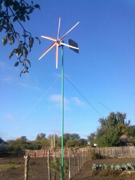
The height of the mast is approximately 6-12 m. It is installed in the center of the formwork and poured with concrete. Then a finished structure is installed on the mast, on which the screw is attached. The mast itself is fastened with cables.
Wind turbine blades
The efficiency of wind power installations largely depends on the design of the blades. First of all, this is their number and size, as well as the material from which the blades for the wind turbine will be made.

Factors affecting blade design:
- Even the weakest wind can set the long blades in motion. However, too much length can slow down the speed of the wind wheel.
- Increasing the total number of blades makes the wind wheel more responsive. That is, the more blades, the better the rotation starts. However, the power and speed will decrease, making such a device unsuitable for power generation.
- The diameter and speed of rotation of the wind wheel affects the noise level generated by the device.
The number of blades must be combined with the installation site of the entire structure. In the most optimal conditions Properly selected blades are able to ensure maximum efficiency of the wind generator.
First of all, you need to determine in advance the required power and functionality of the device. To properly manufacture a wind generator, you need to study possible designs, as well as climatic conditions in which it will be used.
In addition to the total power, it is recommended to determine the value of the output power, also known as peak load. It represents the total number of appliances and equipment that will be turned on simultaneously with the operation of the wind turbine. If you need to increase this figure, it is recommended to use several inverters at once.
DIY wind generator 24v - 2500 watts
We make a wind farm with our own hands in our private house. Let's get acquainted with the already existing industrial analogues on the market and with the works of craftsmen.
Mankind throughout its development does not stop looking for cheap renewable energy sources that could solve many problems of energy supply. One of these sources is wind energy, for the conversion of which into electrical energy, wind turbines have been developed. power plants(WPP), or, as they are more commonly called, wind farms.
Any person, especially those who have a private or country house, would like to have their own wind generator that provides affordable housing electrical energy. An obstacle to this is the high cost of industrial designs of wind turbines and, accordingly, the payback period is too long for an individual homeowner, making it unprofitable to purchase it. One of the ways out can be the manufacture of a wind farm with your own hands, which allows not only to reduce total costs for its acquisition, but also to distribute these costs over a certain period, since the work is carried out for a rather long time.
In order to make a wind farm, it is necessary to determine whether the weather conditions allow the use of wind energy as a permanent source of energy. After all, if the wind is rare for your area, it is hardly worth starting the construction of a homemade wind farm. If everything is fine with the wind, it is desirable to know the general climatic characteristics and, in particular, the wind speed, with its distribution over time. Knowing the wind speed will allow you to choose and make the design of a wind farm with your own hands.
Kinds
Do-it-yourself wind farm is classified according to the location of the axis of rotation and there are:
- with a horizontal arrangement;
- with a vertical position.
 Installations with a horizontal axis are called propeller-type installations and are the most widely used due to their high efficiency. The disadvantage of these installations is their more complex design, which makes home-made manufacturing options difficult, the need to use a mechanism to follow the direction of the wind and a large dependence of work on wind speed - as a rule, these installations do not work at low speeds.
More simple, unpretentious and slightly dependent on the speed and direction of the wind are installations with a vertical arrangement of the working shaft - orthogonal with the Darrieus rotor and carousel with the Savonius rotor. Their disadvantage is a very low efficiency, which is about 15%.
The disadvantage of both types of homemade wind farm is low quality generated electricity, requiring expensive options for compensating this quality - stabilizing devices, batteries, electrical converters. In its pure form, electricity is suitable only for use in active household load- incandescent lamps and simple heating devices. Electricity of this quality is not suitable for powering household appliances.
Structural elements
Structurally, regardless of the location of the axis, a home-made full-fledged wind farm should consist of the following elements:
- a device for orienting the wind turbine in the direction of the wind;
- a gearbox or multiplier for transmitting rotation from a wind turbine to a generator;
- DC generator;
- Charger;
- storage battery for electric power storage;
- inverter to convert DC to AC.
Features of the choice of current source
 One of the complex elements of a wind farm is a generator. The most suitable for DIY is a DC motor with an operating voltage of 60-100 volts. This option does not require alteration and is able to work with car battery charging equipment.
The use of an automotive voltage source is hampered by the fact that its nominal speed is about 1800-2500 rpm, and no wind turbine design can provide such a speed with a direct connection. In this case, as part of the installation, it is necessary to provide a gearbox or a multiplier of a suitable design to increase the rotational speed in the required dimensions. Most likely, this parameter will have to be selected experimentally.
A possible option could be a reconstructed induction motor using neodymium magnets, but this method requires complex calculations and turning work, which is often not acceptable. homemade work. There is a variant with phase-to-phase connection to the motor windings of capacitors, the capacitance of which is calculated depending on its power.
Manufacturing
Considering that the efficiency of a power plant with a horizontal axis has the best efficiency indicators, and the uninterrupted supply of electricity is supposed to be ensured by energy storage in battery, it is preferable for DIY manufacturing to be exactly this type of wind turbine, which we will consider in the framework of this article.
In order to make such a power plant with your own hands, you will need the following tool:
- electric arc welding machine;
- set of wrenches;
- a set of drills for metal;
- electric drill;
- hacksaw or angle grinder with a cutting disc;
- bolts with a diameter of 6 mm with nuts for attaching the blades to the pulley and the aluminum sheet to the square tube.
To make a wind farm with your own hands, you will need the following materials:
- plastic pipe 150 mm, length 600 mm;
- aluminum sheet with a size of 300x300 mm and a thickness of 2.0 - 2.5 mm;
- metal square pipe 80x40 mm and 1.0 m long;
- pipe with a diameter of 25 mm and a length of 300 mm;
- pipe with a diameter of 32 mm and a length of 4000-6000 mm;
- a copper wire long enough to connect an electric motor located on a mast 6 m long and the load that this current source will feed;
- DC motor 500 rpm;
- pulley for an engine with a diameter of 120-150 mm;
- 12 volt battery;
- car battery charging relay;
- 12/220 volt inverter.
The do-it-yourself manufacturing process is carried out in the following order:

Further, during the operation of the installation, it may be necessary to change the dimensions and configuration of the blades, the gear ratio between the wind turbine and the generator - each wind generator made by one's own hands is individual due to the use of various components and conditions of wind formation. Initially, a wind farm is recommended to produce a small power, on which you can work out the information received without investing a large amount of money.


 in the near future - forecasts and expert opinions")


 in the near future - forecasts and expert opinions")


