Purpose . Mnemonic diagram (screen form) is a visual graphic representation of the technological process, integrated with control and management tools. It is the most important source of information about the nature and structure of relationships, the current state of variables (including those associated with the violation of technological regimes, accidents, etc.) and allows the operator-technologist:
facilitate the memorization of the course of the technological process and the purpose of devices and controls;
determine the methods of action for various modes of operation of the object;
· Facilitate the simplification of the search and identification of the necessary information for promptly making the right decisions.
Graphic Components . All SCADA systems include tools that allow you to create both static elements of mnemonic diagrams (contour images of technological devices, pipelines, etc.) and animate (animate) these elements (create dynamic objects). These funds include:
· sets of graphical drawing primitives (line, rectangle, ellipse, curves, text) and means of their arrangement to create unique own objects);
Ready-made libraries of typical graphic objects: technological objects (apparatuses, mechanisms, machines, etc.), scoreboards, pointers, sliders, buttons, switches used to display variables and control the process. The library data can be extended by the user. When constructing a mnemonic diagram, drawing is first carried out
static image of the working window. Usually these are process devices or their technological sequence, pipelines, background, explanatory text, etc.
The next step is to give dynamics to the mnemonic diagram, i.e. animation of the drawn (or selected from libraries) elements. Animation refers to the ability of elements to change their properties when the process variables change. The properties that can be changed are the line width, color and style, the fill color and style (if it is a filled shape), and the size, position, and orientation of the elements. It also provides for direct input of variables (numbers and text, sliders) and process control using buttons and switches (Start / Stop, On / Off, Call Window, etc.).
Construction principles . With a wide variety of technological processes, designing a good mnemonic circuit is in many ways an art, but we can recommend general principles builds:
– conciseness and clarity- the mnemonic diagram should be simple (contours and proportions of the devices are close to the form of real prototypes), should not contain secondary elements, and the displayed information should be clear and specific, convenient for perception and further processing. The mnemonic diagram should provide a minimum, but adequate for control and management, number of variables, should not be “overloaded” with information for clarification (secondary trends), which is more convenient to do nested in the form of pop-up windows called at the request of the operator;
– maximum linearity process images, i.e. it is desirable to highlight the main line of the process, obeying the visual rule: reading "from left to right" and "top to bottom", the minimum use of parallel contours, which will greatly simplify perception
- autonomy– isolation from each other of the sections of the mnemonic diagram corresponding to autonomously controlled and managed objects and units. These isolated areas should be clearly separated from others and have a complete, easy to remember and distinct structure.
– unification- symbols of similar objects and processes should, if possible, be combined and unified;
- visual accent to control and management elements- First of all, elements that are essential for assessing the state, making decisions and affecting the managed object should be highlighted (in size, shape or color) (i.e. help to quickly navigate, identify and eliminate deviations and malfunctions);
– consideration of the human factor- the mnemonic diagram should be developed and improved taking into account the opinion of the operating personnel.
To evaluate mnemonic diagrams, the following are used:
– informative coefficient – the ratio of the number of passive (static) elements and active (dynamic);
– field filling factor – the ratio of the number of passive elements of mnemonic diagrams to the total number of elements of the mnemonic diagram.
When designing mnemonic diagrams, they usually offer several options. The final one is chosen by experiment (they simulate the operator's activity on the computer with various variants of the mnemonic diagram). The evaluation criteria are the time for solving problems and the number of errors made.

On fig. 2 shows the main zones of the mnemonic diagram. With a horizontal dominant of information presentation, the following zones are distinguished: basic information area- reflects the general structure of the technological process. It contains the main devices, pipelines, as well as the information load that accompanies the technological process.
additional information zone- buttons for trend charts, reports, start/stop, etc. can be located here.
switching zone- due to the impossibility of rationally displaying all information in one window (“format curse”).
With the help of area tools, it is possible to call additional windows on which alarms, trends (per day, month, year) are more detailed, separate sections process. This approach unloads the mnemonic diagram, makes it possible to obtain the necessary information about the object that deserves attention in this moment. A clear difference with the vertical dominant of the zones is that area 2 (additional information) is located to the right of area 1 (basic information). This is primarily due to the size of the described objects (the displayed process is small in volume), which allows more space for explanatory information. This arrangement of areas can be used for pop-up windows, i.e., a detailed examination of individual sections of the process.
- Mnemonic diagram - a set of signal devices and signal images of equipment and internal connections of a controlled object, placed on dispatcher consoles, operator panels or made on a personal computer. The information that is displayed on the mnemonic diagram can be presented in the form of an analog, discrete and relay signal, as well as graphically. Visually displaying the structure of the system, the mnemonic diagram makes it easier for the operator to memorize the schemes of objects, the relationship between parameters, the purpose of instruments and controls. In the control process, the mnemonic diagram is the most important source of information for the operator about the current state of the system, the nature and structure of the processes occurring in it, including those associated with violation of technological regimes, accidents, etc.
The mnemonic diagrams reflect the main equipment, signals, the state of the regulatory bodies. Mnemonic diagrams can reflect both the general picture of the state of the system, the technological process, and the state of individual units, devices, parameter values, etc. Auxiliary and reference material should be located in additional display forms, with the ability to extract these auxiliary forms to the screen as quickly as possible.
Mnemonic diagrams help the operator, working in conditions of a large amount of incoming information, to facilitate the process of information retrieval, subordinating it to a certain logic dictated by the real connections of the parameters of the controlled object. They facilitate the operator's logical systematization and processing of incoming information, help the implementation of technical diagnostics in case of process deviations from the norm, provide an external support for the development optimal solutions and formation of control actions.
Related concepts
A mnemonic shield (from the Greek μνημο - “memory”) is a dispatching equipment, an information visualization device designed to promptly display data on the state of the object of observation. It is a supporting structure with a dispatch object diagram (mimic) placed on it.
Read more: Mnemoshield
An electronic indicator (lat. indicator - pointer) is an electronic indicating device designed for visual control of events, processes and signals.
Adaptive control is a set of control theory methods that make it possible to synthesize control systems that have the ability to change the controller parameters or the controller structure depending on changes in the parameters of the control object or external disturbances acting on the control object. Such control systems are called adaptive. Adaptive control is widely used in many applications of control theory.
Data acquisition system (DSS; Data acquisition, DAS, DAQ) - a set of tools designed to work in conjunction with a personal computer or a specialized computer and perform automated collection of information about the values of physical parameters in given points object of study from analog and/or digital signal sources, as well as primary processing, accumulation and transmission of data.
Neurocontrol (eng. Neurocontrol) - special case intelligent control, which uses artificial neural networks to solve problems of managing dynamic objects. Neurofeedback is at the intersection of such disciplines as artificial intelligence, neurophysiology, theory automatic control, robotics. Neural networks have a number of unique properties that make them a powerful tool for creating control systems: the ability to learn from examples and generalize from data...
Access control and management system, ACS (Eng. Physical Access Control System, PACS) - a set of software and hardware security tools aimed at restricting and registering the entry and exit of objects (people, vehicles) in a given area through "passage points": doors , gate, checkpoint.
A vehicle malfunction indicator lamp (MIL), also known as a malfunction indicator lamp or CHECK indicator, is a signaling device for transmitting the status of a situation, mechanism or system.
Spectral division multiplexing (English wavelength-division multiplexing, abbr. WDM - wavelength division multiplexing) is a technology that allows you to simultaneously transmit several information channels one optical fiber at different carrier frequencies.
Telemechanics is the science of control and monitoring at a distance with the transmission (via a communication channel) of encoded electrical or radio signals that carry control information or data on the state of the controlled object. The objects of telemechanical control and monitoring can be technological processes, machines, devices, biological systems, etc.
The program selector is the node of the television receiver, which is entrusted with the tasks listed below ...
Network Control System (NCS - Network Control System) is control system, in which the control loops are closed through a communication network. hallmark NCS is that system components exchange control and feedback signals over a communication network in the form of packets.
Flexible manufacturing system (FMS flexible manufacturing system) is production system where there is some flexibility that allows the system to respond to product or technology changes, whether they are predicted or unpredictable.
An object communication device (USO) is a device in the process control system for combining analog and digital parameters of a real technological object. Designed to input signals from the object to the automated system and output signals to the object.
Plesiochronous Digital Hierarchy (PDH, also PDH from Plesiochronous Digital Hierarchy) is a digital data and voice transmission method based on channel time division and signal presentation technology using pulse code modulation (PCM).
A head tracking system (slang tracker, from English to track “track”) is an information input device for a personal computer that converts the user’s head movements into coordinates.
Damaged section indicator (UPU, IKZ - short circuit indicator, UTKZ - short circuit current indicator) - a device for determining the damaged section of the power line and signaling an emergency. Depending on the purpose and execution, short-circuit indicators are installed in a switchgear cell, on a support of an overhead power line or directly on the phase conductor of the line. In addition, UPUs are portable ...
A universal remote control (UPDU) is a type of remote control designed to control multiple home appliances. Unlike the classic remote control supplied with many types of home appliances, the UPDU is a standalone product and must be purchased separately.
Acoustic processor (eng. "Sound system processor") - electronic device or software package, designed to control multi-component sound reinforcement systems. The appearance of this class of devices is associated with advances in the development of sound amplification technology, where a large number of devices for correct signal routing, its division into frequency bands and other processing in accordance with the applied acoustic components complex system and those around...
Operator panel (Operator panel, slang. Panel or English HMI, also obsolete. Operator console) - a specialized computing device for mass (or large-scale) production, implemented as an industrial controller (rather than a computer), widely using a human-machine interface for control operators of individual automated devices or entire technological processes as part of automated process control systems in the framework of industrial automation.
Machine vision is the application of computer vision to industry and manufacturing. While computer vision is a general set of techniques that allow computers to see, the field of interest of machine vision, as an engineering branch, is digital input / output devices and computer networks designed to control production equipment, such as robotic arms or devices for extracting defective products. Machine vision is a subset of engineering...
Satellite monitoring of transport - a system for monitoring moving objects, built on the basis of satellite navigation systems, equipment and technologies for cellular and / or radio communications, computer science and digital maps. Satellite monitoring of transport is used to solve transport logistics problems in transportation management systems and automated fleet management systems.
A servo control system is an automatic control system in which the controlled variable reproduces an arbitrarily varying driving force.
The main parallel interface (MPI) is a standard that defines a set of lines and procedures for exchanging a processor and peripheral modules inside a computer using a combined (multiplex) address and data bus. The standard provides for an exchange rate of up to 5.6 MB / s with a transmitted data width of 8 or 16 bits and an address width of 16 to 24 bits and was focused on use in systems of low and medium performance. The requirements of the standard are set out in OST 11.305.903-80 and GOST ...
Onboard means of objective control (onboard SOK), also Control and recording equipment (KZA) - technical means, designed to record and store flight information characterizing flight conditions, crew actions and the functioning of on-board equipment. SOC are used for: analysis of the causes and prevention of flight accidents; technical diagnostics of onboard equipment and its forecasting technical condition; assessment of the actions of the flight crew when performing ...
Shutdown, shutdown (from the English. shutdown) - the operation of a regular or emergency termination of the computer system, as well as operations preceding it.
Power line communication, PLC (Eng. Power line communication) - a term describing several different systems for using power lines (TL) to transmit voice information or data. The network can carry voice and data by superimposing an analog signal on top of standard 50Hz or 60Hz AC. The PLC includes BPL (Broadband over Power Lines - broadband transmission over power lines), which provides data transfer at speeds up to 500 Mbps, and NPL (English ...
Technologies for protecting telephone conversations are methods and means of protection aimed at ensuring the confidentiality of information exchange between subscribers. The control of telephone conversations remains one of the most common types of industrial espionage and the actions of criminal elements. The reasons are simple - low costs and the risk of threats, the need to enter a controlled room, a variety of ways and places to collect information, etc. You can control telephone conversations ...
A video wall is a system of video display devices (projection video cubes, plasma or LCD displays) that are interconnected and form a single screen that allows you to play large amounts of information in multi-window mode from different sources. A large number of video signal sources is very important when using the system for quick decision making. In comparison, a traditional projector can use a maximum of three sources.
Spacecraft information transmission system - a set of software and hardware that allows you to transfer information between a spacecraft (SC) and the flight control center of this spacecraft.
Indicating device - a set of elements of a measuring instrument that provide visual perception of the values of the measured quantity or quantities associated with it.
A technical system is an artificially created system designed to meet a specific need, existing 1) as a product of production, 2) as a device potentially ready to perform a useful effect, 3) as a process of interaction with environmental components, which results in a useful effect.
Monitoring is a system of continuous monitoring of phenomena and processes taking place in environment and society, the results of which serve to substantiate ...
A user-programmable gate array (FPGA) is a semiconductor device that can be configured by the manufacturer or developer after manufacturing; hence the name: "user-programmable". FPGAs are programmed by changing the logic of the circuit diagram, for example, using the source code in the design language (such as VHDL), which can be used to describe this logic of the microcircuit. FPGA is one of the architectural...
Channel-associated signaling, also known as per-trunk signaling, is a type of signaling in digital communications. Like most telecommunications signaling methods, it uses routing information to direct voice or data payloads to their destination. At this type signals, the routing information is encoded and transmitted on the same channel as the payload. This information can be shared...
Control system - a systematized (strictly defined) set of tools for collecting information about a controlled object and means of influencing its behavior, designed to achieve certain goals. The object of the control system can be both technical objects and people. The control system object may be composed of other objects, which may have a permanent relationship structure.
Positional tracking is one of the virtual reality technologies that underlies human interaction with the virtual world. Designed to determine the position and orientation of a real object (for example, a hand, head or a special device) in a virtual environment using several degrees of freedom. As a rule, three coordinates of its location (x, y, z) and three angles that define its orientation in space (“roll”, “pitch”, “yaw” or Euler angles). Definition...
Telemetry, telemetry (from other Greek τῆλε “far away” + μέτρεω - “I measure”) - information about the values of the measured parameters (voltage, current, pressure, temperature, etc.) of controlled and controlled objects by methods and means of telemechanics. The term is derived from the Greek roots "tele" - "remote" and "metron" - "measurement". Although the term itself in most cases refers to the mechanisms for wireless transmission of information (for example, using radio or infrared systems), it also includes ...
Relay protection is a set of devices designed for quick, automatic (in case of damage) detection and separation of damaged elements of this electric power system from the electric power system in emergency situations in order to ensure normal operation the entire system.
Designation:
SShMK.421457.008-DShch
As part of automated system power supply management (ASUE) of the software and hardware complex "Kosmotronika" (PTC "Kosmotronika") provides for various jobs for specialists, including workplace dispatcher - dispatching mnemonic shield.
The dispatching control panel is used for operational visual control and automatic registration of information about the state of objects included in the dispatch control system. reflects circuit diagram power supply of substations of association with necessary level detail, equipped with telemechanics and light elements that allow you to record operational switching in automatic mode.
|
Picture 1. Appearance control panel |
||
The main functions of the mnemoshield:
- visual display of the power supply scheme for supervisory control objects,
- registration of object states for the operator to perform the functions assigned to him;
- displaying the links and nature of the interaction of the managed object with other objects;
- signaling about changes in the operation of objects;
- rapid identification of the possibility of localization and elimination of faults.
The composition of the mnemonic shield
Dispatch control panel is modern modular design and differs in the increased reliability and quality of production. Consists of the following main units:
- supporting structure;
- self-supporting facade with a printed graphic scheme;
- control systems, including the mimic board controller, indicator control modules;
- power systems;
- software.
The composition of the equipment set depends on the parameters of the ordered mnemonic board, based on the developed project documentation.
Basic structure
The supporting structure of the shield is made of light steel profiles, interconnected with screws and special connecting elements. All elements of the supporting structure are protected from corrosion.
A set of structural profiles allows you to mount the supporting installation of any free-standing control board with a height of not more than 6500 mm and a radius of curvature of the facade of not less than 6000 mm, the length of the shield is not limited. The height and length of the shield can be changed in increments of 24 mm, while the radius of curvature of the facade can change smoothly. It is possible to make a shield with a changeable radius of curvature of the facade, for example, along a hyperboloid. The typical shield width is 580 mm if the shield is over 3000 mm high. For lower panels, the depth can be reduced to 400 mm.
Figure 3:
H - full height shield, L - the total length of the shield, without restrictions;
s - height of adjustable props, from 30 to 80 mm;
p - stand height, > 0;
g - thickness of the edging of the facade, 5 mm;
But - the height of the facade, n × 24 mm;
Lo - facade length, m×24 mm.
In the standard version, the load-bearing structure of the switchboard is open at the rear. On request, it is possible to produce a structure completely covered with roll-up screens. Execution options are shown in Figure 4.
Figure 4: 1 - direct location;
2 - curved shield with a bending radius of at least 6000 mm;
3 - broken shield.
|
Figure 5. Example of a self-supporting facade |
||

Self-supporting facade
The facade is built from mosaic elements with a module size of 24×24 mm. Mosaic elements are made of flame retardant ABS or PC plastic. Each element consists of a body and a mosaic chip. The housings are equipped with a system of clamps that ensure their interconnection, fastening of the mosaic chip, connection with the active module (alarm), as well as fastening of the elements that serve to connect the facade with the supporting structure of the dispatcher board. An example of a self-supporting facade is shown in Fig.5.
The facade is mounted to the upper and lower edges of the supporting structure in a strip two modules wide using leveling pins (4 pieces/m). The design of the facade allows you to mount in its plane a large number of typical measuring instruments, pointers, regulators and monitors. The thickness of the self-supporting facade is 37 mm.
Facade elements of the shield can be as follows:
- passive chips (various elements of schemes, letters and numbers of any colors);
- LED modules (passive chips with circuit elements and holes for LEDs and LEDs different colors and sizes);
- digital indicators (of different heights and the number of displayed digits);
- rotary elements (used to display non-telemechanized switching devices);
- portable chips.
Control system
Designed to transfer data from the top-level software of the supervisory control system and display them on the control board.
Consists of the following elements:
- control modules for LED indicators (UDS-1);
- digital indicator control modules (UDS-2);
- interface converters;
- optical probe;
- control room controller.
|
|
Designation:SShMK.468153.021 Short description:Designed to control the operation of individual LEDs, receive and transmit data via the RS-485 interface with an exchange rate of 1200 to 115200 bps. Provides function of two modes of brightness of a luminescence of light-emitting diodes: day and night. In the process of setting up the control panel, it gives the module number and channel number of a particular LED. It has a self-control mode (reading the state of the module's memory), as well as an echo mode (confirmation of the operation of the LED). Additionally, it has the ability to read data from an ambient temperature sensor, transfer via RS-485 and further display on the shield indicator. |
|

- Number of channels: 64
- Module power supply: 5V±0.25V
- Maximum distance from the server at a data transfer rate of 115200 bps: 100 m
- Dimensions: 202 x 113 x 38 mm
- Module weight: 200 g
|
|
Designation:SShMK.468153.031 Short description:Designed to control the operation of digital indicators, receive and transmit data via the RS-485 interface with an exchange rate of 1200 to 115200 bps. Provides the function of two modes of brightness of the glow of digital indicators: day and night. In the process of setting up the control panel, it gives the module number and channel number of a particular indicator. Additionally, it has the ability to read data from an ambient temperature sensor, transfer via RS-485 and further display on the shield indicator. |
|

- Number of channels: 64
- Number of seven-segment characters controlled by one module: 8
- Switching current (day/night): 20mA / 10mA
- Module power: 5V±0.25V or 12V±1V
- Maximum distance from the server at a data rate of 115200 bps: 100 m
- Maximum number of modules in one RS-485 circuit: 256
- Self-monitoring time of one module: 0.2 sec
- Temperature range measured by the sensor: -55 ... +125С
- Sensor temperature measurement accuracy: 0.5С
- Temperature conversion time: 750ms
- Power consumption: no more than 6.5 W
- Dimensions: 202 x 113 x 38 mm
- Module weight: 200 g
Module for converting the RS-232 interface into the RS-422/485 interface
- 1 "RS-232" port (RXD and TXD lines)
- 1 RS-422/485 port (RXD and TXD lines)
- Maximum baud rate: 115200 bps
- Galvanic isolation: not less than 2500 V
- Module power supply: 5V±0.25V
- Power consumption: no more than 0.5 W
- Dimensions: 70x50 mm
- Operating temperature range: -40 С ... + 85 С
- Module weight: 50 g
optical probe
The optical probe is used in the process of setting up the control panel. Designed to determine the addresses of LED indicator control modules and their channels, with subsequent recording of the information received in the database of the Telemechanics workstation. The probe is a photo sensor with an open optical channel that converts the modulated light flux into an electrical signal and transmits it to the controller.
Control room controller
Personal computer with installed software of PTC "Cosmotronics". Performs the role of a control controller, receiving data via the local network, and issuing them to the UDS-1 and UDS-2 modules via the RS485 interface. A separate port is intended for connecting an optical probe during commissioning.
Supply system
The mnemoshield is powered by 220V alternating current. Sockets are installed on each section of the control panel, to which a power cable is connected. Power supplies are connected to sockets. Each PSU can be connected from one to several control modules.
To implement the function battery life The mnemoshield is equipped with a source (s) of uninterruptible power supply.
Voltage transformer
Designed to power the LED indicator control module, digital indicator control module and interface conversion module.
Short description:
The 220/24V power supply is used to convert the 220V AC mains voltage into a stabilized 24V voltage. It has a built-in battery charger. Metal housing, mounted on a DIN rail.
Main technical characteristics:
- Input and output circuits are galvanically isolated
- Provides limitation of the initial impulse of current and voltage
- Output short circuit and overvoltage protection
- Built-in battery charger module
- Input voltage
- AC: 90…264 V
- DC: 110…370 V
- AC input frequency: 47…63 Hz
- Output voltage: (24±1)V
- Output voltage (battery): 19…30V
- Maximum output current, A: 2.0
- Output current protection threshold, A: ≤2.4
- Battery capacity, Ah
- recommended: 1.3
- maximum: 4.5
- Overload protection: yes
- Overvoltage protection: yes
- Battery overcharge protection: yes
- Battery health test: yes
- No input power output: yes
- Discharge and battery failure monitoring output: yes
- metal body
- Case protection degree: IP20
- Mounting method: 35mm DIN rail
- Dimensions: 112 x 57 x 120 mm
- Weight: no more than 300 g
- Operating temperature range: -40°C ... + 65°C
Software
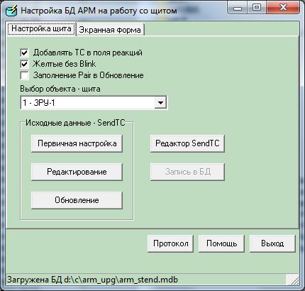
The software for controlling the dispatcher's mnemonic board is integrated into the automated control system of the PTK "Kosmotronika" and is included in the software of the AWP "Telemechanika". In the settings of the "Telemechanics" workstation, the "Shield control editor" module is activated. Therefore, when the dispatcher is running, there is no need to run third-party mnemonic control programs.
If the dispatcher board is supplied as part of a third-party dispatching system (not Cosmotronics), then the Customer is provided with the necessary software for integration with the top-level software system using standard protocols.
During the initial launch of the mimic board software and reconfiguration of the dispatcher mimic board during operation, it is necessary to use (configure) the following programs:
- Communication server "Cosmotronics";
- "Setting up the AWS database for work with a shield";
- "Setting up the control panel".
Communication server "Cosmotronics"
|
|
||

The communication server is an intermediate link between the control panel controller, UDS-1, UDS-2 modules and the top-level program of the AWP "Telemechanics". It performs the following functions:
- organization of communication with the existing data collection system
- organization of communication with controllers via various communication channels
- periodic testing of the communication channel and checking the status of communication with subscribers
- maintenance of the system protocol and the protocol of communication channels operation
- receiving information about the automation object from controllers
- entering information into a database
- retransmission of received data in various protocols to remote servers, workstations, control panels
- relaying telecontrol commands to controllers
- parameterization of controllers
- displaying the status and operation modes of communication channels in various windows
In addition, through the communication server, integration with third-party systems is carried out using standard protocols.
Configuring the AWP database to work with a shield
|
The window of the program "Configuring the DB AWS to work with a shield" |
||
The program "Setting up the AWP database to work with the shield" is a part of the AWP "Telemechanika" software and is designed to automate the routine process of compiling tables in the AWP settings database and screen forms when preparing to work with the shield.
Control panel setup
|
Window of the program "Control panel settings" |
||

The program is designed to automate the process of assigning LED outputs to USO (UDS-1) contacts during installation or reconfiguration of the switchboard. Using an optical probe, the USO number and channel number are determined. It is also possible to manually enter the USO number and channel number. The results of the assignment are entered into the tables of the AWP settings database for further use in the Telemechanics AWP. At any time, it is possible to visually check the correct binding of a specific signal by selecting it in the table and issuing a command to turn on the LED.
Software for maintaining a mnemonic diagram and an electronic journal of an energy facility
The dispatching information system is an integral part of the Modus software package. It is based on the application maintaining a mnemonic diagram and an electronic journal dispatcher.
Mimic diagram and electronic logging software, together with a set of extensions described in sections Integration with databases, Working with remote control data and other extensions, is dispatching information system.
The operation of the program is based on the maintenance by the operator of the operational scheme of the power facility, presented in graphical form (mimic). The operator makes changes to the scheme in accordance with the change in the state of the power facility. It is possible to connect a system for collecting telemetric information, as well as a telecontrol system, in which case the program acquires the capabilities described in the section Working with remote control data.
The electronic journal is filled in automatically in accordance with changes in the operational scheme.
The software is focused on maintaining schemes of any level - PES, RES, urban electrical networks, power supply schemes for industrial enterprises, power systems, substations, electrical circuits of stations, relay protection and automation equipment, SDTU devices.
The software is of particular benefit in those enterprises where there are big schemes power supply with a relatively small amount of telemechanics. First of all, these are city networks, distribution networks, industrial enterprises.
Previously, this application was called the Electronic Journal, and before that the Operative Journal. Currently, these names are not used, as they do not accurately convey the main purpose of the program.

Mimic diagram management software
Key features:
- Allows you to keep records of switching both on the primary (switching devices) and on the secondary (state of relay protection and automation) circuits;
- Provides verification of the feasibility of performing operations based on the rules of switching in electrical installations;
- Allows switching according to forms or switching programs, or step by step;
- Allows you to keep a record of the location of the ASO, repair teams, sites repair work, accident sites, installed portable protective grounding;
- Allows you to maintain power facilities on the diagrams
- It has advanced means of printing circuit states (normal, operational, on given moment time), provides search and selection of circuit elements on the circuit according to a number of criteria;
- Provides printing of the Electronic Journal, generation of reports on the data available in it.
Service log functions
- Examples of log selections:
- from the moment of registration of the operator in the system;
- from the previous registration of the operator in the system;
- changes in the operational scheme for specified period time;
- related to the difference between the operational scheme and the normal one;
- emergency switching;
- Installed/removed portable grounding, enabled/disabled SA. - Display of de-energized and grounded areas
- Export selections as files.
- Quick transition between entries in the journal, elements of the scheme and items in the switching forms.
- Display of deviations of the state of the operational scheme from the normal scheme and from the state at the time of the last shift delivery.
- Printing and displaying mnemonic diagrams of an object
- In the state at the specified point in time
- In the current state of the operational scheme
- In the normal state of the circuit
- Display equipment that is faulty, de-energized, busted, unused, etc.
- Display of cable chains and overhead lines and transformer substations included in the feeder
- Display in the tooltip of the SS, the supply center and the RP from which the feeder is powered
- Diagnosis of incorrectly powered feeders
- Ability to view the current state of the schema and log by other users on the network.
Service functions of the circuit
- Displaying the result of the selection directly on the diagram.
- Viewing data associated with the elements of the scheme (for example, passport or calculated data) from databases available to the customer. The standard mechanism for connecting such bases is built into the software.
- On-the-fly chart display (no redrawing) customization according to enterprise standards or operator preference.
- Automatic placement of line directions from the supply center to the consumer
- Automatic formation and illumination of normal (according to normal current sections) and current (at a certain point in time) feeders.
- The complex provides for a multipage system of transitions from the general network scheme to the geographical map of the area.

Organizational and technological tasks to be carried out:
- Approval of the normal scheme and the admission of users to work.
- Acceptance (delivery) of the shift by the operational personnel of the facility, transfer of information on the shift.
- Maintenance of the operational scheme, maintaining an electronic journal.
- Using the system for preparing and fixing the execution of standard and one-time switching forms and switching programs.
- Maintaining a list of current tasks.

Types of journal entries
- Marking accident sites.
Actions with objects - fixing switches, setting the removal of operational current / blocking, setting the removal of protection, etc.
Acknowledgment of TV signals and messages about exceeding the values of the settings.
Verification actions, results of rounds and inspections.
Negotiations between operational personnel, orders.
Arrangement and accounting of field and repair teams at destinations.
Installation / removal of mobile elements - portable grounding, poster, looping, etc.
Task editor
As part of the software for maintaining a mnemonic diagram and an electronic journal, the program "Editor of Operational Tasks" is implemented. It is designed to monitor the status of operational tasks at the dispatcher's workplace.
The software allows:
Compilation of operational tasks by performing operations on the electronic layout of the power facility.
Verification of the operational task according to the mnemonic diagram (layout) with control over the correctness of the operations:
switching on the grounding knives under voltage;
disconnecting disconnectors under load;
operational blocking control;
showing on the diagram with a dotted line of disconnected electrical sections of the circuit, etc.
Marks of the execution of operations in operational tasks, which ensures control over the real state of active operational tasks.
Quick access and switching between active tasks.
Saving the active task to a file and loading from a file up to date.
Ability to view mnemonic diagrams of power facilities.
Possibility to print an operational task in the form of a switching form of a standard form.
Compilation of regular switching forms and work with them.
Preparation and storage of a database of standard switching forms.
Checking the possibility of performing a typical switching form in the current state of the power facility scheme.
Creation of regular switching forms based on standard forms in in electronic format and work on them.
The program provides control over the status of several simultaneously executed operational tasks. The dispatcher can switch between them in the task list window. The editor of operational tasks is integrated with the software application for Maintaining a mnemonic diagram and an Electronic Journal.
Additional journals included in DIS
Starting from version 5.20, DIS includes a number of additional journals:
- Changes in the power supply of consumers,
- Technological violations,
- consumer applications,
- Hardware defects..
The data of additional logs are stored in the EZH database and contain information about the parameters and time of the event, the power facility, an explanatory part, data about the person who made the entry:
The developed journals are fully integrated with electric circuit. Automatic transition from a log entry to a schema element and vice versa is provided. It is also possible to work logs without schema.
All journals allow you to generate reports in Word format
Power Supply Change Log
The power supply change log allows you to keep track of changes in the power supply of consumers.

Power Supply Change Log Form
Log of registration of technological violations
In the journal of technological violations (TN) are recorded:
- Time of occurrence of TN
- The object of the occurrence of TN
- Number of de-energized transformer substations, substations, healthcare facilities, heat supply
- Disconnected power
- Time to eliminate the TN commissioning the object
Data of the report on de-energized subscribers are formed automatically on the basis of pre-prepared directories of subscribers and analysis of the current network configuration.

Form of the log of technological violations

The form of recording the log of technological violations
Journal of consumer applications for power failure.
To organize the process of registering consumer applications in the DIS, an appropriate module has been developed that allows you to record information about the complete or partial loss of power supply using corporate information systems formed at enterprises.

Consumer Application Log Form

Consumer Request Log Record Form
Log of defects and problems with equipment and the progress of their elimination
A module for registering defects and malfunctions with equipment, fully integrated with the electrical circuit, has been developed. At the same time, an automatic transition from the record to the circuit element and back is provided.
The module provides the ability to select records by:
- the planned date of elimination of the defect (indicating a specific date or indicating a period),
- department responsible for troubleshooting
- all unrepaired defects, defects whose elimination period has expired;
The module allows you to postpone the deadline for fixing a defect.

Defect log form 
Defect log entry form
Security and legal aspects
All changes to the log are entered on behalf of the dispatcher who took over the shift. Forgery and retroactive alteration of entries in the electronic journal are excluded. For insurance against software failures, it is possible to maintain a hard copy (print) simultaneously with logging entries.
Connection of telesignaling / telecontrol
control room information system can be considered as constituent part OIC (upper level), which implements support for operational switching and has wide opportunities integration.
AT software built-in ability to receive teleinformation and telemetry, as well as remote control of energy facilities through the industrial software interface OPC. This programming interface is supported by many modern complexes telemechanics, as well as OIC / SCADA systems.
The exchange of such complexes is carried out without additional programming. In the case of using information from systems that do not support OPC, docking can be carried out on a contractual basis by Modus developers or another contracting organization (development of an appropriate OPC server is usually optimal).
Thus, the software package can be considered as an integral part of the OIC (upper level), in which support for operational switching is implemented.


 in the near future - forecasts and expert opinions")


 in the near future - forecasts and expert opinions")


