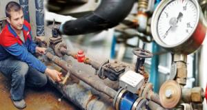
To check pipelines for tightness and strength, they are carried out under pressure with water and gases.
In most cases, work is carried out hydraulically.
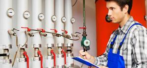
Pneumatic is used in cases where:
- air temperature below 0 degrees;
- No the right amount water;
- created high voltage in a pipeline or supporting structure;
- when tested with air or gas according to the project.
Rules for conducting, according to SNiP
 When conducting hydraulic tests, the pressure is set equal (in the absence of parameters in the project):
- for pipelines made of steel operating with a pressure of less than 0.5 MPa, for systems operating with a temperature of more than 400 degrees, regardless of pressure - 1.5 bar;
- for a steel pipeline with a pressure of more than 0.5 MPa - 1.25 bar, but not less than 0.8 MPa;
- for pipes of another design - 1.25 bar.
During strength tests, the pressure is maintained for 5 minutes, then reduced to working pressure, the pipes are inspected.
Pressure for glass pipes is kept for 20 minutes.
The remaining pipelines are tapped along the seam with a steel hammer weighing up to 1.5 kilograms, non-ferrous metal pipes - with a wooden weight of 800 grams.
Pipes made of other materials are not tapped.
Result hydraulic test it is considered satisfactory if during the inspection no pressure drop is noticed, there are no leaks and fogging in the seams, housings, seals ().
At the end of the work, a certificate of acceptance of the pipeline into operation is necessarily drawn up..
The pressure is built up to the specified, then the pipes are disconnected from the water supply or pressure testing device.
Checking plastic
During the test plastic pipes (soldering video polypropylene pipes see with your own hands) the right pressure achieved by pumping water.
If the tests are carried out in the cold, then measures are taken to prevent freezing of water: heating, additives,.
FACT. Large gas and oil companies develop instructions with the participation of specialized specialists based on theoretical calculations and experimental studies.
Main pipelines- sources of risk, therefore, strict requirements are imposed on the operation of such communications.
Pneumatic test
carried out with air or inert gases.
Checking the strength, tightness is prohibited in working shops, on a flyover, in a channel, a tray where pipes lie.
 Gas pressure depends on pipeline parameters, materials.
In general, it is equal to the pressure during hydraulic tests.
Calculations and formulas
Maximum length of the inspected section, pressure limit values for pneumatic testing overhead pipeline depends on the diameter of the pipes and is calculated by the formulas:
![]()
where:
- Pmin - pressure for testing in MPa;
- Kn - reliability factor from table 11 of SNiP 2.05.06-85;
- n is the reliability factor under loads from table 13 of SNiP 2.05.06-85;
- m is the coefficient of operating conditions from table 11 of SNiP 2.05.06-85;
- Pwork - the maximum value of the working pressure in MPa.
The length of the section to be checked is calculated by the formula:
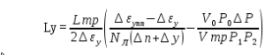
where:
- NL - the number of sheets per pipe, two-seam NL = 2, other types NL = 1;
- Ltr is the length of the checked section, m;
- ∆P – errors in measurements of pressure addition;
- ∆y are errors in volume gain measurements;
- ∆ε y is the deformation of the pipe with changes in pressure by the index P;
- Р 1 , Р 2 - successive pressure measurements, Pa;
- ∆εupp is the allowable deformation of pipes with an increase in pressure by the index P;
- P 0 - atmospheric pressure, Pa;
- V 0 - the possible volume of air that remained in the pipeline, at Р 0, m3.
 Pneumatic strength test if cast iron fittings are installed, it is carried out at a pressure of not more than 0.4 MPa.
After checking, tapping is prohibited water pipes(which is better for hot water supply, it is written) with a hammer until the pressure is reduced.
IMPORTANT!
The formulas used in the calculations, the coefficients may vary, depending on the field of application of materials, test developers.
It is necessary to use a mathematical tool designed for specific pipelines (automatic irrigation systems - read how to do it yourself).
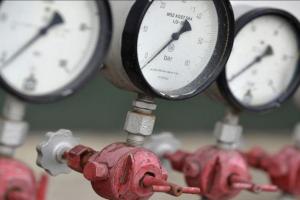
Maximum allowable pressure
Gas test pressure raise gradually with constant inspection of the pipes: 30% of the maximum pressure, 60% of the maximum pressure and the peak value.
On examination, the increase in pressure stops.
The last inspection is carried out at operating pressure., and combine it with a leak test. Defects are detected with a soap solution or other means.
Defects of transverse seams found during testing are not corrected.
A section of the pipe with damage is cut out, and a new segment is replaced.
 The length of the section between the seams should be at least 20 centimeters with a pipe diameter (which is recommended for plumbing in an apartment is written in the article) over 150 millimeters.
With a smaller diameter, the straight section should be at least 10 centimeters.
Long term maintenance high pressure , pipes, constantly, are inspected.
If the pressure has increased due to heating, then the test pressure is reduced smoothly (read about the causes of water hammer in the pipeline) to the required level.
Requirements for the organization of the place
The tests are carried out in a fenced protected area, regardless of whether the test is carried out indoors or outdoors.
Access of people to the test site is prohibited.
The minimum boundary of the protected area for above-ground tests is 25 meters, for underground tests - 10 meters.
Borders should be marked with flags and control posts. Posts are installed - one post per two hundred meters of the pipeline.
At night time provide quality lighting borders and the test area itself.
Compressors for creating test pressure are placed outside the security zone. Lines from compressors are preliminarily checked hydraulically.
Outcome
Detection of leaks, fogging leads to an unsatisfactory evaluation of the test. Inspection of pipes is carried out by specially trained employees. Upon completion of the tests, an act is drawn up in the prescribed form.
See how pipelines and fittings are tested at the stands of a company that produces metal-plastic pipes and accessories.
During the construction of pipelines far from water sources, as well as in winter, when the water freezes, pipelines are tested compressed air.
If, during the final test, it is not allowed to raise the pressure in the pipelines to the test one according to safety regulations, then combined tests are carried out: preliminary - pneumatic (compressed air), and final - hydraulic (water pressure).
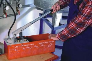
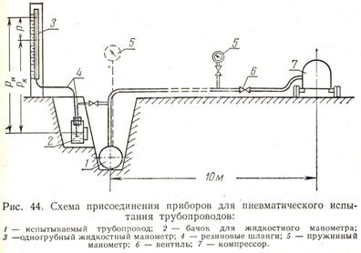
To carry out a pneumatic test, the following is required: a compressor, two spring pressure gauges - one on the pipe for supplying compressed air from the compressor, the other at the opposite end of the pipeline section being tested; single-tube liquid manometer; tank for liquid manometer(Fig. 44).
Preparation of pipelines for pneumatic testing is carried out in the same way as for hydraulic testing.
The length of the test section in the pneumatic method for asbestos-cement, cast iron and steel pipes should not exceed more than 1 km, and for polyethylene - no more than 0.5 km. During the test, the pipes should be sprinkled with soil 30-50 cm above the shelya, and only the joints of the pipelines are allowed to be left open.
Defects in the tested section of the pipeline are detected by one of the following methods:
By the sound of escaping air;
On bubbles of soap emulsion, which is applied immediately before testing on butt joints;
By the smell of leaking odorized air (on any pipelines, except polyethylene).
The odorant in the form of ammonia, ethyl mercaptan and other gases is added to the air supplied by the compressor during testing.
The pneumatic test is carried out in the same two stages as the hydraulic test: preliminary and final. The final test is acceptance. The pressure in the pipelines during their testing should increase gradually in steps of 0.2 of the test pressure, at intervals of 5 minutes.
Strength testing of steel pipelines at a working pressure of up to 5 kgf / cm 2 is carried out with a test pressure of 6 kgf / cm 2, and at a working pressure of more than 5 kgf / cm 2 - with a test pressure 15% higher than the working one. First, the pressure is increased to the test pressure and the pipeline is kept under it for 30 minutes. Then the pressure is reduced to 3 kgf/cm 2 and the pipeline is inspected.
The final test is carried out in the following order.
1. The pressure is increased again to the test pressure and the pipeline is kept under this pressure for 30 minutes. Then the pressure is reduced to 0.5 kgf / cm 2 and the pipeline is kept under this pressure for 24 hours.
2. Increase the pressure again to 3000 mm of water. Art. (when filling the liquid manometer with water) or up to 3450 mm of water. Art. (when filling it with kerosene).
Under this pressure, the pipeline is maintained for a certain time, which for pipes made of different materials and different diameter established by the regulations. After this time, the pressure in the pipeline and the barometric pressure are measured using pressure gauges, and the amount of pressure reduction is calculated using the formula
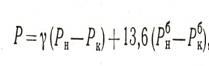
where Рн and Рк - pressure in the pipeline at the beginning and at the end
tests;
The pipeline is considered to have passed the test if no violation of its integrity is detected, and the pressure drop does not exceed the allowable value.
Trial cast iron pipes pipelines can be carried out pneumatically if operating pressure in them does not exceed 5 kgf / cm 2. At a higher working pressure, only a preliminary test is carried out pneumatically, and the final test is carried out hydraulically.
When conducting a preliminary test (before backfilling the trenches), first increase the pressure to 1.5 kgf / cm 2 and hold the pipeline under it for 30 minutes. Then this pressure is reduced to 1 kgf/cm 2 and the pipeline is inspected.
The final test of cast-iron pipelines in a pneumatic way is carried out after filling the trenches in the same order as steel ones, but at a test pressure not higher than 6 kgf / cm 2.
Pneumatic testing of asbestos-cement pipelines is allowed if the working pressure in them is not higher than 5 kgf / cm 2.
The preliminary test (strength) is carried out under a test pressure equal to the working pressure plus 2 kgf/cm 2 , but not more than 6 kgf/cm 2 . First, the pressure is increased to 1.5 kgf / cm 2, after which it is reduced to 1 kgf / cm 2 and the pipeline is inspected. Defects are removed by atmospheric pressure in the pipeline.
The final test of asbestos-cement pipelines is carried out in the same way as for cast iron.
Trial polyethylene pipelines pneumatic method is allowed to be carried out only for strength, not earlier than two hours after the last welding in the test area and without air odorization. The final test (density) should only be carried out hydraulically.
The preliminary pneumatic test is carried out at a test pressure 50% higher than the working one, but not more than: for pipes at a nominal pressure of 6 kgf / cm 2 - 9 kgf / cm 2; for pipes for a nominal pressure of 2.5 kgf / cm 2 - 3.8 kgf / cm 2.
The pipeline is kept under test pressure for 30 minutes. Then the pressure is reduced to 3 kgf/cm 2 and the pipeline is inspected. Defects are eliminated at atmospheric pressure in the pipeline.
The pipeline is considered to have passed the test if no leaks or other defects are found on it.
Page 2
Pneumatic tests are more responsible than hydraulic tests and aim to test the pipeline for tightness or strength. The pressure in the pipeline is created by filling it with compressed air or an inert gas, most often nitrogen. To carry out the test, mobile devices are connected to the pipeline. air compressors or other sources of compressed air or compressed gas. The supply of compressed gas is carried out in accordance with the requirements for temporary pipelines under pressure.
Pneumatic strength testing of pipelines located in existing workshops, as well as on overpasses, in channels and tunnels next to existing pipelines, is not allowed.
Pneumatic tests for the strength and tightness of the connection are carried out by pressure testing with air on a special stand. It is advisable to test a series of flanges simultaneously.
Pneumatic tests are explosive and therefore carried out in separate rooms or in fenced areas of the workshop. Air ducts are supplied safety valves and verified manometers.
Pneumatic test is different heightened danger, which increases when used for testing natural gas. Then, in addition to the destruction of the pipeline, explosions and fires are possible. The destruction of the pipeline during pneumatic testing occurs with the ejection of soil and metal over considerable distances.
The pneumatic test is carried out with compressed air at the working pressure of the vessel. The density of the seams is checked by smearing them with a soapy solution or immersing them in water, if the dimensions of the vessel allow this. Bubbles form in places of leaks. For safety reasons, a pneumatic test is performed only after a preliminary hydraulic test of the vessel.
Pneumatic testing is carried out twice: preliminary - with powdering of pipes and final - after backfilling of trenches. Pipelines made of cast iron pipes can be tested by pneumatic methods if the working pressure in them does not exceed 0 5 MPa (5 kgf / cm2); with a higher working pressure, only a preliminary test is performed pneumatically, and a final test is carried out with water.
Pneumatic testing is carried out twice: preliminary - with powdering of pipes and final - after backfilling of trenches. Pipelines made of cast iron pipes can be tested by pneumatic methods if the working pressure in them does not exceed 0 5 MPa (5 kgf / cm2); with a higher working pressure, only a preliminary test is performed pneumatically, and a final test is carried out with water.
The pneumatic test shall be carried out with air or an inert gas and only during daylight hours.
Pneumatic testing is carried out according to several schemes, depending on the air or gas source used. Sources of natural gas for testing gas pipelines can be: gas fields; operating gas pipelines, to which the pipeline under construction is connected - branch; an existing gas pipeline crossing a pipeline under construction or passing in close proximity to it.
Pneumatic tightness test after tightening the flanges, which is accompanied by washing of welded and brazed seams, flanged joints of vessels, apparatus and pipelines.
The pneumatic test is carried out with air or, even better, with nitrogen at a pressure equal to the working one, but not less than 1 atm. After filling the system with gas, the specified pressure is maintained for 15 - 30 minutes. During this time, the temperature of the pipeline wall and the gas temperature equalize. If, after 1 hour after turning off the gas, the pressure in the system drops by no more than 1%, then the system can be considered tight.
The pneumatic test is carried out with air or an inert gas. At the same time, a pressure equal to 1 25 of the maximum working pressure is maintained, but not less than 0 2 MPa for steel pipelines.
There are two main types of testing of laid pipelines - preliminary and final.
Pressure pipelines are tested for strength and density (water tightness) hydraulically or pneumatically. The choice of method depends on the specific test conditions - climatic conditions, the availability of water for testing and the possibility of its discharge. In plumbing construction, the hydraulic method of testing pipelines is more often used.
Pressure pipelines laid in trenches or impassable tunnels and channels are tested twice. First, a preliminary test (for strength) is performed - before backfilling the trench and installing reinforcement, and then their final test (for density) - after backfilling the trench and completing all work on the test site.
Tests of pressure pipelines are carried out before the installation of hydrants, air vents, safety valves, instead of which flange plugs are installed for the duration of the tests (both stages).
A preliminary test for strength and tightness (first stage) is carried out after filling the sinuses with soil tamping to half the vertical diameter and powdering each pipe in the middle 0.5 ... 1.0 m above the top of the pipe with butt joints left open for inspection and before applying anti-corrosion insulation for welded joints.
The second stage - acceptance (final) test for strength and tightness is performed after the pipeline is completely backfilled.
It is recommended that all pipelines, except for plastic ones, be tested with a section length of at least 1 km. A long section is allowed, but the value of the allowable flow of pumped water should be determined as for a section 1 km long.
Pipelines made of HDPE, HDPE and PVC, regardless of the test method, should be tested in sections no longer than 0.5 km at a time.
The value of the test pressure is equal to the value of the internal design pressure plus the value of the additional pressure, taken depending on the upper limit of pressure measurement, the material and type of butt joint and the accuracy class and division value of the pressure gauge scale, according to SNiP.
The filling of the tested pipeline must be carried out with a certain intensity (m 3 / h) depending on the diameter of the pipeline.
The acceptance hydraulic test of the pressure pipeline begins after the trench with the seal is backfilled with soil. Then the pipeline is filled with water and kept filled, depending on the material of the pipes.
During the strength test, the pressure in the pressure pipeline is increased to the test pressure and maintained by pumping, then the pressure is reduced to the design internal pressure and maintained by pumping for the time required for inspection and detection of defects. If defects are found, they are eliminated and the pipeline is retested.
After a preliminary test, the backfilling of the pipeline is carried out, then they proceed to the tightness test. In this case, the pressure rises to the test one and the set time is maintained, if the pressure does not fall below the internal calculated one, then the pressure drop monitoring ends. If the pressure drops below the internal calculated value, then further testing is terminated and the defects are eliminated.
The pressure pipeline is recognized as having passed the preliminary and acceptance hydraulic leak test if the flow rate of the pumped water does not exceed the allowable flow rate given in SNiP. If the flow rate of the pumped water exceeds the allowable one, then defects are detected, they are eliminated, and the test is repeated.
89. Hydraulic testing of non-pressure pipelines. Testing and acceptance of non-pressure pipelines. Non-pressure gravity pipelines (sewer, storm) are tested only for density (tightness), and twice: before backfilling (preliminary) and after backfilling (final test). They are tested by filling with water in sections between adjacent wells, and they are filled from the upper well, and if the well is not tested, then through a riser, hermetically connected to the pipeline in the upper well. The filled section of the pipeline is kept for a day. The identified defects are eliminated, after which the pipeline is filled with water to the original level and the test begins, i.e., measurement of water leakage. Hydrostatic pressure in the pipeline during a leak test is created by filling the upper well or riser installed in it with water , and the value of this pressure at the top of the pipeline is determined by the magnitude of the excess of the water level in the well or riser above the pipe line or above the horizon ground water, if the latter is located above the shelyga. The value of the hydrostatic pressure must not be less than the depth of the pipes, counting to the top of the well in the upper "well of each tested section. When pre-testing non-pressure pipelines for density, they are inspected, during which, to maintain pressure in the pipeline, water is pumped into the riser or well. Pipeline is considered to have passed the preliminary test if no visible water leaks are found during its inspection.The final test of pipelines consists in determining the water leak and comparing it with the permissible (normative).The amount of leakage is determined in the upper well by the volume of water added to the well or riser to the initial level, creating the necessary hydrostatic pressure.This test should last at least 30 minutes, and the decrease in the water level in the well or riser is allowed no more than 20 cm. blunt water in the lower well in a volumetric way or with the help of a weir.
90 Ways to develop underwater trenches. The development of underwater trenches is carried out mechanically or hydraulically using rope-scraper installations, hydraulic monitors and suction dredgers, and in the presence of rocky soils, using an explosive method. Development of underwater trenches by rope-scraper installations, consisting of a scraper bucket, head and tail bearings with blocks, a set of ropes and a scraper winch, can be carried out in almost all soils, including loosened rock. The width of the trench depends on the width of the scraper buckets and ranges from 1.3 to 2.2 m. Winches are used to move the scraper bucket in an underwater trench. In recent years, rope-scraper installations of one- and two-way action (both strokes are working) with a bucket with a capacity of up to 7 m 3 and a winch with a pulling force of up to 1000 kN have been created. Self-discharging scraper buckets with an opening bottom have also been created, which speeds up the emptying of the buckets from the ground. Underwater trenching hydraulic monitors is the simplest and most economical, since there is no need to lift and transport the soil. For large volumes of work, jet projectiles are used, the water to the jet nozzle of which is supplied from centrifugal pump with a supply of up to 1000 m 3 / h at a head of up to 200 m. The projectile's telescopic tube allows excavation at a depth of up to 20 m. pumping units low power (50 ... 100 m 3 / h) with the development of soil under water by divers. Underwater excavation with suction dredgers most effective when constructing underwater trenches in non-cohesive soils of small size (sands, fine gravel). The depth of soil excavation from the water surface by modern dredgers reaches 40 ... 50 m, and the productivity is 2500 m 3 / h . Development of underwater trenches in rocky soils often carried out with the help of explosions with overhead or blast-hole charges, and the work is carried out in two stages: crushing the rock and cleaning the rocky soil. But explosions under water lead to the death of "fish, therefore, in recent times, the development of rocky soils is more often performed using special rock-crushing shells, which are a vessel with a well (mine), in which a chisel weighing up to 20 tons is placed in the guide clip, with which the rock is crushed .
91. Ways of laying siphons in underwater trenches.Pulling pipelines throughbottom used for laying pipelines of large diameters. Laying is carried out in the following sequence: installation of the pipeline with applying insulation, lining, equipping it with ballast weights and pontoons; track device; laying the pipeline on it; arrangement of coastal supports and installation of a system of blocks for pulling the pipeline; laying a traction cable along the bottom of the trench; pulling the pipeline with a winch or tractor. The descent path is arranged in the form of a narrow-gauge rail 750 mm wide with a slope towards the river. The pipeline is lowered along the rail track on trolleys, which at the end of the track roll into a specially arranged pit, from where they are removed by a crane or diverted along a bypass track. The pipeline with plugs at the ends is rolled into the water and transported afloat to the place of laying. By way of free diving is carried out in the following sequence: launching the pipeline into the water; towing to the place of laying; installation in the crossing section; lowering it to the bottom of the trench. The pipeline, covered with insulation and with plugs welded at the ends, is lowered from the shore or from slipways into the water. Further, the lashes of the pipeline are towed by the alloy method using boats. After installing and fixing the pipeline, water is pumped into it exactly at the crossing point and immersed to the bottom of the trench. From floating supports used for a significant length of underwater pipelines laid at great depths, when the methods of dragging and free diving are not applicable. The assembled pipeline, after its isolation and installation of plugs, is moved from the onshore slipway and installed afloat parallel to the shore above the siphon alignment. Then the floating supports are brought to the pipeline, dispersing them at the calculated distances from each other, and the pipeline is fixed with the help of towel slings and ropes to the lifting devices of these floating supports. Floating platforms are also brought to the pipeline and fixed, which serve to hold the pipeline in alignment. After that, the pipeline with floating platforms and supports is brought afloat into the alignment of the siphon with the help of tug boats. During the laying process, the pipeline is filled with water and held on the lifting devices of the floating supports, and then the ropes of the supports are evenly released (pitted), ensuring a gradual immersion of the pipeline to the bottom of the trench. Sequential extension method used for laying underwater pipelines through wide water barriers. The extension of the whip is produced in two ways: in the surface position and underwater. In the first case, the whips are built up on pontoons or specially equipped ships that serve as an assembly site. On them, whips are assembled and welded from pipe sections prepared in advance, insulated and ballasted on the shore. In a submerged position, the build-up is carried out by connecting sections laid on the bottom by divers, most often on flanges. To prevent the ascent of siphons, they are loaded with loads, most often reinforced concrete in the form of half-couplings or saddle-shaped loads. Ice pack carried out in various ways. In winter, pipelines are laid from ice using supports and free immersion. For laying pipelines along the alignment of the siphon in ice circular saws cut a through hole (manna). The prepared pipeline is laid over the lane on linings (beds) laid across the hole. Then they install supports (goats) with hoists, with the help of which it is lowered to the bottom. With the method of free immersion of the pipeline with filling with water, it is lowered without the use of supports and hoists. The advantage of laying siphons from ice is the convenience of work, since floating equipment is not required, the delivery of pipe strings to the installation site is greatly facilitated, which generally reduces the cost and speeds up work.
92 Laying pipelines through dry ravines. Complicated by the need to work in conditions of steep slopes. At the same time, depending on their steepness, various methods of pipe installation are used, including “top-down”, “bottom-up” and a combined method. Installation "from the bottom up" is carried out with the delivery of pipe sections to the slope by pipe-laying cranes (Fig. a), tractors or winches installed on the top of the slope (Fig. b). With a slope of up to 20 ° and good soil condition, pipes or sections are delivered to the installation site by tractors and built up sequentially. Docking is carried out using one or two pipelayers. When mounted with a winch, the length of the sections can be significant. Installation of the siphon pipeline using the “top-down” method can be carried out on any slopes, but it is more advisable for steep slopes (Fig. c). At the same time, the assembly and welding of pipes or their sections are carried out without machines and mechanisms working on the slopes. The first section is lowered into the trench with one or two pipe-laying cranes and fastened with cables to the tractors. below and above. The tractor pulls the stackable pipeline down, and the other keeps it from spontaneous slipping when joining each subsequent section. After docking at the top of the next section, the pipeline is pulled down to the length of this section (Fig. d). In order to avoid damage to the insulating coating of the pipeline, a lining is made of wooden slats over the insulation. Siphons through small ravines are mounted from one or more elements that are isolated, lined, laid in the design position and then connected to the pipeline.
1 - laid pipeline; 2 - docked pipe section; 3 - anchor cable; 4 - delivered section; 5 - traction cable; 6 - winch; 7 - trench; 8, 9, 10, - pipelayers; eleven - insulated pipe; 12 - clamping grip; 13 - mounting platform; 14 - stackable string of the pipeline; 15 - sled; 16 - plug; Tr 1 Tr 2 - tractors
93 Cable-stayed and beam crossings of elevated pipelines. During installation cable-stayed crossings available for floating facilities, for the installation of pipelines, sites are arranged along the crossing line within the water table at the minimum possible distance from each other (Fig. c). Bearing and wind ropes are dragged with the help of a temporary traction rope and a winch in a taut state so that they do not come into contact with water, after which they are raised to the pylons. Installation, welding and hydraulic testing of the prepared pipeline section is carried out at the installation site located at the crossing on the shore. The finished whip is pulled through with a winch or tractor and a hauling rope. Depending on the length of the span and the height of the coast, the whip is dragged along the floating supports or along the supporting saddles of the span.

13 - carrying cable; 14 - rollers; 13 - dragged section of the pipeline; 16 - roller support; 17 - pontoon with roller support; 18 - rope to winch
Beam transitions are mounted at the bottom of the stage: first, supports are installed, and then the pipeline is mounted overhead or lifted. If the span exceeds 10 m, intermediate supports are installed (Fig. a). With the method of sliding the pipeline strings on rollers, winches (traction and brake) are pulled onto the supports. When installing single-span beam transitions from one section or lash with an accessible transition for machines, assembly, welding and hydraulic testing of the lash are carried out at the bottom of the obstacle. If it is necessary to mount a multi-span passage under such conditions, then the lashes are delivered directly to its supports and then placed by cranes in the design position (Fig. a). If the passage is not available for machines, the whips are delivered to the installation site by water and then mounted by floating cranes. The simplest single-span beam crossings through water obstacles are mounted by dragging (Fig. b), followed by lifting and laying by cranes on supports (Fig. c).
/ - laid pipeline; 2 - anchor; 3 - mounting joint; 4, 5 - supports (temporary and permanent); 6 - mounting elements; 7 - braces; 8 - electric welding unit; 9 - dragged pipeline section; 10 - cap with bracket; // - cable to the tractor or winch; 12 - the laid section of the pipeline;

94 Arched and hanging pipes of overhead pipelines. Arched pipeline transitions are mounted from enlarged blocks - semi-arches (Fig. d). Installation begins with the installation of shore stops with nests left and concreted metal support frames. Then, on special stands, mounting elements (semi-arches) are prepared for lifting. When crossing railway tracks, the arched passage is mounted by railway cranes using a mobile temporary mounting support (Fig. e).

/ - laid pipeline; 4, 5 - supports (temporary and permanent); 6 - mounting elements; 13 - truck crane or pipelayer; 14 - coupling with a thrust bearing; 15 - traverse; 16 - stretch marks; 11 - support with a jack; 18 - railway platform with mounting support; 19 - bandages for closing the arch; 20 - railway crane; 21 - crawler crane; 22 - area for pre-assembly of sections; M1-2, M-3, M4-5, M6-7-6 - mounting elements of the arched transition
hanging.Installation of pipes on pylons is carried out by lifting or overlaying. With both methods, pylons and massive reinforced concrete anchors are first installed. with straps attached to them. Then risers are mounted with compensation loops of the pipeline. Further, between the pylons on floats or temporary supports, lay out the lash of the pipeline. When installing the pipeline by lifting, the whip is lifted to the design position by synchronously operating chain hoists on both pylons, after which it is connected to the suspension units and the main conduit. When installing by sliding (Fig. b) a temporary mounting cable is pulled between the pylons on the blocks, and a traction cable is attached to the pipeline laid at one of the pylons and every 14 ... 15 m on rigid racks - rollers. Both cables are thrown over blocks at the tops of the pylons and attached to a tractor on the opposite bank. Then, with two or four pipe-laying cranes, the prepared pipe string is lifted and fed so that it moves to the opposite pylon, leaning on the mounting cable with rollers. The whips give the design deflection, attach it to the veneer hangers and weld it into one thread with the pipeline sections on both sides of the transition.
1 - pylons; 2
- chain hoists; 3
-
working rope with suspensions; 4
- outlet blocks; 5
-
anchor; 6
-
permanent supports; 7 - winch with chain hoists; 8
- overhead pipeline; 9
- temporary support; 10
- blocks (rollers) on hangers through 12...14 m; 11,
12 -
traction and mounting cables;
- pylons; 2
- chain hoists; 3
-
working rope with suspensions; 4
- outlet blocks; 5
-
anchor; 6
-
permanent supports; 7 - winch with chain hoists; 8
- overhead pipeline; 9
- temporary support; 10
- blocks (rollers) on hangers through 12...14 m; 11,
12 -
traction and mounting cables;


")


