In most modern city apartments, hidden electrical wiring is used. Its advantages are that it does not spoil the appearance of the interior of the room. But at the same time, there are some disadvantages of this method of laying wires.
Namely, not knowing where the wiring passes in the wall, there is a great danger of getting an electric shock during repair and construction work in the apartment. In order to protect your health and the integrity of the wiring, you must use hidden wiring detector.
The first version of the wiring detector
A schematic diagram of a fairly simple wiring detector is presented to your attention. The circuit is built on an integrated circuit K561LA7. On the element DD1.1, the radiation detector itself is built directly, and on the element DD1.2 and the piezoelectric BF1 sound generator. The sound frequency in this case will be equal to the frequency of the electrical network, that is, 50 Hz.
The antenna of the device can be a piece of single-core copper wire no longer than 10 cm. You should not make it longer, as this can lead to self-excitation of the detector, and its operation will be distorted.
Since the operating voltage of the K561LA7 microcircuit is from 3V to 18 V, the microcircuit can be powered from 4 AAA batteries connected in series or from a Krona battery
The second version of the hidden wiring detector

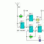
The following diagram is a more advanced version. Its difference from the previous scheme is that in addition to the audible detection alarm, it also has a light indication. This option is also built on the K561LA7 chip.
A detector module is formed on the DD1.1 element, a sound indicator with a piezo emitter is built on the DD1.3 and DD1.4 elements, and a light indication unit is built on the DD1.2 element and the HL1 LED. The circuit is simple and does not need adjustment, and in the case of an error-free assembly, it starts working immediately.
During apartment renovations, especially in older houses, a wiring diagram is required. Otherwise, when drilling holes or chasing, you can damage hidden wires that are energized.
Important! Whether or not you know where the wiring is located, indoor work should be carried out during a power outage.
To search, a metal detector and hidden wiring are used.
Such a device can be bought at a power tool store. This is a necessary equipment for repair teams. However, if you are just doing repairs in an apartment with an interval of several years, the cost of acquiring it is irrational. The device device is simple. A master who knows how to hold a soldering iron in his hands can make a wiring detector with his own hands. In this case, its value will tend to zero.
How to make a wiring detector yourself?
There are two main concepts:
- The principle of voltage multiplication;
- A radio receiver on a microcircuit that captures an electromagnetic field.
Both designs are easy to manufacture, and are assembled on an affordable element base. If you are fond of electronics, you can pick up radio components in your workshop. Even if you buy them on the radio market, the cost is incomparable with the factory model.
Hidden wiring detector on transistors
Components for crafting:
- A multi-stage voltage multiplier will require ultra-sensitive transistors. BC547 have proven themselves well. These are silicon miniature bipolar triodes, with an n-p-n structure. They have a fairly high gain with a minimum level of interference;
- low power resistors. 1MΩ, 1kΩ and 220Ω. For the first, second and third stages, respectively;
- Indicator LED;
- Batteries or accumulators;
- Frame.
Schematic diagram of the device:

The first stage receives a weak signal from the antenna, shown by the arrow in the diagram. It is an electromagnetic field created by electrical wiring.
Tip: To improve search performance, it is recommended to plug in a low-power, interfering electrical appliance, such as a room fan.
A small current appears on the emitter, which is repeatedly amplified by the second stage. A practically ready signal is fed to the base of the third transistor (cascade). After amplification, an electric current is formed on its emitter, sufficient to light up the LED. The device is powered by 6 volts.
Good afternoon, dear electronics lovers!
I decided to add and fix something in my apartment network. The time has come for chiselling and drilling walls, but during this procedure I always worry about the question, but will we meet with wiring in the wall, especially near the electric meter?
So, a hidden wiring detector is required!
The detector circuit that "didn't take off"
On the Internet, the following scheme was chosen:I decided to add a little creativity and insert the device into an empty bottle of roll-on antiperspirant.

Due to the simplicity of the circuit, I decided not to make a printed circuit board, but mounted everything on the back and belly of the microcircuit. To power the circuit, I decided to use a Li-Ion battery from an old netbook battery and.

The process of assembling and compacting all the contents into the body has begun.


I decided to make the antenna not from copper wire (as recommended), but from a piece of television coaxial cable. I liked the fact that it is hard, but elastic.
Unfortunately, the work of this scheme did not suit me at all. Experimented with antennas of different lengths, from different materials. Didn't get any result. There was no wiring in the walls.
Modified hidden wiring detector circuit

Then I decided to try to add a field effect transistor to the input of the device, like the factory device "Dyatel E-121". After that, I was very pleased with the result. The device turned out to be sensitive, and quite accurate for a homemade product. Plus, it's powered by a battery that charges with any micro-USB smartphone charger.
The device sees approximately 30 - 50 mm in the wall. Much depends on the intensity of the current in the conductor, on the material of the walls, etc. In addition, electricians say that any such device must be adjusted.
I am writing an article, because such a device is a very convenient, useful and easy-to-assemble design that will be useful to any home craftsman.
A few words about details
The scheme is simple.C1 = 0.1 uF (100 nF), ceramic or film. C2 = 150 pF, ceramic. C3 = 4700 pF (4.7 nF), ceramic or film.
C4 = 50...1000uF x 16V.
All resistors from 0.125 W and above.
Chip K561LA7(4 logical elements "2I-NOT") can be replaced by imported 4011.
There is a special high-resistance resistor R1 in the circuit. I put 100 MΩ. There was no such denomination on the radio market, so I had to make a small "button accordion" of resistors. I do not recommend setting the nominal value less - the sensitivity will decrease.
As a sound emitter, any piezoceramic emitter such as ZP-3, ZP-1, etc. can be used.
For transistor KP103 the most likely replacement for KP303 when switching on (it is with an n-type channel).
KP103 (p-channel) = 2N3329, J174, J175, J176, J177, MMBF5460.
KP303 (n-channel) = 2N3823, J210, J211, J212, MMBF4392.
How they will work in this scheme - you need to experiment, check.
When performing construction work, it often becomes necessary to check the wall for the presence of wiring in it. To conduct a search, you will need a detector that reacts to the metal. You can purchase this device in the factory version or make a do-it-yourself hidden wiring finder. This article will discuss the nuances of the internal structure of the detectors, as well as methods for their manufacture.
Schemes of factory detectors
There are several types of factory-made detectors:
- Electrostatic. The advantages of such a device are the simplicity of the internal structure and the ability to find metal objects at a considerable distance. The disadvantage of the detector is that it can search only in a dry environment. Otherwise, there will be false positives. In addition, only those wires that are energized can be detected.
- Electromagnetic. The advantages are simple circuit and high-precision wire detection. The only drawback, but significant: in addition to voltage, you need a fairly powerful load - at least 1 kilowatt.
- Metal detector. Such a device is a standard metal detector. The main plus is that there is no need for tension. Disadvantages: detects any metal (not just wiring), and is also structurally complex.
The simplest schemes of homemade devices
There are several schemes of such devices.
With sound indication
You can make a simple do-it-yourself hidden wiring detector based on resistor R1. This resistor protects the circuit from induced voltage. Moreover, even if you install it, it most likely will not affect the operation of the device.
 Hidden wiring detector circuit with sound indication
 A copper conductor with a length of 5 to 15 centimeters is used as an antenna. When wiring is detected, a specific crackle is emitted. The piezoelectric element is connected according to the principle of a bridge circuit, which allows you to control the volume level.
Sound indication in combination with light
This circuit is also simple - you only need one chip.
 Hidden wiring finder circuit on a microcircuit
 Features of the circuit: the value of the resistor R1 must be equal to or greater than 50 MΩ. The LED is used without resistance limitation, since the microcircuit performs this task on its own.
On a field effect transistor (first circuit)
The transistors of this group are extremely responsive to the electric field. This feature is used in the diagram below.
 Field-effect transistor wiring finder circuit
 From the figure, you can understand that the device is very simple, you can make it yourself, without using any special tools. The supply voltage indicator is from 3 to 5 V. The current is so small that the detector is able to function for 5-6 hours without shutting down. The antenna coil is fixed with a 0.3-0.5 mm wire on the core, which, in turn, has a diameter of 3 mm. The number of turns depends on the wire itself: 20 turns for a wire of 0.3 mm and 50 turns for a wire of 0.5 mm. The antenna can function both with a frame and without it.
On a field effect transistor (second circuit)
Another option for making a do-it-yourself hidden wiring detector on a field-effect transistor is to use the KP103 chip. This field worker is characterized by high sensitivity. If its gate is in close proximity to the wiring, the resistance is reduced, which leads to the opening of other transistors. After that, the LED starts to glow.
Note! Polevik KP103 can be used with any letter, as well as the light diode AL307. The fact is that bipolar transistors with such conductivity have low power, and the transfer coefficient must be significant. Therefore, instead of KT203, it is recommended to choose KT361.
The device is small in size - the assembly can be carried out even in the housing from the marker. The antenna is pulled through the hole in the marker. The length of the antenna is from 5 to 10 centimeters. However, if the wiring is not too deep in the wall (no deeper than 10 centimeters), you can get by with the leg length of the field-effect transistor.
 Hidden wiring detector circuit on transistor KP103
 The KP103 transistor is installed horizontally, and the gate must be bent so that it is located directly above the transistor case.
metal detector
 Schematic diagram of a metal detector
 The metal detector circuit looks like this:
- frequency generator (100 kHz) - VT1;
- detector - VT2;
- indication - VT3, VT4.
Generator coils are wound on a ferrite core. Rod diameter - 8 millimeters. The number of turns on the first coil is 120, on the second coil - 45. The wire is selected PEVTL 0.35.
Adjustment of the metal detector must be carried out away from metal products. The tuning is performed by trimmers R3 and R5 in such a way that the generation practically disappears (uneven glow of the diode and low brightness). Next, R3 is tuned in order to fade the emitter.
The next step is to adjust the sensitivity. This is done with a piece of metal (you can use a coin) and a pair of resistors. Moreover, it is recommended to repeat the sensitivity setting periodically. To optimize the process, make it more convenient, regulators can be built into the body of the metal detector.
The tuned device turns on when the antenna is near the metal - the light diode starts flashing.
Wiring indicator without batteries
This detector uses the mains directly as a power source. Such a scheme is possible through the use of a high-capacity capacitor (indicated in the diagram as C1). The capacitor is charged from the network. In a charged state, the capacitor transmits a voltage of 6-10 V. At the same time, only the brightness of the light diode depends on the voltage, but this indicator does not affect the sensitivity of the device.
 Schematic diagram of a hidden wire finder without batteries
 Wiring detector on the microcontroller
 The diagram above shows a hidden wire detector built on the PIC12F629 microcontroller. The operation of the device is based on responsiveness to a magnetic field. This field is formed by current flowing through a conductor located in the wall.
In the circuit, you can use an LED lamp or a piezo emitter. When a magnetic field is detected, a lamp lights up or a piezo emitter starts to crackle, depending on the type of indication preferred.
The advantage of the device is its ability to respond only to a frequency of 50 Hz, which is the frequency of alternating current. Thus, false searcher responses are excluded, since the device will not respond to other frequencies.
Dual element indicator
 Schematic diagram of a two-element detector
 In this case, you need a microcircuit and a light diode. As a microcircuit, you can choose DD1, and it is recommended to take the LED HL1. The task is to connect the leads in such a way as to create three inverters in a circuit. As a result, the device will amplify the currents that are supplied to the device from the AC field in the wiring located in the wall. When wires are detected, the diode lamp starts to glow. When moving away from the wall or breaking the chain, the lamp goes out.
There are two versions of the scheme:
- Connection of conclusions: the third with the eighth, the second with the tenth, the fourth with the seventh and ninth, the first with the fifth, the eleventh with the fourteenth.
- Connection of conclusions: the third with the eighth, the tenth with the thirteenth, the first with the fifth and twelfth, the second with the eleventh and fourteenth, the fourth with the seventh and ninth.
Industrial circuits of professional detectors
You can assemble at home and a professional-level device. However, such equipment has a rather complex scheme, and it will take a lot of effort to manufacture it. Below are two schemes to choose from: the first refers to an industrial device, the second - to a home-made device "Woodpecker".
 Scheme of an industrial hidden wiring signaling device
  Scheme of a home-made wiring determinant "Woodpecker"
 It is also possible to manufacture a YADITE 8848 type device. Two variants of such a device are shown below.
 Schematic diagram of the detector on the TC4069UBP
  Wiring Finder Schematic on 74HC14AP
 Checking homemade wiring finders
Before using a homemade device, it is recommended to test its performance. Checking will show the correct assembly.
The test is performed as follows:
- We find a site in which there is definitely a hidden wiring. For example, it is guaranteed that we can talk about the presence of wires in the wall going to switches and sockets.
- We check the selected area. To do this, we bring the device to the wall and observe the indication.
- If the signal is received only at the cable passage, the device is working properly and can be used.
- If the signal appears, then disappears in different directions, then the device is faulty.
Advice! Before starting the test, the wiring must receive the maximum load. To ensure such a load, we connect as many electrical appliances as possible to the network. As a result, the magnetic and electric fields are amplified, to which the devices respond.
So, it is not necessary to purchase a wiring detector in a store. This device can be made at home if you follow the above schemes.
When you plan to hang a picture or a wall clock, how do you choose the right place to hang it? You are probably thinking about how the picture will fit into the interior of the room, on which wall it is better to place it and how. But do you think that not everywhere you can hammer a nail in the wall and drill a hole for the dowel? It's not about what material your walls are made of, as there is a more significant circumstance - this is electrical wiring. In order not to damage the wires immured in the wall, you need to know where they are laid.
There are several ways to find out roughly where the electrical cable runs: you should look into the technical documentation of the apartment and look at the wiring diagram of the electrical network, if there is none, then pay attention to the location of the junction boxes from them wires go to sockets and switches. As a rule, sensible electricians lay the cable at a right angle.
It’s good when you changed the old electrical wiring and are aware of its placement, but what if the previous owner of the house was a mountain self-taught electrician and did not follow the elementary rules for wiring? There are cases when, in order to save money, the wires are bred along the shortest path: from the boxes diagonally and horizontally - in this case, special tools for detecting it cannot be dispensed with.
In stores and radio markets they sell special devices called "Flushed Wiring Detector". They are cheap (low class) and expensive (high class). A low-class device determines the source of electromagnetic radiation - these are live wires and electrical appliances. High-end detectors are more accurate and functional: their work is aimed at detecting wires directly, even those that are without voltage.
For home use, a simple detector that you can make yourself will be enough for us. As you understand, the simple circuit we have assembled refers to budget devices - therefore, we will not succeed in a high-end device. But homemade will help you not to get into trouble when doing construction work and at the moment when you decide to decorate your room with a beautiful picture or wall clock. In order to assemble a concealed wiring detector in haste, we need three non-deficient radio components, which we can easily find.
The main element is the Soviet K561LA7 microcircuit (the detector itself is assembled on it). The microcircuit is sensitive to electromagnetic and static fields emanating from conductors of electrical energy and electronic devices. The microcircuit is protected from an increased electrostatic field by a resistor, which is an intermediate element between the antenna and the IC. The sensitivity of the detector determines the length of the antenna. As an antenna, you can use a single-core copper wire with a length of 5 to 15 centimeters. For stable operation and not at the expense of sensitivity, I chose a length equal to 8 centimeters. There is one caveat: if the antenna length exceeds the threshold of 10 centimeters, there is a risk that the microcircuit will go into self-excitation mode. In this case, the detector may not work correctly. Also, when the electrical cable is buried deep in the plaster, the detector may not make a single sound.
If a homemade detector does not work correctly, it is worth experimenting with a long copper antenna. It can be either less or more than the recommended length. When the detector stops responding to anything except the electrical cable, then you have found the right length (if you have not chosen the correct length, then the detector can respond to a simple touch of a person or any objects).


We figured out the nuances, now we turn to the third element of the circuit - this is a piezoelectric element. A piezoelectric emitter (piezoelectric element) is necessary for the perception by ear of capturing an electromagnetic field, when this happens, the emitter emits a crack. A piezoelectric element or, in a simple way, a “tweeter” can be obtained from a non-working Tetris, Tamagotchi or watch. You can also replace the tweeter with a milliammeter from an old tape recorder. The milliammeter by the deviation of the arrow will show the level of the radiated field. If you decide to use a piezo element and a milliammeter, then the crackling sound emitted will be a little quieter.
The circuit is powered by a voltage of 9 volts, so we need a Krona battery. The assembly of the circuit can be carried out on a printed circuit board or by surface mounting. Surface mounting for a simple 5-element circuit would be preferable. Take the cardboard, attach the chip with the legs down and pierce holes under each leg with a needle (14 pieces, 7 on each side). After preparing the place for the microcircuit, insert the legs into the holes made and bend them. So we will securely fix the integrated circuit on cardboard and facilitate the work when soldering wires.


In order not to overheat the chip, you should use a low-power soldering iron. A 25-watt soldering iron is usually used for soldering radio components. Let's start assembling the detector according to the scheme given in the article. If you have followed all the above recommendations, then the circuit should work instantly without any adjustment. Now we find a suitable case and embed the circuit in it. Make holes for the tweeter and glue the piezo emitter on the back side. In order for the detector not to work constantly, solder a toggle switch into the power circuit break. Reloading the detector by turning the toggle switch on and off will help you bring the microcircuit out of self-excitation mode.


By tradition, I want to finish the article with a video report on the work done. The video tested the operation of a homemade and factory hidden wiring detector. As it turned out, the made detector more accurately showed the location of the electric cable than a cheap purchased detector.
Having assembled a detector to search for hidden wiring, you should not be afraid of damage to the electrical network of your home, because you can always find an electrical cable. Good luck in mastering simple circuits in radio electronics. If you have any questions, please contact me in the comments - we will figure it out!
About the author:
Greetings, dear readers! My name is Max. I am convinced that almost everything can be done at home with your own hands, I am sure that everyone can do it! In my free time, I like to craft and create something new for myself and my loved ones. You will learn about this and much more in my articles!
