This transmitter was made while still in school. I honestly don’t remember which book the diagram was from, but the book was from the 60s. And the scheme was on some kind of "GU-shke". But I converted it to 6P14P lamps. With proper assembly, it almost does not need to be configured. And this type of modulation gives a wide field for experiments. Including a wide range of frequencies of its work. In this case, the entire range of VHF and FM is covered.
Schematic diagram
- Power transformer from a lamp receiver, 200-250 volts. A rectifier can be made on the 226's.
- Dr1 is also from a receiver or TV of the 3rd class, not W-shaped iron is wound. 2000 turns of PEL-0.18 wire.
- Dr2 is wound on a plastic tube, a cylinder and contains 40 turns of PEL 0.2 wire.
- DR3 is the same as DR2 but with a tap from the middle.
- L1 - two turns of PEL-1 wire, 0.8-1 mm in diameter, and coil L2 one turn of the same diameter.
And, in fact, the adjustment of the transmitter - it comes down to the convergence or distance of these coils. But it's better when one enters the other. The antenna was made by the transmitter. And I didn't measure the distance. About a few kilometers, I think about five.
This FM transmitter is based on a varicap oscillator and a two-stage power amplifier. With a good antenna - for example, a dipole located high enough, the transmitter has a very good range - about a kilometer, the maximum range is up to 5 km. The circuit diagram is not at all complicated - with a little experience, you can assemble it with your own hands in an evening. Thumbnail shown.
Schematic diagram of a powerful broadcast FM radio transmitter
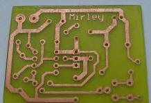
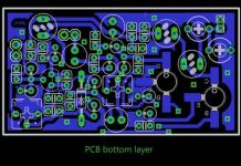
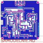
Transmitter PCB Drawings


Specifications of the radio transmitter
- - Power: 12-14V, 100mA
- - RF power: 400 MW
- - Impedance: 50-75 ohm
- - Frequency range: 87.5-108MHz
- - Modulation: wideband FM
To adjust for maximum radiation, connect a 6 V / 0.1 A light bulb instead of an antenna. First of all use the resistor R1 to tune to the desired frequency, you can adjust the inductance of the coil L1 if necessary. Then, use trimmer capacitors C18 and C19 to achieve maximum power (bright lamp light). And only then you can connect the antenna and the audio signal to the input of the radio transmitter. Adjust R2 so that the sound is loud enough and of good quality, like on other FM radio stations.


Varicaps can be replaced with domestic ones, which are installed in the SK-V TV modules. For example KV109 or KV104. Transistor BFR96 - KT610. The rest - KT368. A further increase in range is possible with an additional .
 An FM radio receiver assembled on a single transistor using a regenerative circuit. An FM radio receiver assembled on a single transistor using a regenerative circuit. |
The described generator can be used as a master in a VHF broadcast transmitter, or work directly on the antenna. It has good repeatability and is reliable in operation, which allows us to recommend it to novice radio amateurs as the first RF design with serious power.
Options:
Guaranteed frequency range - 65-108 MHz, when using VHF and microwave lamps can reach 400 MHz
Output power - depends on the type of parts used.
Modulation - frequency
Deviation + - 75 KHz.
Books no more than 5%
Frequency drift is not more than 10 to the -5 degree.
With proper manufacture, short-term instability can be better than 10 kHz at 108 MHz in 1 minute
after warming up 30 minutes.
Brief description of the work.
L1C3 form an oscillatory circuit, tuned to the desired frequency. The paws are included in antiphase, forming a symmetrical push-pull circuit. Capacitors C1C2 create the feedback necessary for self-excitation. The chains R1L3 and R2L4 create an automatic offset - gridlick. Through C5 and C6, varicaps with a strapping are connected - in fact, a modulator. L6C7 and L7C8 prevent RF from flowing to the ULF output connected to Umod. L5 is the coupling coil from which the output signal is taken. C4 is used to adjust the optimal communication with the circuit.
Details.
Any triodes or tetrodes of sound and higher ranges are suitable as lamps. It is advisable to choose lamps with the same characteristics, for example, from the same batch. But the best results are given by special dual generator tetrodes - with them the maximum efficiency, the least amount of out-of-band radiation and the uniformity of resource development are obtained.
List of tested lamps:
6N3P
6N23P
6P14P
6P15P
6P3S
6P6S
GU29
GU32
GU50
GI30B
We immediately warn against attempts to use line-scan lamps for TVs, for example, 6P45S. These lamps do not tolerate work in this design quite well, and therefore are not recommended.
Mode options depending on the type of lamps:
2x6P14P
Ua = 300 V
Rout up to 15 W
2x6P3S
Ua = 400 V
Rout up to 40 W
GI30B
Ua = 800 V
Rout up to 50 W
Capacitor C3 is a differential butterfly type with a maximum capacitance of 15-25 pF, or pulled from a tube receiver. Trimmers of the KPV-M type are about 3 ... 15 pF. C7 C8 blocking, selected depending on the output resistance of the ULF. Throttles - homemade. A 0.5W VZR or BC resistor with flat contacts is taken. The resistive coating is cleaned with sandpaper, then the PELSHO wire (this is the blue shaggy one) is wound until it is filled. The ends are soldered to the legs. This inductor also serves as a fusible link in case of a short circuit. We strongly recommend varicaps KV109A - they have an acceptable quality factor. You can find them in SKD and SLE TVs of 3-4 generations. Approximate value R1, R2 10KOm, R3, R4 1Kom. The parameters of the L1 circuit depend on the broadcast range and the interelectrode capacitances of the lamps. Winding is carried out on a mandrel 1-2 cm with PEL wire with a diameter of 1-2 mm with a step of 2-3 mm. The approximate number of turns is 5. The coupling coil L5 is wound over L1 with a gap of 5-10 mm to exclude their electrical contact and is suspended in space on contact C4 and the connector. Don't forget that tetrodes also need a positive grid bias. Provide for this an appropriate voltage source, or lower the anode resistor to the desired value with a resistive divider. And of course, the lamps require heat.
The design can be anything. It is only necessary to comply with the requirements for high-power RF structures. The chassis must be mechanically strong and conduct electricity well. It can be a box made of metal or foil fiberglass. Make the installation with rigid, as short wires as possible. Perform grounding in the shortest way with the parts themselves, avoiding unnecessary wires.
Tuning requires a voltmeter, a field strength indicator, an incandescent lamp with a resistance of 25-100 ohms and a receiver for the desired range.
Before switching on, C3 should be set to the middle position, C4, C5, C6 to the minimum position, and C1, C2 to the maximum position.
It should be noted that the generator works well even with one lamp. It's just that the circuit becomes asymmetric, as a result of which the level of even harmonics slightly increases. Therefore, if there is no generation, look for an error in the installation and check the health of the elements.
Radio transmitting devices (Fig. 13.1 - 13.5) can be obtained by simply combining an amplifier (or generator) of a low frequency (VLF, LLF) and a high frequency generator (HHF). Block diagram of an amplitude modulated (AM) transmitter,…….
The radio control unit receiver with 256 channels is one of two receivers designed to work with the radio control unit with 20 million codes. The receiver of the radio control unit is for the device selected from…….
This portable UHF radio is of exceptional quality and reliability. The use of reliable and adjusted modules is the key to success and satisfaction. In addition, the modules used operate in the FM band, which ensures the quality…….
Recently, “toy” radio stations manufactured in China, the so-called “walkie-talkies”, have appeared on sale. They are simple and have relatively good performance. The author's radio station “CB STYLE ORIGINAL” NS-881…….
In order for the transmitter to have a high efficiency, and the receiver to have a large stable gain, some specific requirements must be taken into account when designing VHF equipment. Loop coils should be made of copper…….
Many beginners (and not only) radio amateurs, sooner or later become interested in the topic of transmitters. Indeed, the construction of VHF transmitters for the 88-108 MHz band is a fascinating and useful topic. Radio microphones, bugs and other devices can be assembled on the basis of FM radio transmitters. There are many schemes for such devices, but finding a simple, powerful and at the same time stable generator with UHF is a problem. After a long search, the choice fell on the following scheme.
The block was built on the basis of known schemes, but several modifications were added. The system works almost perfectly, the range is large, the sound quality is good. BF240 transistors are used, but others can be installed here, from the list below. Frequency change is carried out using a potentiometer.
List of semiconductor elements for assembly
- BB105G
- BB104G
- BF240 (BF199, BF195, BF183,184,185)
- 2n2369
- 1n4007
There is only one, very simple coil to wind. Many people have problems with this, but winding 5 turns of 1 mm wire on a 5 mm mandrel will be within the power of everyone.

As for shielding - tin does its job. When tests were done without a screen, the frequency swam and reacted to the approach of the hand. After applying the screening, the circuit worked stably and no longer reacts to the approach of the hand.

Capacitors and power chokes can be useful to prevent self-excitation. During the tests, this did not arise - therefore, the denouement was not set.

In addition to the output power level of the radio transmitter, much depends on the antenna. You can even receive a signal from it at a distance of up to 1 km, if you put a long pin a couple of meters.
