It is a simple boost converter built on the NE555 m / s, which performs the function of a pulse generator here. The output voltage can vary between 110-220V (adjustable with a potentiometer).
Application area
The converter is ideal for powering Nixie clock or low-power clock tubes or headphone amplifiers, replacing the classic high-voltage power supply on transformers. The purpose of this device was to design a vacuum indicator clock in which the circuit operates as a high voltage power source. The converter is powered by 9 V and consumes a current of about 120 mA (at a 10 mA load).
The principle of operation of the circuit
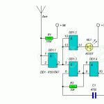
As you can see, this is a standard step-up voltage converter. The output frequency of the U1 (NE555) chip is determined by the values of the elements R1 (56k), R3 (10k), C2 (2.2 nF), and is about 45 kHz. The output from the generator directly controls the mosfet transistor T1, which switches the current flowing through the coil L1. During normal operation, the coil L1 periodically stores and releases energy, increasing the output voltage.
555 inverter circuit
When the transistor T1 (IRF740) opens and supplies power to the coil L1 (100 μH) (the current flows from the power source to ground - this is the first stage. In the second stage, when the transistor is turned off, the current through the coil, in accordance with the switching law, causes an increase in voltage at the anode of diode D1 (BA159) until it is polarized in the direction of conduction.The coil is discharged into capacitor C4 (2.2uF).Thus, the voltage at C4 rises until the voltage at the output of divider R5 (220k), P1 (1k) and R6 470R will not rise to a value of about 0.7 V. This will turn on transistor T2 (BC547) and turn off the generator 555. When the output voltage drops, transistor T2 will be closed and the generator turns on again. So the output voltage of the converter is regulated in magnitude.
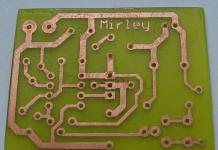
 Finished board for soldering
 Capacitor C1 (470uF) filters the supply voltage of the circuit. The output voltage is adjusted using potentiometer P1.
Assembling a transformerless converter
 Assembled converter 9-150 volts
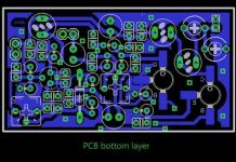
 The converter can be soldered on the printed circuit board. Drawing PDF of the board, including mirror image and the location of parts - . Installation is simple and the soldering of elements is arbitrary. Under the U1 chip, it makes sense to use a socket. The device should be powered by 9V.
To use the power transformer available in stocks, it is necessary to know its key characteristics as accurately as possible. With the solution of this problem, there are almost never any difficulties if the marking is preserved on the product. The required parameters can be easily found on the Web by simply entering the letters and numbers engraved on the transformer into the search bar.
However, quite often there is no marking - the inscriptions are rubbed off, destroyed by corrosion, and so on. On many modern products (especially cheap ones), marking is not provided at all. Throwing away the transformer in such cases, of course, is not worth it. After all, its price in the market can be quite decent.
The most important parameters of power transformers
What do you need to know about the transformer in order to correctly and, most importantly, safely use it for your own purposes? Most often, this is the repair of any household appliances or the manufacture of their own crafts that are powered by low voltage. And you need to know the following about the transformer lying in front of us:
All these characteristics are quite realistic to calculate even when there is absolutely no information about the brand and model of the power transformer.
To do the job, you will need the simplest tools and supplies:
- multimeter with ohmmeter and voltmeter functions;
- soldering iron;
- electrical tape or heat shrink tubing;
- mains plug with wire;
- a pair of ordinary wires;
- incandescent lamp;
- calipers;
- calculator.

You will also need some kind of wire stripping tool and a minimal soldering kit - solder and rosin.
Definition of primary and secondary windings
The primary winding of the step-down transformer is designed to supply mains power. That is, it is to it that you need to connect 230 volts, which are in a regular household outlet. In the simplest versions, the primary winding can have only two outputs. However, there are also those in which there are, for example, four conclusions. This means that the product is designed to work from both 230 V and 110 V. We will consider a simpler option.
So, how to determine the conclusions of the primary winding of the transformer? To solve this problem, you need a multimeter with an ohmmeter function. With it, you need to measure the resistance between all available outputs. Where it will be the most, there is the primary winding. It is advisable to immediately mark the findings found, for example, with a marker. 
The primary winding can be determined in another way. To do this, the wound wire inside the transformer must be clearly visible. In modern versions, this is most often the case. In older products, the insides may be filled with paint, which excludes the use of the described method. The winding with the smaller wire diameter is visually highlighted. She is primary. It needs to be supplied with mains power.
It remains to calculate the secondary winding, from which the reduced voltage is removed. Many have already guessed how to do it. Firstly, the resistance of the secondary winding will be much less than that of the primary. Secondly, the diameter of the wire with which it is wound will be larger. 
The task becomes a little more complicated if the transformer has several windings. This option is especially scary for beginners. However, the method of their identification is also very simple, and is similar to that described above. First of all, you need to find the primary winding. Her resistance will be many times greater than that of the rest.
At the end of the topic on transformer windings, it is worth saying a few words about why the resistance of the primary winding is greater than that of the secondary, and with the wire diameter everything is exactly the opposite. This will help beginners to understand the issue in more detail, which is very important when working with high voltage.
A mains voltage of 220 V is supplied to the primary winding of the transformer. This means that with a power of, for example, 50 W, a current of about 0.2 A will flow through it (we divide the power by voltage). Accordingly, a large cross section of the wire is not needed here. This is, of course, a very simplified explanation, but for beginners (and the solution of the problem posed above), this will be enough.
In the secondary winding, currents flow more significant. Let's take the most common transformer that delivers 12 V. With the same power of 50 W, the current flowing through the secondary winding will be about 4 A. This is already quite a large value, because the conductor through which such a current will pass must be thicker. Accordingly, the larger the cross section of the wire, the less resistance it will have.
Using this theory and a simple ohmmeter, you can easily calculate where the winding of a step-down transformer without marking is.
Determining the voltage of the secondary winding
The next step in identifying the "nameless" transformer will be to determine the voltage on its secondary winding. This will determine whether the product is suitable for our purposes. For example, you are assembling a 24 V power supply, and the transformer only outputs 12 V. Accordingly, you will have to look for another option. 
To determine the voltage that can be removed from the secondary winding, the transformer will have to be supplied with mains power. This is already quite a dangerous operation. By negligence or ignorance, you can get a strong electric shock, burn yourself, damage the wiring in the house, or burn the transformer itself. Therefore, it will not be superfluous to stock up on a few recommendations regarding safety precautions.
Firstly, when testing, the transformer should be connected to the network through an incandescent lamp. It is connected in series, in the gap of one of the wires going to the plug. The light bulb will serve as a fuse in case you do something wrong, or if the transformer under study is faulty (short-circuited, burned out, wet, and so on). If it glows, then something went wrong. There is a short circuit in the transformer, so it is better to pull the plug out of the socket immediately. If the lamp does not glow, does not stink or smoke, work can be continued.
Secondly, all connections between the outlets and the plug must be carefully insulated. Do not neglect this recommendation. You will not even notice how, considering the readings of the multimeter, for example, you will undertake to correct twisted wires, you will get a pretty electric shock. This is dangerous not only for health, but also for life. For insulation, use electrical tape or heat shrink tubing of the appropriate diameter.
Now the process itself. A conventional plug with wires is soldered to the terminals of the primary winding. As stated above, an incandescent lamp is added to the circuit. All connections are isolated. A multimeter in voltmeter mode is connected to the terminals of the secondary winding. Please note that it is turned on for measuring AC voltage. Beginners often make a mistake here. By setting the multimeter pen to measure DC voltage, you will not burn anything, however, you will not get any sane and useful readings on the display. 
Now you can insert the plug into the socket. If everything is in working condition, then the device will show you the reduced voltage generated by the transformer. Similarly, you can measure the voltage on other windings, if there are several. 
Simple ways to calculate the power of a power transformer
With the power of a step-down transformer, things are a little more complicated, but there are still some simple techniques. The most accessible way to determine this characteristic is to measure the diameter of the wire in the secondary winding. To do this, you will need a caliper, a calculator and the information below.
First, the diameter of the wire is measured. For example, take a value of 1.5 mm. Now you need to calculate the cross section of the wire. To do this, you need to square half the diameter (radius) and multiply by the number "pi". For our example, the cross section will be about 1.76 square millimeters.
Further, for the calculation, you will need the generally accepted value of current density per square millimeter of conductor. For household step-down transformers, this is 2.5 amperes per millimeter square. Accordingly, a current of about 4.3 A can “painlessly” flow through the second winding of our sample.
Now we take the previously calculated voltage of the secondary winding, and multiply it by the resulting current. As a result, we get the approximate value of the power of our transformer. At 12 V and 4.3 A, this parameter will be around 50 watts.
The power of the "nameless" transformer can be determined in several other ways, however, they are more complex. Those who wish can find information about them on the Web. Power is recognized by the cross section of the transformer windows, using calculation programs, as well as by the nominal operating temperature. 
Conclusion
From the foregoing, we can conclude that determining the characteristics of a transformer without marking is a fairly simple task. The main thing is to follow safety rules and be extremely careful when working with high voltage.
You may like:
- Crochet knitted rugs: interesting models, patterns and ...
- Ideas for pillows from old sweaters... I would never...
- Tips that will be useful for both beginners and ...
A transformer is a device for transferring energy from one circuit to another by means of electrical induction. It is intended for converting currents and voltages, for galvanic separation of electrical circuits, for converting resistances in magnitude and for other purposes.
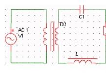
A transformer may consist of two or more windings. We will consider a transformer of two separated windings without a ferromagnetic core (air transformer), the circuit of which is shown in fig. 5.12.
The winding with 1-1 'terminals connected to the power supply is primary, the winding to which the load resistance is connected is secondary. Primary resistance ![]() , the resistance of the secondary
, the resistance of the secondary ![]() .
.
 The transformer equations with the accepted polarity of the coils and the direction of the currents have the form:
 - for primary winding
For secondary winding
Transformer input impedance
We denote the active resistance of the secondary circuit
then the equations can be rewritten
 (5.22)
Transformer input impedance. Given that  and substituting into the first equation (5.21), we get that
Thus, the input resistance of the transformer from the side of the primary terminals consists of two terms: - the resistance of the primary winding without taking into account the mutual inductance, which appears due to the phenomenon of mutual inductance. The resistance is, as it were, added (introduced) from the secondary coil and therefore is called the introduced resistance.
Input impedance of an ideal transformer.
An ideal transformer (theoretical concept) is a transformer in which the conditions
 (5.24)
At the same time, with a certain error, such conditions can be met in a transformer with a core with high magnetic permeability, on which wires with low active resistance are wound.
The input impedance of this transformer
 (5.25)
Therefore, an ideal transformer connected between the load and the power source changes the load resistance in proportion to the square of the transformation ratio n.
 The ability of a transformer to convert resistance values is widely used in various fields of electrical engineering, communications, radio engineering, automation, and above all for the purpose of matching source and load resistances.
Transformer equivalent circuit
 A diagram of a two-winding transformer without a ferromagnetic core can be shown as shown in Fig. 5.14. The current distribution in it is the same as in the circuit in Fig. 5.12 without a common point between the windings.
 Let's make in the scheme on fig. 5.14 decoupling of inductive connections. In this case, we obtain the equivalent circuit of the transformer (Fig. 5.15), in which there are no magnetic connections.

Energy processes in inductively coupled coils
Air transformer differential equations (Fig. 5.15):
 (5.25)
Multiply the first equation by and the second by:
 (5.26)
Adding these equations, we get the total instantaneous power that is consumed from the source and consumed in the primary and secondary windings of the transformer and in the load
 (5.27)
where is the instantaneous power at the load, ;
- instantaneous power consumed for heat in the transformer windings, ![]() ;
;
is the energy of the magnetic field of the transformer windings,  .
.
Three-phase generators.
A three-phase circuit (system) is understood as a combination of a three-phase source (generator), load and connecting wires.
It is known that when a conductor rotates in a uniform magnetic field, an EMF is induced in it
![]() . (1.1)
. (1.1)
 We fix three identical coils (windings) rigidly on the same axis, displaced relative to each other in space by (120 °) and begin to rotate them in a uniform magnetic field with an angular velocity w (Fig. 1.1).
In this case, coil A will be induced
The same EMF values will occur in coils B and C, but, respectively, 120° and 240° after the start of rotation, i.e.
 (1.3)
(1.3)
A set of three coils (windings) rotating on the same axis with an angular velocity w, in which EMFs are induced, equal in magnitude and shifted from each other by an angle of 120 °, is called a symmetrical three-phase generator. Each generator coil is a generator phase. In the generator in Fig. 1.1 phase B "follows" phase A, phase C follows phase B. Such a phase sequence is called direct sequence. When changing the direction of rotation of the generator, the phase sequence will be reversed. A direct sequence based on relations (1.2, 1.3) corresponds to the vector diagram of the EMF shown in fig. 1.2, a, for the inverse - the vector diagram of the EMF in fig. 1.2, b.
In the future, all reasoning on the calculation of three-phase circuits will concern only three-phase systems with a direct sequence of generator emfs.
The diagram of change of instantaneous values of EMF at y = 90° is shown in fig. 1.3. At every instant, the algebraic sum of the EMF is zero.
The extreme points of the coils (windings) are called the end and the beginning. The beginnings of the coils are designated A, B, C, the ends, respectively, X, Y, Z (Fig. 1.4, a).
The phase windings of a three-phase generator can be depicted as sources of EMF (Fig. 1.4, b).

There are quite a few electronic devices that require about 200 volts of direct voltage - these can be various meters, low-power lamp technology, pulsed chargers for smartphones and mobile phones. And the problem becomes even more complicated when the power is not from a 220-volt outlet, but from a battery or car battery. In order not to have to look for a bulky and rather expensive transformer at the present time, the developers created a simple DC-DC switching regulator that can convert 12 volts to high.


The module is based on the MAX1771, which is a typical DC-DC boost inverter. This chip operates at switching frequencies up to 300 kHz, which allows the use of miniature surface mount components - SMD. The converter accepts input voltages ranging from 2 to 16 volts, and the output voltage is adjusted to approximately 200 volts using external resistors and potentiometers. This is enough to power, for example, a circuit assembled on lamps.

The MAX1771 chip drives a powerful N-channel MOSFET, and with the help of an inductor and fast diodes, a high-voltage conversion is performed. The circuit is capable of handling currents up to 2 amps at the input, or with 24 watts of output power. A simple calculation shows that this is about 0.1 A at a given voltage. Efficiency is about 90%.
The myth of tube amplifiers.
The tube amplifier cannot be powered directly from the mains.
Therefore, a converting transformer 220 Volt / ... 220 Volt is installed! Of course, in the secondary winding there are more than 220 and less than 220, depending on the choice of lamps and their mode. But, you must admit, quite often tube amplifiers are powered from a rectified 220 V (i.e. constant 295 ... 305 V - depending on how much one has in the outlet). So, why in Hi-End equipment, positioning the principle of “as few details as possible in the sound path” this “extra” element ?!
Imagine for a moment (save the counter-arguments for now) what advantages such a tube amplifier would have. So, the cost of the device itself will probably decrease (estimate by how much, if the amplifier, let's say medium power and class “A”). Weight. Significantly facilitate such a mind. There will be more free space - definitely. No power transformer - no interference! The argument is very impressive. Those who have tube amplifiers have the property of “phoning” (even if only a little), they will agree that without a “background” it would be better. More comfortable, so to speak. There will be nothing to buzz and warm up. What else? Then the most “lethal” argument: your amplifier will not depend on the power reserve of this very power transformer. The entire nearest substation is at your disposal! The dynamics of the sound will be the maximum possible for the given scheme of your amplifier.
A minute has passed. Minuses. Or rather, one minus, the only one, by the way. But, minus with a capital letter - “Phase” !! The most dangerous thing for human health and the well-being of electronics. However, everyone uses computers and laptops. And they have switching power supplies, with the notorious direct power supply from the mains. So there is a “galvanic isolation”, you say. And who, sorry, prevents you from putting this very “galvanic isolation” into your tube amplifier. In addition, in any tube amplifier it is partially implemented. Do not believe?! Remember the output (sound) transformer. How many volts are there in the primary winding? On average, 300 volts, or even more. But no one shouts “No!”. Almost all owners of tube amplifiers install and successfully use it. I hope it’s not worth continuing the logical chain, on the topic “how to make a galvanic isolation of the entire circuit”, and not just along its “output”.
For those who doubt the benefits of “an extra part that introduces additional phase / frequency and other distortions”, I give a working diagram of such an amplifier:
Actually, the circuit is a “bridge” inclusion of two identical amplifiers. A sort of OTL on the contrary. What does it give? Reduced requirements for supply voltage ripple. The overall distortion is reduced, since the amplifiers operating in antiphase compensate not only for supply voltage ripples, but also for their own (introduced by cascades) distortions. And since the output stage is made according to the topology “cascode circuit-SRPP - Shunt Regulated Push Pull (SRPP, cascade with dynamic load), there is no constant component in the output transformer (those notorious 300 volts of anode voltage). There is no magnetization of iron - there are no specific distortions inherent in classical circuits. In any case, it is not necessary to apply special measures to combat this harmful phenomenon. This simplifies the requirements for the output transformer. In addition, such a topology promises better performance. The input (driver) cascade is also made “two-story”. Driver cascades of this type are quite often used in lamp technology. But in the output stage is much less common. The fact is that the output power taken from such a cascade - “cascode” is four times lower than two classically parallel lamps. Therefore, those who are interested in the efficiency of the amplifier, in the first place (for example, manufacturers of household appliances), and quality - in the second, this circuitry will not work by definition. Nevertheless, the maximum output power of this amplifier is quite sufficient to drive even speakers with low sensitivity. And is 8 watts. With acoustic systems with a sensitivity of more than 90 dB / W / m, this is more than enough margin. Let me remind you that “tube Watts” sound a little louder (so to speak) than “transistor” ones.
In order for the signal to arrive in antiphase at the input of the amplifier, the most symmetrical of the existing types of phase inverter is used - a transformer. Its transformation ratio is chosen 1:2+2 under the CD standard (2 V eff.). Thus, the input transformer performs three functions: it is a phase inverter, a matching transformer and performs the function of ... "galvanic isolation". The amplifier input is a balanced line (balanced connection).
The amplifier circuit is placed in a natural wood case, which has a varnish coating. There are no screens. The circuit does not need to adjust modes or any kind of balancing. Selection of pairs of (serviceable) lamps is not required. The driver uses 6H9C lamps. Those who prefer an "analyst-neutral" sound to a more "musical-tube" color can replace these tubes with 6H8C (without changing the resistor values). The sound will acquire “that same tube” tone of sound that most users of musical recordings like. It should be remembered that the gain of 6H8C lamps is two times lower than 6H9C, which will lead to a halving of the output power and will be 4 watts. In the output stage, “tight” 6H13C lamps of the same “octal” series were used. Therefore, it is optimal to start listening to music after 90 minutes (!) After turning on the amplifier. It is after such a period of time that the amplifier begins to “sound_as_it_should”.
The photo shows amplifier No. 5, made according to this scheme. Instead of 6H13S output lamps, 6H5S were used. Output power -7.5 W (8 ohms).
Additional information (winding data of matching transformers and options for using finished transformers as output transformers, etc.) can be found in the Radioconstructor magazine No. 2, 2014, pp. 6-9.
