But it was LED (the LED lights up in response to the wiring). But this time it's a sound wire detector. When a wire is detected, a crackle is emitted, the closer the wire, the more intense the crackle.
Based on the Soviet chip K561LA7. Working on field-effect transistors. This warning is due to the fact that the soldering iron must be grounded before soldering and not more than 60 watts.
The supply voltage of the microcircuit is from 3 to 18 V. So it’s not difficult to choose the power supply. Batteries from phones, krone, etc. will do. which significantly reduces the size of the device.
In my case, this is the battery from the phone.
We need a microcircuit, a resistance of 1 MΩ, a piece of single-core copper wire (8 to 15 cm long - this will be an antenna) a tweeter (you can use an old working earphone) and a power source.
Empty box - I used an outdated USB adapter. And took out all the insides. Just the right size for the battery.


It's not worth paying for something like this.
So I took a small piece of cardboard. Marked out where you need to make holes and pierced with a regular pin.


We bend the ends to the sides so that they do not interfere with soldering.

And here is the simplest scheme for soldering.


We carefully solder everything.

We check the device for operability, if everything works fine, we make a screen (we isolate the microcircuit from interference).
We fill everything well with hot glue.
Then, when the glue dries, wrap the entire scheme with food foil.


We pack everything in a box.
We check.
Drilling a hole for a dowel-screw or a nail in the wall is easy. The main thing is not to stumble upon hidden wiring when perforating and not damage it. A hidden wire detector helps to detect a break and a live electrical cable in the wall. In order not to spend extra money, let's design a simple detector based on the K561LA7 chip, talk about the selection criteria and the advantages of factory devices.
Homemade detector with a piezoelectric element - in simple words about the complex
Flush-wire detectors are divided into low-end and high-end devices. The low-class device is designed to search for electrical appliances and wiring that is energized. The high-class detector has great sensitivity and advanced functionality. Such a device serves to determine the breakage of hidden wiring, detects the location of wires without voltage.
You can make a hidden wiring detector with your own hands from improvised means by purchasing a few small parts. When designing this device, please note that it is suitable for detecting wiring in a live wall. And if you need high-frequency equipment to detect a break and pinpoint the exact location of the cable down to the millimeter, purchase a quality detector in the store.
To assemble the device, you will need the following set of elements:
- chip K561LA7;
- 9 V Krona battery;
- connector, battery connector;
- current limiter (resistor) with a nominal resistance of 1 MΩ;
- sound piezoelectric element;
- single-core copper wire or wire L = 5–15 cm;
- wiring for soldering contacts;
- a wooden ruler, boxes from under the power supply, another home-made design for laying the chain.
Additionally, for work, you will need a low-power soldering iron up to 25 W, so as not to overheat the microcircuit; rosin; solder; wire cutters. Before proceeding with the assembly, let's take a closer look at the main elements. The main part on which the assembly takes place is the Soviet-type K561LA7 microcircuit. It can be found on the radio market or in old stocks. The K561LA7 microcircuit is sensitive to static and electromagnetic fields, which are created by electrical devices and conductors. The current level in the system controls the resistor, which is located between the integrated circuit and the antenna. We use a single-core copper wire as an antenna. The length of this element affects the sensitivity of the device, it is selected experimentally.
When choosing the length of the copper wire, ensure that it reacts only to the electrical cable. This will allow you to pinpoint the exact location of the wiring in the wall.
Another important assembly detail is the piezoelectric element. Capturing an electromagnetic signal, it creates a characteristic crackle that signals the presence of wiring in a given location. It is not necessary to specifically purchase a part, remove the speaker from the old player, toys (Tetris, Tamagotchi, clock, sound machine). Instead of a speaker, you can solder headphones. The sound will be clearer and you won't have to listen to the crackle. As an indicator of hidden wiring, an LED element can be additionally mounted in the device. The circuit is powered by a 9-volt Krona battery.

To make it more convenient for you to work with the microcircuit, take cardboard or polystyrene and mark with a needle the places for attaching 14 legs (legs) of the part. Then insert the legs of the integrated circuit into them and number them from 1 to 14, starting from left to right with the legs up.

We make connections in the following sequence:
- 1. We prepare a box where we will put the parts after assembly. For a cheap alternative, use a plastic bottle cap. Make a hole in the end with a knife with a diameter of about 5 mm.
- 2. Insert a hollow rod into the resulting hole, for example, the base of a ballpoint pen, suitable for the diameter, which will be the handle (holder).
- 3. We take a soldering iron and solder a 1 MΩ resistor to 1-2 legs of the microcircuit, blocking both contacts.
- 4. We solder the first speaker wire to the 4th leg, after which we close the 5th and 6th legs together, solder them and connect the second end of the piezoelectric wire.
- 5. We close legs 3 and 5–6 with a short wire, forming a jumper.
- 6. Solder the copper wire to the end of the resistor.
- 7. Pull the connector wires (battery connector) through the handle. We solder the red wire (with a positive charge) to the 14th leg, and the black wire (with a negative charge) to the 7th leg.
- 8. From the other end of the plastic cap (box), we make a hole for the copper wire to exit. We put a microcircuit with wiring inside the lid.
- 9. From above, close the lid with a speaker, fixing it on the sides with hot glue.
- 10. Straighten the copper wire vertically and connect the battery to the connector.
The wiring detector is ready. If you have connected all the elements correctly, the device will work. If possible, we advise you to equip the system with a switch or remove the battery from the socket after the end of work in order to save battery and not overload the system.
Device with LED - the second option for assembling the system
The simplest device for finding hidden wiring with an LED indicator is assembled according to a similar scheme. To assemble the system, you will need: an LED, a Krona 9 V battery, thin wires, a copper wire (5–15 cm), a battery connector (connector), a microcircuit connector, and the K561LA7 microcircuit itself. The set of tools is unchanged - a low-power soldering iron, rosin, soldering, wire cutters.

We solder the antenna (copper wire) so that it closes pins 1 and 2 of the microcircuit. We close together 3, 5, 12 and 13 legs, first soldering the horseshoe loop. After that, we make a jumper from the wiring for 4, 8 and 9 legs. Next, we connect the LED, the hidden wiring indicator, with a positive charge to the 14th leg, and a negative charge to the 7th leg. We solder the battery connector (connector) (-) to the 7th leg, and (+) to the 14th leg. We close the assembled K561LA7 chip with a connector, after bending the legs inward. We insert the battery into the connector and check the device. When the detector antenna is brought close to the hidden wiring, the LED lights up. To make the device more accurate and convenient, put the assembled circuit in a box, for example, from an old power supply, if necessary, making the necessary holes for the output.
Groups of detectors - types and purpose
All detectors for detecting wiring are divided into 4 types: electrostatic, electromagnetic, metal detectors, combined (universal) types. Let's take a look at each group.
Electrostatic devices belong to the budget class. They are easy to use, but have a small range of capabilities, suitable only for detecting live wires. Also, the device often malfunctions, sensitively reacts to the presence of foreign metal objects in the wall, and work in a humid environment. Such a device is optimal for searching for wiring in an apartment. In damp rooms (bathrooms, basements, balconies, saunas), the quality of the electrostatic detector will be extremely low.
Electromagnetic detectors are better and more reliable in operation. To search for de-energized wiring and at low voltage, such devices are used, although errors are not excluded. To obtain accurate readings, the load in the circuit when operating electromagnetic detectors should be about 1 kW.

Metal detectors are also used to detect wiring inside walls. However, their main problem is that the wiring finder reacts to the presence of all metal objects, be it a nail or a screw, which reduces the accuracy of the device when detecting the exact location of the wiring. Detection of buried wiring without voltage using a metal detector gives good results. The signal is given by a sound or a flashing LED.
The most accurate results are obtained with combined (universal) models that combine the functions of all previous devices. Universal detectors allow you to find out not only the location of the wiring, but also its depth, the type of metal in the wire cores, the presence or absence of voltage. Multidetectors belong to a series of combined options. In addition to wires, they find plastic pipes, wooden elements and non-ferrous metal structures in the wall.
Choosing a device in a store - what to look for?
To determine which detector is better, we present the main characteristics by which the device is divided in terms of quality and functionality. When choosing a device for detecting hidden wiring, pay attention to:
- scanning depth;
- signal type (sound or color);
- the ability to detect a break;
- difference in the types of structures and wiring in the wall.
Scanning depth is one of the main indicators of a quality device. The budget determinant reacts to the location of hidden wiring at a depth of 1-2 cm, or, in other words, the occurrence of wiring under a layer of plaster. This indicator is not enough to work at home, therefore, for correct operation, we recommend purchasing a detector with scanning the wiring in the wall to a depth of 5-6 cm. Deeper wires in an apartment and private houses are rarely laid, so you should not overpay for this parameter.

When choosing the type of signaling, give preference to combined options with a sound and color signal. This choice allows to reduce errors to a minimum. Pay special attention to the transmission of the sound signal, choosing devices with a change in tone. As the detector approaches or moves away from the wiring, the sound melody changes from a low tone to a high one and vice versa. If you need accuracy, choose a detector with an LCD display, it allows you to locate hidden wiring with details. Information is displayed on the screen in the form of icons and bars. Regardless of the type of device, it must be tested before purchase.
When choosing a simple design for one-time work, be guided by the purchase of an electromagnetic detector. An indicator screwdriver is a classic example of such a device. For correct operation, use non-contact battery-powered devices that can pick up weak signals. The appearance of the indicator screwdriver does not affect its quality, but only its convenience. Such a device is suitable for detecting hidden wiring under a thin layer of plaster. For searches in concrete and brickwork, look for other options.
In addition, the electromagnetic device is not suitable for work in wet rooms and conditions. If this parameter is important to you, consider purchasing a universal device. Such detectors have advanced functions, we advise you to familiarize yourself with them. You may not need full functionality, so before buying expensive devices, consider the purpose of the application. For one-time work, an indicator screwdriver or a simple electrostatic device is enough. In professional daily activities, a universal device is indispensable.
Bosch, Black&Decker detector - a brief overview of popular series
If you are looking for a high-quality device for hidden wiring of the middle class, experts recommend Bosch detectors. Among the series of this manufacturer, the Bosch GMS 120 Prof model is distinguished. What is its feature? It has a deep scan, about 12 cm, detects metal objects (copper, steel, ferrous metal), live wiring, wood, plastic pipes. Wide functionality allows you to choose the material to be scanned. The signal about the location of the desired object is given by sound and color. Additional features include the ability to mark points for perforation in the wall. Bosch GMS 120 Prof runs on conventional batteries. The main advantages of the device: a simple interface, convenient adjustment of control modes, point measurement, full output of information about the object and deep scanning.

Black & Decker devices are also widely used among craftsmen for detecting hidden wiring and searching for dissimilar materials, with the exception of wood. Consider the BDS200 model. It has an adjustment of modes, which allows you to control the sensitivity of the device, a shockproof case. Black&Decker BDS200 is equipped with a sound and color signal, which is displayed on the display of the device.
Device Woodpecker - what does the Russian manufacturer offer?
To determine the hidden wiring, the masters use the device of the domestic manufacturer Woodpecker. Three main advantages of the detector: quality, affordable price, availability of basic functions for work. How does the device work? The device reacts to the predominance of the electrostatic field, when it hits resonance, the device gives an audible signal, which increases as it approaches the hidden wiring. However, the device picks up only vibrations coming from a live wire. The Woodpecker detector does not detect a de-energized cable. The device has a built-in regulator and a self-control mode that controls the sensitivity of the detector. The device is lightweight, weighing no more than 250 g. The detector is suitable for determining:
- concealed wiring in all ceilings (walls, ceiling, floor);
- wire break;
- correct connection of the electric meter circuit, without removing the seals and the terminal block;
- phase wire;
- voltage in the contact network;
- ungrounded installation;
- electromagnetic fields generated by household appliances;
- correct operation of fuses and fuses.
In order for the purchased detector to please with stable operation, we take into account the following features. Wiring is laid in a vertical and horizontal position. To search for hidden wiring faster, we are moving in these directions. At the point with the highest signal level, we put a mark and draw the antenna a little further from it. Between the two points is an electrical cable. If the signal has the same intensity throughout the entire area, it is possible that, in addition to the electric cable, there is a metal structure in the ceiling, for example, a crate. To reduce sensitivity, place your hand against the wall.
So that the search for wires hidden under a layer of plaster does not become a real problem when repairing an apartment, it is enough to have a hidden wiring indicator in your arsenal of a home master.
Search wiring
There are many different options for these factory-made devices (for example, the popular Woodpecker detector), but you can also assemble it yourself. To do this, consider options for design solutions to a similar problem.
Types of designs of the hidden wiring finder
Depending on the principles of operation, such detectors are usually divided according to the physical characteristics of the electrical wiring:
- electrostatic - performing their functions by determining the electric field generated by the voltage when electricity is connected. This is the simplest design, which is easiest to make with your own hands;
- electromagnetic - working by detecting an electromagnetic field created by electric current in wires;
- inductive metal detectors - working like a metal detector. Detection of metal conductors of de-energized wiring occurs due to the appearance of changes in the electromagnetic field created by the detector itself;
- factory-made combined instruments with increased accuracy and sensitivity, but more expensive than the rest. Used by professional builders for large scale work where high precision and productivity are required.
There are also searchers that are included in the design of multifunctional devices (for example, a hidden wiring detector is included in the design scheme of the Dyatel multifunctional power grid maintenance device).
 E121 hidden wiring signaling device Woodpecker
 Devices such as "Woodpecker" allow you to connect several useful devices at once in one device.
Using a Voltage Gauge as a Hidden Wire Detector
The easiest way to find hidden wiring is to use an advanced voltage indicator that has an autonomous power supply, an amplifier and a sound alert (the so-called sonic screwdriver).
 Voltage indicator with amplifier
 In this case, you do not need to do anything with your own hands and no modifications are required in the tool itself, but only to use its capabilities for a different purpose. Touching the tip of a screwdriver with your hand, passing it along the wall, you can find hidden electrical wiring that is energized.
 Using the indicator to find a transaction
 The electrical circuit in this case will respond to electromagnetic pickups coming from the wiring.
Do-it-yourself construction of a hidden wiring detector according to a field-effect transistor circuit
The simplest in design and easy to manufacture indicator of hidden wiring is a detector operating on the principle of registering an electric field.
It is recommended to do it yourself if there are no advanced skills in electrical engineering.
For the manufacture of the simplest hidden wiring detector, the circuit of which is based on the use of a field-effect transistor, you will need the following parts and tools:
- soldering iron, rosin, solder;
- stationery knife, tweezers, wire cutters;
- the field-effect transistor itself (any of KP303 or KP103);
- speaker (possible from a landline phone) with a resistance of 1600 to 2200 ohms;
- battery (battery from 1.5 to 9 V);
- switch;
- a small plastic container for mounting parts in it;
- wires.
Mounting a homemade finder
When working with a field effect transistor that is vulnerable to electrostatic breakdown, it is necessary to ground the soldering iron and tweezers, and do not touch the leads with your fingers.
The principle of operation of the device is simple - the electric field changes the thickness of the n-p source-drain junction, as a result of which its conductivity changes.
Since the electric field changes with the frequency of the network, a characteristic hum (50 Hz) will be heard in the dynamics, increasing as it approaches the electrical wiring. Here it is important not to confuse the terminals of the transistor, so you need to check the labeling of the terminals.
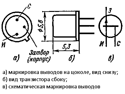 Marking of terminals KP103
 Since the gate is the control output that responds to changes in the electric field in this design, it is better to choose a field-effect transistor in a metal case that is connected to the gate.
 Field effect transistor in a metal case
 Thus, the body of the transistor will serve as a receiving antenna for the electrical wiring signal. Assembling this finder is reminiscent of compiling the simplest electrical circuit at school, so it should not cause difficulties even for a novice master.
 Visual experience with a field effect transistor
 To visualize the process of detecting electrical wiring, in parallel with the source-drain circuit, you can connect a milliammeter or a pointer indicator from an old tape recorder with a ballast resistor, rated 1-10 kOhm (choose empirically).
 Tape recorder indicator
 When the transistor closes (approaching the wiring), the indicator readings will increase, indicating the presence of an electric field and voltage in the hidden wiring. Due to the simplicity of the design, the installation is hinged, on single-core wires with the necessary elasticity.
Search for electromagnetic radiation wiring
Another option for a homemade hidden wiring detector is the use of a milliammeter connected to a high-resistance inductor.
 Homemade wiring finders
 The coil can be homemade, made in the form of an arc, or you can use the primary winding from the transformer by removing part of the magnetic circuit.
 Transformer as receiving antenna
 This detector does not require power - due to the inductance, the receiving coil will act as a current transformer winding, in which an alternating current will be induced, to which the milliammeter will respond.
Many masters use the head from an old tape recorder or player as a receiving antenna. In this case, if the amplifying path has been preserved in working condition, then it is used as a whole, removing the head, connecting it with a shielded cable for ease of search.
 Audio player with a head on the end of the cable
 As in the first case, a buzz of 50 Hz will be heard in the speaker, and its intensity will depend not only on the distance, but also on the strength of the current flowing in the wires.
Advanced Homemade Wire Detectors
Greater sensitivity, selectivity and detection range are provided by hidden wiring detectors made with several amplifying stages based on bipolar transistors or operational amplifiers with elements of logic circuits.
 The scheme and appearance of the seeker on an operational amplifier
 For self-manufacturing of the device according to these schemes, at least minimal experience in the radio business with an understanding of the principles of interaction between the radio components used is required. Without going into the principles of work, two significantly different areas can be distinguished:
- amplification of the signal with its subsequent display in the form of a deviation of the arrow of the indicator or an increase in the intensity of the sound. Here, circuits based on a field-effect transistor or a receiving antenna in the form of an inductor coil are improved with the addition of amplifying stages;
 A simple wiring detector circuit with a bipolar transistor amplifier
 - using the intensity of the electromagnetic field emitted by electrical wiring to change the frequency of visual signals and the tone of the sound alert. Here, the receiving element (field effect transistor or antenna) is included in the frequency control circuit of the pulse generator (single vibrator, multivibrator) based on bipolar transistors, logic or operational microcircuit.
These detectors, although the simplest to manufacture, have significant drawbacks. This is a small detection range, as well as the need for voltage in hidden wiring.
Search for electrical wiring metal
To detect wiring in reinforced concrete structures or under a considerable thickness, without the possibility of applying voltage to the wires, it is necessary to use more complex and accurate designs of detectors that work like metal detectors.
 Working with a professional device
 Self-production of such devices is economically unjustified, and also requires sufficiently deep knowledge in radio engineering, the presence of an element base and measuring equipment. But an experienced master, to test his strength and his own pleasure, can use the metal detector circuits available on the network, and make such devices with his own hands.
 Scheme of a metal detector with a description of its work
 For less experienced craftsmen, if it is necessary to detect hidden wiring without voltage, it will be easier and more profitable to purchase one of such tools as BOSCH, SKIL Woodpecker, Mastech and others.
 BOSCH Universal Wiring Detector
  Universal detector Mastech
 Wiring Finder on Android
Owners of tablet computers and some Android-based smartphones have the opportunity to use their devices as hidden wiring detectors.
 Smartphone as a wire detector
 To do this, you need to download the appropriate software from Google Play. The principle of operation is that these mobile devices have a module that performs the functions of a compass for navigation.
When using the corresponding programs, this module is used as a metal detector.
 Metal Sniffer program that adds a metal detector function to Android devices
 The sensitivity of this metal detector is not enough to search for treasures underground, but it should be enough to detect metal wires at a distance of several centimeters under a layer of plaster.
But it should be remembered that without the use of specialized devices, or the use of a professional metal detector capable of distinguishing metals, it will be impossible to detect electrical wiring hidden in reinforced concrete panels using an improvised Android-based detector.
Good afternoon, dear electronics lovers!
I decided to add and fix something in my apartment network. The time has come for chiselling and drilling walls, but during this procedure I always worry about the question, but will we meet with wiring in the wall, especially near the electric meter?
So, a hidden wiring detector is required!
The detector circuit that "didn't take off"
On the Internet, the following scheme was chosen:I decided to add a little creativity and insert the device into an empty bottle of roll-on antiperspirant.

Due to the simplicity of the circuit, I decided not to make a printed circuit board, but mounted everything on the back and belly of the microcircuit. To power the circuit, I decided to use a Li-Ion battery from an old netbook battery and.

The process of assembling and compacting all the contents into the body has begun.


I decided to make the antenna not from copper wire (as recommended), but from a piece of television coaxial cable. I liked the fact that it is hard, but elastic.
Unfortunately, the work of this scheme did not suit me at all. Experimented with antennas of different lengths, from different materials. Didn't get any result. There was no wiring in the walls.
Modified hidden wiring detector circuit

Then I decided to try to add a field effect transistor to the input of the device, like the factory device "Dyatel E-121". After that, I was very pleased with the result. The device turned out to be sensitive, and quite accurate for a homemade product. Plus, it's powered by a battery that charges with any micro-USB smartphone charger.
The device sees approximately 30 - 50 mm in the wall. Much depends on the intensity of the current in the conductor, on the material of the walls, etc. In addition, electricians say that any such device must be adjusted.
I am writing an article, because such a device is a very convenient, useful and easy-to-assemble design that will be useful to any home craftsman.
A few words about details
The scheme is simple.C1 = 0.1 uF (100 nF), ceramic or film. C2 = 150 pF, ceramic. C3 = 4700 pF (4.7 nF), ceramic or film.
C4 = 50...1000uF x 16V.
All resistors from 0.125 W and above.
Chip K561LA7(4 logical elements "2I-NOT") can be replaced by imported 4011.
There is a special high-resistance resistor R1 in the circuit. I put 100 MΩ. There was no such denomination on the radio market, so I had to make a small "button accordion" of resistors. I do not recommend setting the nominal value less - the sensitivity will decrease.
As a sound emitter, any piezoceramic emitter such as ZP-3, ZP-1, etc. can be used.
For transistor KP103 the most likely replacement for KP303 when switching on (it is with an n-type channel).
KP103 (p-channel) = 2N3329, J174, J175, J176, J177, MMBF5460.
KP303 (n-channel) = 2N3823, J210, J211, J212, MMBF4392.
How they will work in this scheme - you need to experiment, check.
When performing construction work, it often becomes necessary to check the wall for the presence of wiring in it. To conduct a search, you will need a detector that reacts to the metal. You can purchase this device in the factory version or make a do-it-yourself hidden wiring finder. This article will discuss the nuances of the internal structure of the detectors, as well as methods for their manufacture.
Schemes of factory detectors
There are several types of factory-made detectors:
- Electrostatic. The advantages of such a device are the simplicity of the internal structure and the ability to find metal objects at a considerable distance. The disadvantage of the detector is that it can search only in a dry environment. Otherwise, there will be false positives. In addition, only those wires that are energized can be detected.
- Electromagnetic. The advantages are simple circuit and high-precision wire detection. The only drawback, but significant: in addition to voltage, you need a fairly powerful load - at least 1 kilowatt.
- Metal detector. Such a device is a standard metal detector. The main plus is that there is no need for tension. Disadvantages: detects any metal (not just wiring), and is also structurally complex.
The simplest schemes of homemade devices
There are several schemes of such devices.
With sound indication
You can make a simple do-it-yourself hidden wiring detector based on resistor R1. This resistor protects the circuit from induced voltage. Moreover, even if you install it, it most likely will not affect the operation of the device.
 Hidden wiring detector circuit with sound indication
 A copper conductor with a length of 5 to 15 centimeters is used as an antenna. When wiring is detected, a specific crackle is emitted. The piezoelectric element is connected according to the principle of a bridge circuit, which allows you to control the volume level.
Sound indication in combination with light
This circuit is also simple - you only need one chip.
 Hidden wiring finder circuit on a microcircuit
 Features of the circuit: the value of the resistor R1 must be equal to or greater than 50 MΩ. The LED is used without resistance limitation, since the microcircuit performs this task on its own.
On a field effect transistor (first circuit)
The transistors of this group are extremely responsive to the electric field. This feature is used in the diagram below.
 Field-effect transistor wiring finder circuit
 From the figure, you can understand that the device is very simple, you can make it yourself, without using any special tools. The supply voltage indicator is from 3 to 5 V. The current is so small that the detector is able to function for 5-6 hours without shutting down. The antenna coil is fixed with a 0.3-0.5 mm wire on the core, which, in turn, has a diameter of 3 mm. The number of turns depends on the wire itself: 20 turns for a wire of 0.3 mm and 50 turns for a wire of 0.5 mm. The antenna can function both with a frame and without it.
On a field effect transistor (second circuit)
Another option for making a do-it-yourself hidden wiring detector on a field-effect transistor is to use the KP103 chip. This field worker is characterized by high sensitivity. If its gate is in close proximity to the wiring, the resistance is reduced, which leads to the opening of other transistors. After that, the LED starts to glow.
Note! Polevik KP103 can be used with any letter, as well as the light diode AL307. The fact is that bipolar transistors with such conductivity have low power, and the transfer coefficient must be significant. Therefore, instead of KT203, it is recommended to choose KT361.
The device is small in size - the assembly can be carried out even in the housing from the marker. The antenna is pulled through the hole in the marker. The length of the antenna is from 5 to 10 centimeters. However, if the wiring is not too deep in the wall (no deeper than 10 centimeters), you can get by with the leg length of the field-effect transistor.
 Hidden wiring detector circuit on transistor KP103
 The KP103 transistor is installed horizontally, and the gate must be bent so that it is located directly above the transistor housing.
metal detector
 Schematic diagram of a metal detector
 The metal detector circuit looks like this:
- frequency generator (100 kHz) - VT1;
- detector - VT2;
- indication - VT3, VT4.
Generator coils are wound on a ferrite core. Rod diameter - 8 millimeters. The number of turns on the first coil is 120, on the second coil - 45. The wire is selected PEVTL 0.35.
Adjustment of the metal detector must be carried out away from metal products. The tuning is performed by trimmers R3 and R5 in such a way that the generation practically disappears (uneven glow of the diode and low brightness). Next, R3 is tuned in order to fade the emitter.
The next step is to adjust the sensitivity. This is done with a piece of metal (you can use a coin) and a pair of resistors. Moreover, it is recommended to repeat the sensitivity setting periodically. To optimize the process, make it more convenient, regulators can be built into the body of the metal detector.
The tuned device turns on when the antenna is near the metal - the light diode starts flashing.
Wiring indicator without batteries
This detector uses the mains directly as a power source. Such a scheme is possible through the use of a high-capacity capacitor (indicated in the diagram as C1). The capacitor is charged from the network. In a charged state, the capacitor transmits a voltage of 6-10 V. At the same time, only the brightness of the light diode depends on the voltage, but this indicator does not affect the sensitivity of the device.
 Schematic diagram of a hidden wire finder without batteries
 Wiring detector on the microcontroller
 The diagram above shows a hidden wire detector built on the PIC12F629 microcontroller. The operation of the device is based on responsiveness to a magnetic field. This field is formed by current flowing through a conductor located in the wall.
In the circuit, you can use an LED lamp or a piezo emitter. When a magnetic field is detected, a lamp lights up or a piezo emitter starts to crackle, depending on the type of indication preferred.
The advantage of the device is its ability to respond only to a frequency of 50 Hz, which is the frequency of alternating current. Thus, false searcher responses are excluded, since the device will not respond to other frequencies.
Dual element indicator
 Schematic diagram of a two-element detector
 In this case, you need a microcircuit and a light diode. As a microcircuit, you can choose DD1, and it is recommended to take the LED HL1. The task is to connect the leads in such a way as to create three inverters in a circuit. As a result, the device will amplify the currents that flow to the device from the AC field in the wiring located in the wall. When wires are detected, the diode lamp starts to glow. When moving away from the wall or breaking the chain, the lamp goes out.
There are two versions of the scheme:
- Connection of conclusions: the third with the eighth, the second with the tenth, the fourth with the seventh and ninth, the first with the fifth, the eleventh with the fourteenth.
- Connection of conclusions: the third with the eighth, the tenth with the thirteenth, the first with the fifth and twelfth, the second with the eleventh and fourteenth, the fourth with the seventh and ninth.
Industrial circuits of professional detectors
You can assemble at home and a professional-level device. However, such equipment has a rather complex scheme, and it will take a lot of effort to manufacture it. Below are two schemes to choose from: the first refers to an industrial device, the second - to a home-made device "Woodpecker".
 Scheme of an industrial hidden wiring signaling device
  Scheme of a home-made wiring determinant "Woodpecker"
 It is also possible to manufacture a YADITE 8848 type device. Two variants of such a device are shown below.
 Schematic diagram of the detector on the TC4069UBP
  Wiring Finder Schematic on 74HC14AP
 Checking homemade wiring finders
Before using a homemade device, it is recommended to test its performance. Checking will show the correct assembly.
The test is performed as follows:
- We find a site in which there is definitely a hidden wiring. For example, it is guaranteed that we can talk about the presence of wires in the wall going to switches and sockets.
- We check the selected area. To do this, we bring the device to the wall and observe the indication.
- If the signal is received only at the cable passage, the device is working properly and can be used.
- If the signal appears, then disappears in different directions, then the device is faulty.
Advice! Before starting the test, the wiring must receive the maximum load. To ensure such a load, we connect as many electrical appliances as possible to the network. As a result, the magnetic and electric fields are amplified, to which the devices respond.
So, it is not necessary to purchase a wiring detector in a store. This device can be made at home if you follow the above schemes.


