Knowing that a CNC milling machine is considered sophisticated technical and electronic equipment, many craftsmen think that it simply cannot be done by hand.
However, this opinion is not true: you can make such a device with your own hands, but for this you need to have not only its complete drawing, but also a set of certain tools and suitable components.
DIY CNC machine (drawings)
When deciding to create a homemade special CNC machine, remember that this can take a lot of time. In addition, you will need a lot of money.
To make a milling machine that is equipped with a CNC system, you can use 2 methods: purchase a ready-made set of specially selected parts from which such equipment is assembled, or find all the components and independently assemble a device that fully meets all your requirements.
Preparation for work
If you planned to make a CNC machine yourself without using a ready-made kit, then the first thing you will need to do is stop at special scheme, on which such a mini-device will work.

Equipment assembly
The basis of the assembled milling equipment can be a rectangular beam, which must be firmly fixed on the rails.
 The supporting structure of the equipment must have high rigidity. When installing it, it is better not to use welded joints, but to attach all parts only with screws.
In the milling equipment that you will assemble yourself, a mechanism must be provided that will ensure that the working device moves in a vertical direction. It is best to take a screw gear for it, the rotation of which will be transmitted using a toothed belt.
The main part of the machine
An important part of such a machine is its vertical axis, which for a home-made device can be made from an aluminum plate. Remember to the dimensions of such an axis were precisely matched to the dimensions of the device being created.
The aim of this project is to create a desktop CNC machine. It was possible to buy a ready-made machine, but its price and dimensions did not suit me, and I decided to build a CNC machine with the following requirements:
- the use of simple tools (only a drilling machine, band saw and hand tools are needed)
- low cost (I was looking for low cost, but I still bought items for about $600, you can save a lot by buying items in the appropriate stores)
- small footprint(30"x25")
- Normal working space (10" X, 14" Y, 4" Z)
- high cutting speed (60" per minute)
- a small number of elements (less than 30 unique)
- available elements (all elements can be bought in one hardware and three online stores)
- the possibility of successful processing of plywood
Other people's machines
Here are some photos of other machines that have been assembled according to this article

Photo 1 - Chris and a friend assembled the machine by cutting parts out of 0.5" acrylic using laser cutting. But everyone who has worked with acrylic knows that laser cutting is good, but acrylic does not tolerate drilling, and there are many holes in this project They did a good job, more information can be found on Chris' blog I especially enjoyed making the 3D object with 2D cuts.

Photo 2 - Sam McCaskill made a really nice desktop CNC machine. I was impressed that he did not simplify his work and cut out all the elements by hand. I am impressed with this project.

Photo 3 - Angry Monk's used DMF parts cut with a laser cutter and toothed belt driven motors converted to propeller motors.

Photo 4 - Bret Golab's assembled the machine and set it up to work with Linux CNC (I also tried to do this, but I couldn't because of the difficulty). If you are interested in his settings, you can contact him. He did a great job!
I'm afraid I don't have enough experience and knowledge to explain the basics of CNC, but the CNCZone.com forum has an extensive section on homemade machines, which helped me a lot.

Cutter: Dremel or Dremel Type Tool
Axes options:
X axis
Travel Distance: 14"
Speed: 60"/min
Acceleration: 1"/s2
Resolution: 1/2000"
Pulses per inch: 2001
Y-axis
Travel Distance: 10"
Drive: Toothed belt drive
Speed: 60"/min
Acceleration: 1"/s2
Resolution: 1/2000"
Pulses per inch: 2001
Z-axis (up-down)
Travel Distance: 4"
Drive: Screw
Acceleration: .2"/s2
Speed: 12"/min
Resolution: 1/8000"
Pulses per inch: 8000
Required Tools
I aimed to use popular tools that can be purchased at a regular craft store.

Power tool:
- band saw or jigsaw
- drilling machine (drills 1/4", 5/16", 7/16", 5/8", 7/8", 8mm (about 5/16")), also called Q
- Printer
- Dremel or similar tool (to be installed in the finished machine).
Hand tool:
- rubber hammer (for planting elements in place)
- hexagons (5/64", 1/16")
- screwdriver
- glue stick or spray glue
- Adjustable wrench (or socket wrench with ratchet and 7/16" socket)
Necessary materials
The attached PDF file (CNC-Part-Summary.pdf) provides all costs and information about each item. Only summarized information is provided here.

Sheets---$20
- A piece of 48" x 48" 1/2" MDF (any 1/2" thickness sheet will do. I plan to use UHMW in the next version of the machine, but now it is too expensive)
- A piece of 5"x5" 3/4" MDF (this piece is used as a spacer, so you can use any 3/4" piece of material)
Motors and controllers --- $255
-A whole article can be written about the choice of controllers and motors. In short, you need a controller capable of controlling three motors and motors with about 100 oz/in torque. I bought motors and a ready-made controller and everything worked well.
Hardware --- $275
-I bought these items in three stores. I got the simple parts from the hardware store, the specialized drivers I got from McMaster Carr (http://www.mcmaster.com), and the bearings, which I need a lot, I bought from an online retailer for $40 for 100 pieces (it's quite a bargain). , many bearings remain for other projects).
Software --- (Free)
-You need a program to draw your design (I use CorelDraw) and I'm currently using a trial version of Mach3, but I have plans to switch to LinuxCNC (an open source machine controller using Linux)
Head Unit --- (Optional)
-I installed Dremel on my machine, but if you are interested in 3D printing (like RepRap) you can install your device.
Printing templates
I had some experience with a jigsaw, so I decided to glue on the templates. It is necessary to print PDF files with templates placed on the sheet, stick the sheet on the material and cut out the details.

File name and material:
All: CNC-Cut-Summary.pdf
0.5" MDF (35 8.5"x11" template sheets): CNC-0.5MDF-CutLayout-(Rev3).pdf
0.75" MDF: CNC-0.75MDF-CutLayout-(Rev2).pdf
0.75" aluminum tube: CNC-0.75Alum-CutLayout-(Rev3).pdf
0.5"MDF (1 48"x48" pattern sheet): CNC-(One 48x48 Page) 05-MDF-CutPattern.pdf
Note: I am attaching CorelDraw drawings in original format (CNC-CorelDrawFormat-CutPatterns (Rev2) ZIP) for those who would like to change something.
Note: There are two options for MDF 0.5". MDF-CutPattern.pdf) with one 48"x48" sheet for printing on a large format printer.
Step by step:
1. Download three PDF templates.
2. Open each file in Adobe Reader
3. Open the print window
4. (IMPORTANT) Disable Page Scaling.
5. Check that the file has not been scaled by accident. The first time I did not do this, and printed everything at a scale of 90%, as described below.
Gluing and cutting elements
Glue the printed templates on the MDF and on the aluminum pipe. Next, just cut out the part along the contour.


As mentioned above, I accidentally printed the templates at 90% scale, and did not notice this until I started cutting. Unfortunately, I did not understand this until this stage. I was left with 90% scale templates and moving across the country I got access to a full size CNC. I could not resist and cut out the elements with this machine, but I could not drill them from the back. That is why all the elements in the photos are without template pieces.

drilling
I didn't count exactly how many, but this project uses a lot of holes. The holes that are drilled on the ends are especially important, but take the time to make them, and you will rarely need to use a rubber hammer.
Places with holes in the lining on top of each other is an attempt to make grooves. Perhaps you have a CNC machine that can do this better.
If you have reached this step, then I congratulate you! Looking at a bunch of elements, it's quite hard to imagine how to assemble the machine, so I tried to make detailed instructions similar to instructions for LEGO. (attached PDF CNC-Assembly-Instructions.pdf). The step-by-step photos of the assembly look quite interesting.


Ready!
The machine is ready! I hope you made and run it. I hope that the article does not miss important details and points. Here is a video that shows the machine cutting a pattern on pink foam.

Axle arrangementX, Y, Zdesktop CNC milling and engraving machine:
The Z axis moves the tool (milling cutter) vertically (up and down)
Axis X - moves the carriage Z in the transverse direction (left-right).
Y-axis - moves the movable table (back and forth).
The device of the milling and engraving machine can be found
The composition of the set of CNC machine Modelist2020 and Modelist3030
I A set of milled parts made of 12mm plywood for self-assembly
A set of milled parts for the assembly of a CNC machine with a sliding table consists of:
1) CNC router gantry legs
2) a set of CNC milled parts to assemble the Z axis
3) A set of CNC milled parts to assemble the sliding table
4) a set of milled CNC machine parts for assembling stepper motor supports and spindle mounting
II Set of milling machine mechanics includes:
1. coupling for connecting the stepper motor shaft with the lead screw of the machine - (3 pcs.). The size of the coupling for the Modelist2030 machine with NEMA17 stepper motors is 5x5mm. For Modelist3030 machine with Nema23 stepper motors - 6.35x8mm
2. steel linear guides for CNC machine Modelist3030:
16mm (4pcs) for X and Y axes,
12mm(2pcs) for Z axis
For CNC machine Modelist2020, the diameter of the linear movement guides:
12mm(8pcs) for X, Y and Z axes.
3. linear rolling bearings for milling machine Modelist3030:
Linear bearings LM16UU (8pcs) for X and Y axes,
Linear bearings LM12UU for Z axis.
For CNC milling machine Modelist2020
Linear bearings LM12UU (12pcs) for X, Y and Z axes.
4. lead screws for the milling machine Modelist2020 - M12 (pitch 1.75mm) - (3pcs) with processing under d=5mm from one end and under d=8mm from the other.
For the milling machine Modelist3030 - TR12x3 trapezoidal screws (pitch 3mm) - (3 pcs.) with end processing under d = 8mm.
5. radial bearings for fastening the lead screws - (4pcs) one bearing in an aluminum block for the Z axis.
6. running nuts made of graphite-filled caprolon for the X, Y and Z axes (- 3 pcs.)
III CNC milling machine electronics set:
1. For CNC machine Modelist2020: NEMA17 stepper motors 17HS8401(size 42x48mm, torque 52N.cm , current 1.8A, phase resistance 1.8Ω, inductance 3.2mH, shaft diameter 5mm)- 3 pcs.
For CNC machine Modelist3030: stepper motors 23HS5630 (size 57x56mm, torque 12.6kg*cm, current 3.0A, phase resistance 0.8Ω, inductance 2.4mH, shaft diameter 6.35mm)- 3 pcs.
2. CNC stepper motor controller based on specialized Toshiba TV6560 microstepping drivers in a closed aluminum case
3. power supply 24 V 6.5 A for CNC machine Modelist2020 and 24V 10.5A for CNC machine Modelist3030
4. set of connecting wires
The assembly sequence of the CNC milling machine with a movable table.
The linear movement system of any machine tool consists of two parts: a linear bushing is an element that moves and a fixed element of the system - a linear guide or shaft (linear support). Linear bearings can be of different types: bushing, split bushing, aluminum bushing for easy mounting, ball carriage, roller carriage, the main function of which is to bear the load, ensuring stable and accurate movement. The use of linear bearings (rolling friction) instead of sliding bushings can significantly reduce friction and use the full power of stepper motors for useful cutting work.
Picture 1
1 Lubricate the linear bearings of the system linear movement of the milling machine with special grease (you can use Litol-24 (sold in auto parts stores)).
2 Assembling the Z axis of the CNC milling machine.
The assembly of the Z axis is described in the instruction ""
3 CNC milling table assembly, Y axis
3.1 Details for assembling the portal, figure 2.
1) a set of milled parts
4) lead screws for the milling machine Modelist2030 - M12 (pitch 1.75mm) with end machining for d=8mm and d=5mm

Figure 2. Details of the portal milling desktop CNC machine
3.2 Press in the linear bearings and insert the linear bearing holders into the milled grooves, Figure 2. Insert the linear guides into the linear ball bearings.
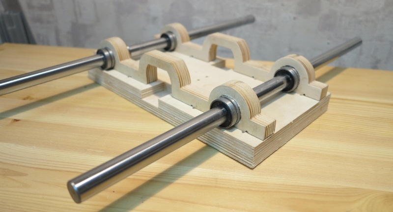
Figure 2 Assembling the table of a desktop CNC milling machine
3.3 The linear bearing holders are driven into the grooves of the sliding table part. The thorn-and-groove connection provides excellent rigidity of the knot, all parts of this knot are made of 18mm plywood. Additionally, by tightening the parts with a bolted connection, we will ensure a long and reliable service life, for this, through the existing hole in the plate, which serves as a guide for the drill, we drill a hole in the end face of the linear bearing holder, as shown in Figure 3, a drill with a diameter of 4mm.

Figure 3 Drilling mounting holes.
3.4 We impose the table itself and, through the existing holes, we fasten it with the help of M4x55 screws from the kit, Figure 4 and 5.

Figure 4 Mounting the slide table bearings.

Figure 5 Mounting the slide table bearings.
3.5 Press the thrust bearings into the details of the table frame. Insert the lead screw with lead nut made of graphite-filled caprolon into the thrust bearings and linear guides into the grooves of the frame elements, Figure 6.

Figure 6. Assembly of the sliding table.
Fasten the frame elements with screws from the kit. For fastening from the sides, use screws 3x25mm, Figure 7. Before screwing in the screws, be sure to drill with a 2mm drill to avoid delamination of the plywood.
If the lead screw is not clamped by the parts of the base of the movable table and there is play of the screw along the axis in the support bearings, use a washer with a diameter of 8 mm, Figure 6.
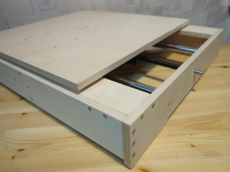
Figure 7. Assembly of the frame of the desktop machine.
3.6 Center the drive nut between the linear bearings and make holes for the screws with a 2mm drill, Figure 8, then use the 3x20 screws from the kit to secure the drive nut. When drilling, be sure to use a stop under the spindle nut so as not to bend the spindle. .
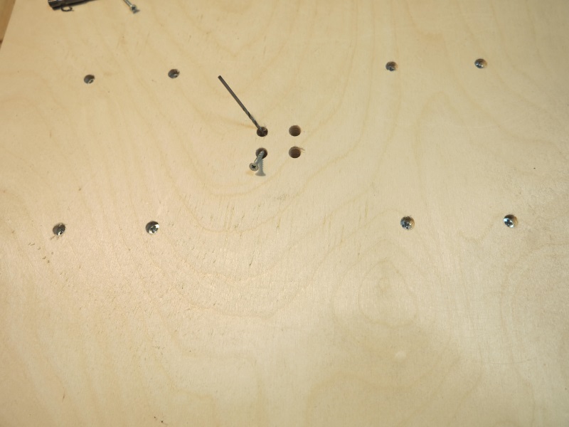
Figure 8. Fastening the running nut.
4 Assembling the portal of the machine.
For assembly you will need:
1) a set of milled parts for assembling the sliding table
2) steel linear guides with a diameter of 16mm (2pcs)
3) linear bearing LM16UU(4pcs)
4) lead screws for the milling machine Modelist2030 - M12 (pitch 1.75mm) with end machining under d=8mm and d=5mm.
For milling machine Modelist3030 - TR12x3 trapezoidal screws (pitch 3mm) with end machining under d=8mm.
5. radial bearings for fastening the lead screws - (2 pcs.)
6. running nut made of graphite-filled caprolon - (- 1 pc.)
4.1 Fasten the sidewall of the portal, Figure 9.

Figure 9. Machine portal assembly.
4.2 Insert the lead screw with nut into the frame of the Z-axis carriage, figure 10.

Figure 10 Lead screw installation.
4.3 Insert linear guides, figure 11.

Figure 19 Fastening the lead screw "in the thrust".
4.4 Fasten the second side of the portal, Figure 11.
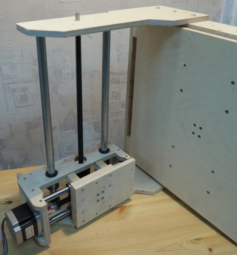
Figure 11. Installing the second side of the portal
If the lead screw is not clamped by the parts of the base of the movable table and there is play along the axis, use a washer with a diameter of 8mm.
4.5 Install and secure the rear wall of the carriage Z, Figure 12.

Figure 12. Fastening the rear wall of the Z carriage.
4.6 Fasten the caprolon running nut with 3x20 screws from the kit, Figure 13.

Figure 13. Attaching the X Axis Lead Nut.
4.7 Fasten the rear wall of the portal, Figure 14, using 3x25 screws from the kit. 
Figure 14. Fastening the rear wall of the portal.
5 Installation of stepper motors.
To install stepper motors, use the fasteners from the set of milled parts of the CNC machine to assemble the Nema23 stepper motor supports for the Modelist3030 milling machine.

Figure 15. Installation of stepper motors.
Install 5x8mm couplings to connect the motor shaft to the lead screw. Fasten the stepper motors to the machine, for fastening use the M4x55 screw from the kit, Figure 15.
6 Attach the controller to the back of the router, and connect the motor terminals to it.
7 Installing the router.
The router is fastened by the neck of the tool or the body. The standard diameter of the neck of household routers is 43mm. Spindle diameter 300W - 52mm, mounted on the body. For installation, assemble the router mount, fastening details in Figure 16. Use the 3x30mm screw from the kit.
Figure 16 Spindle mount 43mm
Figure 17 CNC Mounted Spindle
When installing Dremel similar tools (engravers), in addition, you will need to additionally fasten the engraver body to the Z carriage with a clamp, Figure 18.

Figure 18 Mounting the engraver on the milling machine.
It is possible to install a nozzle for connecting a vacuum cleaner
For the manufacture of a three-dimensional pattern on a wooden surface, factory ones are used. It is difficult to make a similar mini-model with your own hands at home, but it is possible with a detailed study of the design. To do this, you need to understand the specifics, choose the right components and configure them.
The principle of operation of the milling machine
Modern woodworking equipment with a numerical control unit is designed to form a complex pattern on wood. The design must contain a mechanical electronic part. In combination, they will automate the work process as much as possible.
To make a desktop mini wood router with your own hands, you should familiarize yourself with the main components. The cutting element is a cutter, which is installed in a spindle located on the motor shaft. This design is attached to the frame. It can move along two coordinate axes - x; y. To fix the workpiece, it is necessary to make a support table.
The electronic control unit is connected to the stepper motors. They provide displacement of the carriage relative to the part. Using this technology, you can make 3D drawings on a wooden surface.
The sequence of operation of mini-equipment with CNC, which you can make yourself.
- Writing a program according to which the sequence of movements of the cutting part will be performed. To do this, it is best to use special software systems designed for adaptation in home-made models.
- Setting the workpiece on the table.
- Program output to the CNC.
- Turning on equipment, monitoring the implementation of automatic actions.
To achieve maximum automation of work in 3D mode, you will need to correctly draw up a diagram and select the appropriate components. Experts recommend studying factory models before making a mini.
To create complex patterns and patterns on a wooden surface, you will need several types of cutters. Some of them you can do yourself, but for fine work, you should purchase factory ones.
Scheme of a homemade milling machine with numerical control

The most difficult stage is the choice of the optimal manufacturing scheme. It depends on the dimensions of the workpiece and the degree of its processing. For home use, it is desirable to make a do-it-yourself desktop mini CNC milling machine that will have the optimal number of functions.

The best option is to make two carriages that will move along the x coordinate axes; y. It is best to use ground steel bars as a base. Carriages will be mounted on them. To create a transmission, stepper motors and screws with rolling bearings are needed.
For maximum automation of the process in a do-it-yourself wood construction, it is necessary to think over the electronic part in detail. Conventionally, it consists of the following components:
- power unit. It is necessary to supply electricity to stepper motors and the controller chip. Often use the model 12v 3A;
- controller. It is designed to give commands to electric motors. For the operation of a do-it-yourself mini CNC milling machine, a simple circuit is enough to control the functioning of three motors;
- driver. It is also an element of regulation of the operation of the moving part of the structure.
The advantage of this complex is the ability to import executable files of the most common formats. Using a special application, you can create a three-dimensional drawing of the part for preliminary analysis. Stepper motors will run at a certain stroke rate. But for this, technical parameters must be entered into the control program.
Choice of accessories for CNC milling machine

The next step is to select components for assembling homemade equipment. The best option is to use improvised means. As a basis for desktop models of a 3D machine, you can use wood, aluminum or plexiglass.
For the correct operation of the entire complex, it is necessary to develop the design of calipers. During their movement, there should be no vibrations, this can lead to inaccurate milling. Therefore, before assembly, all components are checked for compatibility with each other.
- guides. Polished steel bars with a diameter of 12 mm are used. The length for the x-axis is 200mm, for the y-axis it is 90mm;
- caliper. Textolite is the best option. The usual size of the platform is 25*100*45 mm;
- stepper motors. Experts recommend using models from a 24v, 5A printer. Unlike disk drives, they have more power;
- cutter block. It can also be made from textolite. The configuration directly depends on the available tool.
The power supply is best assembled from the factory. In self-manufacturing, errors are possible, which subsequently affect the operation of all equipment.
The procedure for manufacturing a CNC milling machine

After selecting all the components, you can make a desktop mini milling machine yourself with your own hands. All elements are preliminarily checked again, their dimensions and quality are checked.
To fix the elements of the equipment, it is necessary to use special fasteners. Their configuration and shape depend on the chosen scheme.
The procedure for assembling desktop mini CNC equipment for wood with a 3D processing function.
- Installation of caliper guides, their fixation on the side parts of the structure. These blocks are not installed on the base yet.
- Lapping of calipers. They must be moved along the guides until a smooth ride is obtained.
- Tightening the bolts to fix the calipers.
- Attaching components to the base of the equipment.
- Installation of lead screws together with couplings.
- Installation of drive motors. They are attached to the coupling screws.
The electronic part is located in a separate block. This helps to reduce the likelihood of malfunction during the operation of the router. Also an important point is the choice of a working surface for the installation of equipment. It must be level, since the level adjustment bolts are not provided in the design.
After that, you can start trial tests. It is recommended to set up a simple wood milling program first. During operation, it is necessary to check each cutter pass - the depth and width of processing, especially in the 3D mode.
The video shows an example of how to assemble a large do-it-yourself CNC milling machine:
Examples of drawings and homemade designs
This article discusses home-made machines and fixtures for the home workshop. It details the features of the most popular and necessary DIY tools, as well as fixtures for a workshop or garage, step-by-step technologies for their manufacture, and other useful recommendations on this topic.
Many owners of home workshops create the equipment they need with their own hands.
Homemade machines and fixtures for the home workshop: general information
Each owner of a garage or workshop, depending on his needs, selects the equipment himself. Many of them know how home-made machines and fixtures for garages are made, so they manage on their own when arranging the premises, adjusting the technical features of the structures for themselves.
So, when creating metal drawings and the dimensions of the product on them, they can be adjusted to the parameters of the room and other conditions. Even a small home workshop will need to allocate enough space to accommodate at least the construction of a universal folding workbench and a minimal set of tools. The required area for this is at least 3-5 m².

Helpful advice! It is better to equip the workshop in a separate room so that the noise from the work of a home-made wood grinder and other tools does not interfere with the residents. Under the placement of machines, you can take a garage, the area of \u200b\u200bwhich is enough for comfortable work and installation of equipment.
Manufacture of tool storage devices: shelves, racks
In fact, it is very difficult to achieve optimal working conditions. It is desirable that the size of the room be at least 6.5 m. To equip the workshop, you can make an extension to the house or garage. This decision will be the most profitable in any case.
Before you design a drawing of a folding workbench with your own hands, which has the most overall design (therefore, its dimensions are taken into account in the first place), it is worth deciding on some points:
- indicate what types of work will be performed in the workshop;
- determine the list of necessary tools and equipment.
By mounting the tool on the wall, you can significantly save useful space in the workshop. Shelves or racks are perfect for this. You can successfully arrange these structures, achieving the most rational distribution of the area.

In order to save space, you can get a special device for a circular saw with your own hands, made on the basis of a conventional drill. Such a universal machine can perform several functions at once, combining the possibilities:
- circular saw;
- grinding machine;
- grindstone;
- cutting machine.
The work table can be combined with a carpentry workbench and equipped with drawers to store small tools.
DIY tool shelves: popular designs
Metal structures are more durable and reliable, while wooden structures are affordable.
There are several options for rational storage of tools:
- wall shelves;
- do-it-yourself tool racks;
- suspended ceiling shelves;
- Shelves-shields for hanging small tools.

Helpful advice! The shield shelf is very convenient for metalwork and carpentry work. You can install tool holders or hooks, small shelves or containers for fasteners on it. It is best to hang such a structure over a folding carpentry workbench. You can even bring additional lighting. It is better to use a small lamp for this.
Do-it-yourself tool shelf manufacturing technology (shield):
- A shield is cut out of a plywood sheet, the places where the shelves will be installed are marked on it.
- Using a jigsaw, shelves with side walls are cut out. The length of these sides should match the length of the shield.
- Shelves for tools are assembled and fixed on the surface of the shield using long self-tapping screws.
- Hooks are being installed. Holes are made in the shield where dowels are installed. They need to be screwed into special hooks equipped with threads. First, it is worth distributing the entire tool and designating the points where it will hang.
- Brackets or lugs are mounted on the rear wall of the structure.
It remains only to fix the shelf-shield on the wall. To prevent the eyes from slipping off the anchors, it is recommended to fix them with special washers.

Making a carpentry workbench with your own hands: drawings, videos, technology
The following details must be present on the drawing of the carpentry workbench:
- Work surface - for its manufacture it is recommended to take a board with a thickness of 6 cm or more. Suitable wood species such as oak, hornbeam or beech. It is allowed to use several narrow boards pre-treated with drying oil.
- On the top cover, a do-it-yourself design of a do-it-yourself vice is attached, which should also be included in the drawing. If it is planned to install a large-sized product, it is better to take wood for its manufacture. It is allowed to manufacture and subsequent installation of small do-it-yourself metalwork vise made of steel.
- Workbench supports - can be made from linden or pine. Between them, it is imperative to establish a longitudinal connection in the form of strips. This will increase the stability of the table.
- Shelves for storing tools - mounted under the workbench. Structures can be fixed or retractable.
Helpful advice! The linear parameter of the workbench can exceed 1 m. The increased size of the structure can be used to install two carpentry vices with your own hands.
There are several modifications of workbenches:
- mobile;
- stationary;
- folding (universal).
Having familiarized yourself with the device of the carpentry workbench, you can begin to manufacture it.
Do-it-yourself technology and drawings of a carpentry workbench: how to make a simple design
Step-by-step construction technology:
- To make the cover of a wooden carpentry workbench, you will need to take thick boards. The size must be chosen so that as a result of their connection a shield with parameters of 0.7x2 m is obtained (the length can be less than 2 m). Long nails should be used as fasteners, which must be hammered from the front side and bent from the inside.
- You can finish the cover by fixing a bar with a section of 50x50 mm along its lower perimeter.
- Depending on the size of the carpentry workbench (its cover), vertical supports are located. For their manufacture, a bar is taken (12x12x130 cm). At this stage, it is necessary to take into account the height of the working surface, because it should be comfortable. The upper limit of the support should be at the level of the lowered hands. Subsequently, due to the installation of the cover, about 8-10 cm will be added to this indicator. The markings for the installation of the bars should be applied to the ground and these elements should be dug to a depth of 0.2-0.35 m.
- Next, do-it-yourself installation of the frame part and the cover of the workbench made of wood is carried out. Installed support bars must be connected in pairs. For this, wide boards are used, fixed at a height of 0.2-0.4 m with long self-tapping screws. At the ends of the supports, a cover is fixed using the same fasteners.
Note! Do not use nails to mount the cover. In the process of driving them, the frame part of the product may move.

Manufacturing technology of a universal wooden workbench with your own hands
Despite the fact that the technology for creating this design is in many ways similar to the previous version, for the manufacture of a composite carpentry workbench, drawings with dimensions will be required without fail. But in this case, bolts are used instead of self-tapping screws.
In addition, in a folding universal workbench with your own hands, you can install drawers for storing tools.
Do-it-yourself folding workbench manufacturing technology:
- Vertical supports are installed in a similar way and are interconnected using horizontal jumpers. Before mounting jumpers, they should be grooved for nuts and washers. To do this, it is better to use a hammer and a chisel.
- When the jumpers are set at the required level, through holes are made in a horizontal bar and a vertically mounted support. A long bolt will be inserted here. On the side where there is a groove for fasteners, a nut and washer are put on, after which the element is well pulled together.
- Horizontal jumpers for the frame part of a home-made carpentry workbench will need 2 pcs. on each of the 4 sides. You will also need a couple of jumpers for installation under the work surface (in the center). The elements under the worktop are designed for drawers. The distance between these jumpers must correspond to the dimensions of the boxes.
- Bolts are also used to fix the work surface. Mounting recesses are prepared at the ends of the supports, and holes for fasteners are prepared on the countertop. The bolts are installed so that their heads are recessed (by 1-2 mm).

Note! Folding workbench drawings are not as complicated as they might seem. The advantage of the design is that any damaged part can be easily replaced with a new one.
Do-it-yourself carpentry vise design for a workbench
Usually workbenches are equipped with a vise. Many owners of garage workshops know how to make such a device with their own hands. For a homemade design, you will need special studs. Such fasteners are sold in hardware stores.
To work, you will need a special screw pin. This threaded part is the main active component of the structure. The minimum pin diameter is 2 cm, the cutting length is 15 cm. The longer this part is, the wider the vise can be spread. If these dimensional parameters are taken into account in the drawings of the vise with your own hands, you can get a design that is bred by almost 8 cm.
The jaws of the tool are made from a pair of boards. One part of the part will be fixed. To make it, you need to take pine. The second part measuring 2x1.8x50 cm will move. In each of these boards you need to make a hole for the screw. Using a drill with a diameter of 1 cm, holes for studs are formed in all boards at the same time. To prevent the holes from moving relative to each other, you can connect them with nails.
After all the holes are made, the screw and all the studs are inserted into them along with the washer and nut.
Helpful advice! To be able to process workpieces of different sizes, you need to make the studs rearrangeable. You will need to make a couple of additional holes in each of the boards, located near the screw clamp.
Additionally, you can use the video material below to create a vise with your own hands.
Making a locksmith workbench with your own hands: how to make a metal structure
For locksmith work, it is better to make a metal workbench with your own hands, because a wooden workbench is not suitable for this. The thing is, wood is not that strong. In addition, when working with metal blanks, a countertop made of this material will be constantly damaged and will quickly become unusable.
In the general drawing of a do-it-yourself locksmith workbench, five main structural components can be distinguished:
- For longitudinal rigidity of the product, horizontal beams (3 pcs.) 6x4 cm in size are used. Length - slightly more than 2 m.
- Rack-mounted small-sized beams (9 pcs.) Made of profiled pipes 6x4 cm in size. They are used to assemble the frame part of the pedestals. In the corner area there are weld-on spacers made of steel strips. Due to all these elements, the frame is rigid and very durable.
- Rack beams (4 pcs.) 9-10 cm long (section 6x4 cm). To do this, it is better to use metal profile pipes with thick walls (more than 2 mm).
- Corner No. 50 (4 pcs.), Which will be used as vertical racks. The height of these elements is 1.7-2 m. Working tools will be attached here.
Locksmith workbench dimensions:
Helpful advice! In order to make high-quality seams, it is recommended to use a carbon dioxide semiautomatic device. Experienced craftsmen can use a pulse type welding machine. In the absence of skills in handling this tool, it is better to entrust the work to professionals.
Do-it-yourself workbench manufacturing technology: how to assemble
Making a universal workbench with your own hands begins with assembling the frame. To do this, take a couple of short and a couple of long beams. During the welding process, these elements may be subjected to twisting.
To prevent this, you must:
- Lay out the parts on a perfectly flat plane.
- At the locations of the docking nodes (there are 4 of them), the beams are tacked using the spot welding method.
- After that, all welding seams are fully completed. First on one side of the frame, then on its reverse side.

Then the rear vertically arranged racks and the rear beam (long, one of three) are attached. Be sure to check how evenly in relation to each other they are placed. If there are any deviations, the beams can be carefully bent with a hammer. At the end, the rest of the rack elements are assembled with a vertical arrangement, as well as elements that provide rigidity.
When the frame is ready, corners can be welded to it, designed to strengthen the structure. The tabletop is formed from wooden boards. They must first be impregnated with a fire-resistant liquid. Then a sheet of metal is laid on top.
A plywood shield for tools can be attached to the vertical rack elements. The same material is used to sew up cabinets. For boxes, you can use metal boxes or make wooden structures.
You can use it in order to understand in more detail the technology of making a workbench with your own hands, the video, which is located below:
Features of creating a wood lathe for a home workshop
In the technology of manufacturing a lathe for wood with your own hands, the frame occupies a special place. The operation of other parts, as well as the stability of the entire structure, directly depends on this part. It can be metal or wood.
Helpful advice! For the manufacture according to standard drawings of a wood lathe with your own hands, it is better to use an electric motor that can reach a speed of 1500 rpm. The optimal power indicator is 200-250 watts. If you plan to process large workpieces, you can increase the power ratings.
To create a wood lathe with your own hands, you can use the old one, which is no longer needed. This tool is placed on a plywood platform 1.2 cm thick and 20x50 cm in size. First, you need to make holes in it for fasteners. Stops from the bars will also be mounted here. They are necessary in order for the cutter to be in a fixed state. The router itself is fastened with two nails between the clamps.
In fact, it is quite easy to make a copying design of a home-made wood lathe with your own hands - there are enough video materials on the net.

An example of a do-it-yourself homemade wood lathe
For the base, it is better to take a steel profile with thick walls. To make the design reliable, it is recommended to use two supports. A bed will be installed on top of them. To fasten parts, a groove type of connection is used. First you need to make support platforms designed for headstocks (rear and front).
The list of parts for a wood lathe (how to assemble the structure yourself based on this list is easy to understand):
- Power component - you can use an electric motor from an old pump or washing machine.
- Headstock (rear) - a head from a drill with a high power reserve is suitable.
- Headstock (front) - to organize this part, it is better to buy a factory spindle equipped with 3-4 pins. This makes it possible to shift the workpiece with respect to the rotational axis.
- The supporting element - the table for cutters can be of absolutely any configuration, the main thing is that it provides comfort during work.
- Pulley - is a connecting element between the headstock and the shafts in the electric motor.
Note! To work with this design, you will need to purchase a set of factory cutters. If you have the right tool, you can make them yourself, but you will need tool steel.
As auxiliary information, you can use a video that reflects this process in detail to assemble a wood lathe with your own hands.
The second example of a do-it-yourself woodworking lathe
An alternative solution would be to make the design of the simplest mini-lathe for wood with your own hands based on an electric drill. This example of technology can be used as a test before building a more serious tool.
This type of machine is suitable for processing small wood blanks. The material for the bed can serve as bars of wood. The tailstock can be replaced with a combination of a shaft mounted on a thrust bearing. To fix the workpiece, you will need to get the appropriate one.
This design has its drawbacks, they are associated with:
- high probability that there will be errors in milling;
- low level of reliability;
- the inability to process large-sized wooden blanks.

But you should not refuse this option, because it is the basis of technologies for creating more advanced and complex turning tools. To correctly calculate the design, determine for yourself the necessary operational properties and technical characteristics.
The principle of making cutters for a wood lathe
The technology in this case is complicated only by the correct choice of workpieces, which must not only have a level of hardness of the cutting edge that meets the requirements, but also be correctly installed in the retainer - holder.
Note! In the absence of tool steel, you can get by with improvised means. After the preliminary preparation stage is completed, the material is further hardened.
- The bars have become reinforcing - it is better to use options that have factory initial dimensions and a square cross-sectional shape.
- Files or rasps - worn workpieces will do, but material with deep chips or cracks is not allowed to be used.
- Automobile springs - before using these blanks, they will need to be squared, which not everyone can do. For this purpose, a welding machine is useful. An autogen will do.
 Turning: A - with a semicircular blade for rough turning; B - with a straight blade for fine turning; B - shaped; G - machine through passage
On the machine, it is possible to provide for the possibility of changing cutters. To do this, a special modification of the housing is made with the necessary mounting parts. These elements must be strong enough to withstand the loads during operation and at the same time maintain the original location of the edge part.
When the cutter is made, it is sharpened, and the cutting edge is hardened. After the cutting part has become hot, the cutter must be dipped in engine oil. With the help of slow hardening technology, the surface of the product can be made as hard as possible. In this case, the heated billet should cool down in a natural mode.
Do-it-yourself knife sharpeners: drawings and recommendations
To make a sharpener from an engine from a washing machine with your own hands, you can limit yourself to a motor from an old Soviet design, for example, CMP-1.5 or Riga-17. A power of 200 watts will be enough, although you can increase this figure to 400 watts by choosing a different engine option.
The list of parts needed for a do-it-yourself grinding machine includes:
- tube (to carve a flange);
- nut for fixing the stone on the pulley;
- metal for the manufacture of a protective cover for a sharpener with your own hands (thickness 2, -2.5 mm);
- grinding stone;
- electrical cable cord having a plug;
- starting device;
- a corner made of metal or a bar of wood (for the bed).
The flange diameter must match the hub dimensions on the motor. In addition, a grindstone will be put on this part. On the one hand, this element is carved. The indent should be equal to the thickness of the circle multiplied by 2. The thread is applied with a tap. On the other hand, the flange must be pressed onto the motor shaft by heating. Fixation is carried out by bolting or welding.
Helpful advice! The thread should go in the opposite direction relative to the direction in which the rotational movements of the motor are performed. Otherwise, the nut that fixes the circle will unwind.
The working winding of the motor is connected to the cable. It has a resistance of 12 ohms, which can be calculated using a multimeter. The starting winding for a do-it-yourself knife sharpener will have 30 ohms. Then the bed is made. It is recommended to take a metal corner for her.
Some people need . You can make such a design with your own hands from a bed with 3 supports, two spindles, a stepper motor (2 kW) and pipes used as holders.
Instructions for creating a stationary circular saw with your own hands
Creating a table for a hand-held circular saw with your own hands is the most important step in creating a machine, since this design will accommodate the main parts of the equipment in the form of:
- power unit;
- control block;
- cutting component;
- other components.
The base frame on the table for hand tools acts as a do-it-yourself guide for a circular saw. It controls the direction in which the cut is made and fixes the workpiece.

A sawmill is a modification of a circular saw. The only difference is that the disc is placed at the bottom. The do-it-yourself function of the bed is assigned to the design of the table for a circular saw. A power unit, a block, a fixing disk and a control system are also installed here.
At the design stage for a circular saw with your own hands drawings, some factors should be taken into account:
- The depth to which the material will be cut - the indicator depends on the geometry of the disk.
- The power level of the electric motor - a specific indicator of 800 watts will be enough.
- Mounting area of the control system - the control should be located as far as possible from the disk.
- Rotational speed - the minimum allowable rate is 1600 rpm, otherwise the color will change during the cutting process.
Helpful advice! If the table is made for the manual version of the tool, it is recommended to make the tabletop metal. A sheet of metal should be equipped at the base with stiffeners.

How to make a circular saw from a grinder with your own hands
First, a tabletop is made of sheet material. Marking is applied to it in accordance with the size of the toolkit. According to this markup, cutouts are made for installing the saw.
- Installing a parallel stop for a circular saw with your own hands, made of a wooden slat. The element is fixed on the tabletop.
- Groove for emphasis - these elements are formed on the tabletop by milling.
- Installation of a ruler for measurements - the installation area is located at the front edge of the cutting element. The ruler will be used to control the dimensional parameters of the blanks.
- Installation of clamps is an additional component for fixing the workpiece.
For a do-it-yourself circular saw machine, you will need legs. They are mounted taking into account the dimensions of the tabletop made of wooden beams with a section of 4x4 cm. Use is allowed. To provide additional stability, stiffeners should be installed between the supports. A control unit is placed next to the workplace. Do not refuse to install RCDs and devices that protect the engine from overloads.

The technology of creating a cutting machine for wood
Manufacturing technology of a homemade cutting machine:
- Cutting parts from the corner for frame assembly (total size - 120x40x60 cm).
- Frame assembly by welding.
- Fixing the channel (guide) by welding.
- Installation of vertical racks (2 pcs.) on the channel (bolted connection).
- Assembling a frame from pipes for installing an electric engine and a shaft at the required slope (45x60 cm).
- Installation of a plate with an engine at the rear of the frame.
- Manufacture of a shaft complete with flanges, supports and a pulley (flange protrusion height - 3.2 cm).
- Installation of supports, bearings and pulleys on the shaft. Bearings are fixed on the upper frame in recesses made in the plate.
- Installation of a box with an electrical circuit on the lower section of the frame.
- Installation of the shaft in the area between the racks. Diameter - 1.2 cm. A sleeve with the minimum possible clearance must be put on over the shaft, so that these elements slide.
- Welding a rocker arm made of a channel (80 cm) onto a bushing. The size of the arms of the rocker should be within the following ratio: 1:3. From the outside it is necessary to fix the springs.

Helpful advice! Experts advise using an asynchronous motor. Such a motor is not particularly demanding. For networks with 3 phases, a motor with a power of 1.5-3 kW is required, for single-phase networks this figure must be increased by a third. You will need to connect with a capacitor.
It remains to mount the motor on the short arm of the rocker arm. A cutting element is placed on the long arm. The shaft and motor are connected by a belt drive. For the countertop, you can use a sheet of metal, a planed board.
Assembling a drilling machine with your own hands: video how to make a design, recommendations
A good drawing of a drilling machine from a drill with your own hands is the main condition for acquiring the necessary tools. To create such a machine, you do not need to use special materials and buy additional components.
Components for the design of a homemade drilling machine with your own hands:
- bed (base);
- rotary mechanism (drill);
- supply device;
- vertically located stand for fixing the drill.

In mastering the technology of manufacturing a drilling machine from a drill with your own hands, video material can be of invaluable assistance.
A guide to creating a drilling machine with your own hands (how to make the simplest design):
- For a rack, it is better to use DPS so that the part turns out to be massive or a furniture plate with a thickness of more than 20 mm. This will negate the vibration effect of the tool. It is allowed to use the base from an old microscope or photographic enlarger.
- The accuracy of a drilling machine from a do-it-yourself drill depends on the guides (2 pcs.). They serve as the basis for moving the block on which the drill is located. For the manufacture of guides, it is best to take steel strips. Subsequently, they will be securely screwed to the rack with screws.
- For the block, you need to take steel clamps, thanks to which the rotational mechanism will be securely fixed to this part.
For a do-it-yourself drilling mini-machine, a rotary tool feed mechanism is required. The classic design scheme involves the use of a spring and a lever. The spring is fixed between the block and the rack.
There are many do-it-yourself devices, video material will help you understand this topic.
Features of do-it-yourself CNC milling machines
The software is considered an important component in a do-it-yourself CNC wood router. Drawings of a conventional design, subject to this condition, should include additional elements under it:
- LPT port;
- CNC block.
Helpful advice! To make a copy-milling machine for wood or metal with your own hands, you can use carriages belonging to an old printer. Based on these parts, you can create a mechanism that allows the cutter to move in two planes.
Assembling a wood milling machine for a home workshop
At the first stage, do-it-yourself drawings are drawn up for a wood milling machine, which include information on the placement of all structural components, their dimensions, as well as methods of fixation.

Next, a support frame is assembled from pipes pre-cut into parts of the required size. For bonding, you need to use a welding machine. Then dimensional control is performed in order to proceed with the manufacture of the working surface.
You need to act within the framework of the following scheme:
- Marking is applied to the plate and a countertop is cut out of it.
- If the cutter will be placed vertically, a cutout must be made in the slab for it.
- The spindle and electric motor are being installed. In this case, the spindle should not go beyond the plane of the working surface.
- The limit bar is installed.
Be sure to test the machine before work. The included router should not vibrate too much. To compensate for this shortcoming, it is recommended to additionally install stiffeners.

Assembling a milling machine for metal with your own hands
Step-by-step instructions for making a homemade metal milling machine:
- The column and bed are made of a metal channel. The result should be a U-shaped design, where the base of the tool acts as the lower cross member.
- Guides are made from the corner. The material must be ground and bolted to the column.
- Guides for the console are made from a profile pipe with a square section. Here you need to insert the pins with screwed threads. The console will be moved by a diamond-shaped car jack to a height of 10 cm. At the same time, the amplitude possibilities to the side are 13 cm, and the tabletop can move within 9 cm.
- The working surface is cut out of a plywood sheet and fastened with a screw. Fastener heads need to be drowned.
- On the working surface, a vise is mounted, made of a pipe with a square type of section and a metal corner, welded together. It is better to use a threaded pin as a fixing element blank.
Note! It is better to fix the rotary element in the frame so that the spindle is pointing down. For fixing, it is necessary to weld the jumpers in advance, you will need screws and nuts.

After that, you need to attach a cone (Morse 2) to the spindle and install a collet or drill chuck on it.
Features of making a thicknessing machine with your own hands
Do-it-yourself thicknesser drawings with a complex design involve the use of expensive components:
- bearings with increased wear resistance;
- rolled steel sheets;
- gears;
- pulleys;
- powerful electric motor.
As a result, the cost of making a homemade thickness gauge increases significantly. For this reason, many try to limit themselves to the simplest design.
Instructions for a homemade thicknessing machine for wood:
| Structural element | Data |
| bed | Frames (2 pcs.), made using welding on the basis of a corner (4-5 cm). The frames are connected by studs (grinded 6-sided - 3.2 cm). |
| broach | Rubber rollers squeeze type from the washing machine. They are machined to the size of the bearings and put on an axle with a diameter of 2 cm. It operates due to rotational manual movements. |
| Table | The polished board is attached to the frame with a bolted connection, the heads must be countersunk. Boards need to be treated with oil (already used). |
| Engine | for 3 phases, power - 5.5 kW, rotational speed - 5000 rpm. |
| Protective cover | Made of tin (6 mm) put on over a frame corner (20 mm). |
Assembling a thickness gauge from an electric planer with your own hands
To create a home-made thicknessing machine, you need to place a planer on a bar, fix it with a device such as clamps, while not forgetting to leave a gap.
Note! The size of the gap is set taking into account the thickness of the workpiece to be processed on the machine.
The scheme for making a thickness gauge from a planer with your own hands is very simple:
- the support beam is fixed on a convenient surface;
- the required gap size is selected by adding layers of plywood;
- on the base obtained, the construction of a thickness gauge from an electric planer is fastened with clamps.
Two clamps hold the base on the table, the other two hold the planer. After making sure that this mount is reliable, you can start using the tool.

The scheme for creating a grinding machine for wood with your own hands
- The optimum width of the sanding belt is 20 cm.
- The emery cloth of the tape is cut into strips.
- The sticker of the abrasive tape is carried out end-to-end.
- To strengthen the seam, you need to put a dense material under the bottom.
- It is not recommended to use low-quality glue, as it will cause the material to tear along the seam.
- The diameter of the tape roller in the center should be 2-3 mm wider than at the edges.
- To prevent the tape from slipping, it is recommended to wind it with thin rubber (bicycle wheel).
Calibrating - grinding machines for wood belong to the group of drum structures. This category is broad and includes many types of equipment.
For the manufacture of a drum grinder for wood with your own hands, you can choose the following designs:
- surface grinding - the workpiece is processed within the same plane;
- planetary - with its help, a flat plane is formed on the workpiece;
- circular grinding - with its help, cylindrical workpieces are processed.
From the video below, you can learn how to make a grinding type machine with your own hands.
Do-it-yourself wood planer operating rules
In the designs of a self-made jointer, it is very important to correctly set the equipment setting so that the errors do not exceed the permitted values:
- perpendicular - maximum 0.1 mm / cm;
- plane - 0.15mm / m.
You can familiarize yourself with the technology of making a jointer with your own hands using the video.
If, during operation, the effect of mossiness or scorching appears on the treated surface, then the cutting elements have become blunt. To make the processing of parts with dimensions less than 3x40 cm more comfortable, they must be held with the help of pushers.
The curved surface of the workpiece after processing indicates that the correct placement of the knives and the working surface is violated. These elements need to be set again.
All of these machines can be useful for home repairs or basic repairs. Therefore, their presence in the home workshop will be useful. Regardless of what the equipment of the garage will be, all machines require a careful and attentive attitude. When working, never forget about safety.


")


