One of the conditions for connecting the cottage to the village power grid is the presence of a ground loop in the building. Its parameters are checked by the electricians of the power supply organization before connecting the input cable to the house ASU. Power engineers care about the safety of even those who consider such protection unnecessary. At the same time, you can make grounding in a private house yourself. It is only necessary to approach the installation of all its elements inside and outside the building as carefully as possible.
Grounding in a private house
Grounding is required not only in a private house, but also in all buildings on the site. It is largely meaningless only in a bathhouse or a veranda, where there is only lighting. Otherwise, any electric tool or household appliance (washing machine, stove, etc.) can become a source of electric shock. And the wire "to ground" is just designed to prevent this.

The principle of operation of grounding
Separate protective (PE) and functional working (FE) grounding. They go through the building with wires in separate circuits and do not touch each other anywhere. The first is done in order to improve electrical safety and is mandatory in private homes. The second is designed for the correct operation of electrical installations with transformers or electric motors and is rarely equipped in cottages.
Grounding options
The house grounding system is divided into two parts
- Internal.
- outdoor.
The first is a network of additional wires in the electrical wiring, which, through sockets, are suitable for each electrical appliance in the cottage. The second is made in the form of several iron pins hammered into the ground in a site not far from the grounded building.
Designed to drain dangerous current into the ground, the external component of the grounding of a low-rise building can be closed or linear in shape. In both designs, three or four pins (electrodes) are used, which are buried in the soil. But in the first case, they are connected from above in a circle, triangle or rectangle, and in the second - with one line.
Closed
The closed version of the ground loop is more reliable, but requires more material. For its device on the site near the house, you will have to allocate a lot of space for a pit of the order of 3x3 meters. It will be small, but big.

Closed circuit ground
Linear
Linear analogue is cheaper and simpler. However, it is connected to the inside of the grounding system of a private house with a conductor from only one end. If a break occurs in the line in the ground, then part of the outer circuit will simply fall out of operation, and the resistance of the remaining one will become too high. In such a situation, the RCD may not work when it is needed.

Line ground
Grounding systems used for houses
For cottages, there are several options for organizing a grounding system. And the choice of the right one depends not so much on the wiring diagram in the built private house, but on what the power engineers in the village have.
TN-C
The simplest and cheapest is the TN-C scheme. The protective conductor in it is combined with a working zero. All wiring in a private house in this case is made two-core (phase and N). He lived less, and, accordingly, the cost of installing an intra-house electrical network is minimal.
However, when zero burns, the protection in TN-C simply disappears - if at the moment a person comes into contact with the metal case of an electrical appliance, then he will definitely receive an electric shock. This method of grounding the house is considered obsolete and is now not recommended for use.

Connection according to the TN-C scheme
TN-S
A much more reliable option is the one made according to the TN-S scheme. Here, immediately from the substation, there are two separate conductors N and PE. Such grounding of a private house is the most perfect from a technical point of view, but is rare, as it is too expensive (primarily for power engineers).

Connection diagram TN-S
TN-C-S
Most often, the TN-C-S option is now used. With it, a combined PEN conductor is thrown from the substation, which, when entering the house, is already divided into N and PE. It's more reliable and secure. But in the private sector, its analogue with the TT circuit is often used. In this case, one protective-zero core also goes from the substation, but the cottage itself is additionally protected by a separate circuit with a pin design near the building.

Wiring diagram TN-C-S
Features of grounding circuits 220 V and 380 V
Regardless of whether two-phase 220 V or three-phase 380 V are connected to the site, grounding in a private house can be done according to any scheme. The voltage only affects the number of phase conductors. PEN or N still come in one form or another from the substation, and it is from them that you must start when choosing.
How to calculate
The grounding device located in the ground must have a resistance of no more than 4 ohms. To make its calculation correctly, it is necessary to have specific knowledge and understand the corresponding rather complex formulas.
When calculating the proper dimensions of grounding pins, consider:
- the total number of immersed electrodes and their shape;
- soil resistivity in the area (moreover, at different depths);
- soil moisture;
- the metal used in the construction;
- distance between electrodes and much more.

Soil resistance table
In the photo, such a device does not look complicated. But its calculations are complex, it is not recommended to perform them on your own. However, a simple grounding device made of 40x40 steel corners for organizing grounding in a private house can also be calculated using a simplified formula.
For a single vertical electrode, the formula is:
R1=0.84*P/L
If several electrodes are immersed in the ground, then they are considered additionally according to:
R=R1/0.9*N
Here R is the total resistance of the device, R1 is the resistance of one electrode, L is the length of the pin (depth of penetration into the ground), and P is the resistivity of the soil.
How to make a ground loop
If there is a project with a fully calculated grounding scheme, then it is not difficult to mount such a protective system on your own. In fact, this is the usual electrical wiring in a wooden house or cottage made of other materials. It is only important to follow the standard safety measures and wiring rules.
Choose a place
The ground loop should be installed:
- away from gas pipelines, as well as electrical and low-voltage networks in the ground;
- in a place where people and animals will be only occasionally (ideally, this area should be fenced);
- on the north side of the cottage (where the soil is always more humid, which increases the electrical conductivity);
- at a distance of 1.5–2 meters from the blind area of the house.
Materials and components
Most often, to create a ground loop in the ground, they are made of steel corners 40x40. Pointed pins are made from them, and then these electrodes are connected by welding with them.

Grounding materials
Procedure
Installation of a classic triangular grounding structure is carried out in six stages:
- A trench breaks out with a depth of 50–70 cm with sides of 2.5 meters (it is not worth immersing the pins into the soil closer to each other, there will be zero sense from them).
- Electrodes are clogged in the corners with a sledgehammer.
- Three pins immersed in the ground are connected by welding corners from above.
- A steel strip 40 mm wide and with a bolt at the end for attaching the conductor is welded to the created triangle.
- The strip is allotted to the cottage and fixed on its wall.
- The trench is buried in soil without stones.

If you are reading this article, then you probably already know why grounding is done in a private house.
Important Reminder
And for those who still doubt the expediency of such work, we recall.
Grounding is designed to remove dangerous voltage from the housings of electrical appliances and other devices powered by the mains, and it also protects the latter from failure.
Dangerous voltage (potential) may appear on the body of the electrical appliance as a result of damage to one of the wires (phase) and it is removed from the body through special wires to the ground.
It is only about protective grounding. There is also a working ground, but it is used in industrial equipment.
If you ignore the grounding installation, then there will be a high probability of electric shock to a person.
For example, a washing machine poses a great danger in this regard, there were cases when, as a result of the lack of grounding, people were electrocuted by water draining after washing.
It is not difficult to guess that the water received a dangerous potential from an ungrounded case, the dangerous voltage simply had nowhere to go.
Why is grounding important?
Firstly, it is the safety of the residents of the house, we have already mentioned this above.
Secondly, if you are building a new house, whether you do it yourself or the contractor does all the work, everyone must adhere to special standards: SNiP (building codes and rules, GOST and PUE (electrical installation rules).
According to these norms and rules, even during the construction of private houses, the so-called system TN-S(house electrical system with grounding).
If this system is organized after the construction of the house, then it will be necessary to dismantle, for example, all two-wire wiring, and change it to a three-wire one, and this is very expensive.
Of course, you can then make grounding to only one outlet, for example, to connect a washing machine.
But it is better to do this immediately during construction and on all outlets. This is what the experts recommend.
If an old private house was purchased, then, taking into account the peculiarities of the operation of modern electrical appliances, you will most likely also have to make a grounding system.
Indeed, in old houses, starting from the Khrushchev era, the rate of electricity consumption per apartment did not exceed 1.3 kW, while there were safety plugs at 6A.

But in this case, it will be possible to deal with grounding yourself, and we will talk about this further.
Let's talk about contour
The contour is a complex, but quite understandable design.
It consists of external and internal devices, which in turn are divided into:
1. EXTERNAL DEVICES. Stakes-electrodes dug in at 2 meters, connected in the upper part to each other by plates. A grounding conductor departs from the electrodes, which is a round or flat steel. The ground conductor goes to the switchboard in the house and, as a rule, is connected to it through a copper wire.

2. INTERNAL DEVICES. Ground wires that come from sockets, and directly to the switchboard in which, using a special bus, the wires of the external and internal system are combined.


Now let's look at how to mount such grounding yourself in your home.
Grounding schemes
First you need to decide on the grounding scheme. In our case, two of them are applicable, these are closed (triangular) and linear.
Closed Circuit.
It consists of three pins driven into the ground located at the corners of an equilateral triangle (when viewed from above).
The pins in the upper part are interconnected by horizontal ground electrodes, there are also three of them.

The advantage of this system is that if one of the horizontal grounding switches fails, the entire system will continue to work.
Linear scheme.
It consists of three grounding stakes that are driven into the ground on one line and connected to each other by two horizontal metal strips (ground electrodes).

Although this scheme is simpler than the first one, it works less reliably, since if at least one horizontal jumper fails, the entire system stops working.
Which scheme to use is up to you, but we recommend the triangle scheme, as it will last for decades.
But that's not all. Grounding schemes can be improved.
For example, it would not be a mistake to drive grounding stakes into the ground in the form of a rectangle or oval.

Or improve the linear circuit by adding a pair of stakes and a pair of horizontal ground electrodes to it.
And also install a linear circuit with two or more groups of ground electrodes. Pictured in the center.

Also, a lot will depend on the capabilities of the area where the grounding will be mounted, but more on that later.
So which line should you choose?
Let's first look at the conditions under which certain types of contours are used.
Closed triangular contour:
- The 220/380V network is brought into the house through a power water shield.
- Continuous total power consumption of more than 3 kW.
- The presence of industrial-type electrical appliances with a provided grounding outlet (lathe, circular, drilling machine, etc.).
Two groups of linear grounding:
- Consumed total power over 1kW for 20 minutes.
- The electric wire is brought underground through an external shield.
- The house has at least one of the communications (communications, gas, water, sewerage).
There are many other factors, so in this case it is best to consult a specialist, and do the work yourself.
We prepare material and tools
We will proceed from the fact that we are making a closed triangular grounding circuit, since it is the most popular.
First, let's deal with the material, and based on what it will be, we will prepare the tool.
So, from the material we will need:
1. For vertical ground stakes, you can use: a pipe with a wall thickness of at least 3.5 mm and a diameter of 30 mm, fittings with a diameter of 2-3 cm, a corner of 5x5 cm (preferably stainless steel). The length of any material must be at least 2 meters.

2. Metal strips with a section of 40x4 mm, at least 1.2 meters long.
3. The same as in item 2 metal strip, but preferably stainless steel. Its length will depend on the distance from the installation site of the grounding stakes to the place where it is brought into the house.

4. Copper wire for the phase conductor with a diameter of 6 mm.
Cooking tool.
We will definitely need:
- Welder.
- Electric drill with drills (drill holes for bolts).
- Bulgarian (sharpen stakes, cut metal).
- Perforator (to start grounding in the house and for other work).
- Sharpened bayonet shovel.
- Heavy sledgehammer.
- Keys depending on what bolts you will have.
Where to drive stakes?
The place for driving the stakes should be not far from the blind area of the house, no more than one 1.2 meters.

First of all, it must be safe and not visited by people and animals.
If you do not have unvisited places around the house, then this area should be fenced off.
Work progress
Digging trenches.
The depth of the trenches should be 0.5 - 0.7 meters. Their top view should represent an isosceles triangle with sides 1.2 meters long.

To the place of the grounding plant in the house, if necessary, a trench with the same depth is also dug.
We hammer stakes.
We hammer stakes in the corners of the trench to a depth of 2 meters. We leave 20 - 30 cm for welding other structural elements.

Do not forget to sharpen the stakes, for example, if you have a corner, then this can be done with a grinder.
During the driving of stakes from above, they can be watered with water, which will play the role of a kind of lubricant. Thus, the work will go faster, and the sledgehammer can be used easier.
Welding.
We weld horizontal steel strips to the stakes. Separately, we weld a metal plate going to the place where the grounding enters the house.
Connecting to the ground bar.
Using a copper wire with a diameter of 6 mm and bolts, we connect one end of the wire to the metal plate and the other to the bus.

How to check grounding?
There are many ways to check for proper grounding. Professionals and experienced electricians do such a check using special devices, for example, the old but proven PKP-3.

Or use a more modern megger.

Check the resistance of the metal bond and the resistance of current spreading (check with a megger).
Current spreading resistance should not exceed 4 ohms.

But what if you do not have such devices.
There is a popular way to check the correctness of the grounding installation work, using a conventional lamp with a power of more than 100W.
We screw the lamp into the holder with carrying. We connect one end of the carrier to the 220V phase, and the other end to the ground loop, or rather to one of the horizontal plates.
If the lamp burns brightly, as if it is connected to an outlet, then the work has been done correctly.
If it is not bright enough, then the welding work was most likely of poor quality, it is necessary to better weld the joints of the structure.
If the lamp is off, then it is necessary to check the entire circuit for integrity, starting from the ground shield, somewhere a significant mistake was made.
Summing up
As we can see, it is not so difficult to make grounding in a private house with your own hands, it will be enough to choose the right type of circuit for the house and prepare the necessary material and tools.
For welding work for 1 hour, you can hire a specialist or ask a friend. For earthworks, too, a lot of mind is not needed.
If you don’t understand how to bring all this into the house and connect it to the switchboard, then you can also hire an electrician.
At least it will be much cheaper than giving all the work to some company that will rip you off in full. At the same time, they still do not guarantee complete electrical safety.
A modern private house is equipped with a large number of household electrical appliances. To connect them to the power supply, it is necessary to carry out grounding for safety reasons. From this article you can learn how to properly make a ground loop in a private house with your own hands.
What is grounding?
This is the name of a specially made connection to the ground of electrical equipment elements. Its main purpose is guaranteed protection against the effects of electric current in the event of a household appliance failure.
Grounding kit
On sale you can find special grounding kits, the price of which is about 4,600 rubles. You can also purchase separate accessories for installation, they are inexpensive. For example, a steel rod (electrode) 1.5 m long will cost 500 rubles, a coupling - 200 rubles, a connecting bus - 850 rubles. Each grounding kit has a corresponding installation manual, which takes into account the specifics of all products.
However, most of the required elements can be made independently. In addition, the choice of materials is quite wide. You just need to know the requirements that apply to them.
Vertical earthing
- Corner 50x50x5 mm.
- A pipeline with a diameter of at least 32 mm, while the wall thickness must be 3.5 mm or more.
These electrodes can be used when the volume of electricity consumption is not more than 15 kW.

Horizontal earthing
- Steel wire with a cross section of at least 10 mm 2.
- Strip mm.
conductors
As conductors, you can use a metal strip, or a copper wire. For example, a SIP wire with conductors of the appropriate section and without insulation. When laying in a trench - at least 25 mm 2, with open laying - at least 16 mm 2.
Circuit Features

Marking and site selection
The installation of the ground loop should be carried out closer to the house, taking into account the distances indicated above. The length of the connecting "line" in this case will be minimal, which will reduce material consumption. And most importantly, in the future it will not interfere with the conduct of economic activities - the laying of engineering communications, the breakdown of flower beds.

Calculation
To make an accurate calculation is beyond the power of a person who does not have deep knowledge. Since a complex form is used for the calculation, which contains many coefficients characterizing the properties of the soil, soil moisture, as well as the climatic conditions of the zone. These coefficients can only be obtained through complex additional analyzes and calculations, which requires a certain qualification and, accordingly, will be expensive.
For this reason, consider how to make a ground loop in a private house with your own hands in a simpler way. Taking into account the fact that household equipment operates in a certain range of circuit resistance, in which it will function normally.
Mounting
It is not so easy to make a ground loop in a private house with your own hands. This process is quite laborious and includes the following steps:

How to bring into the house?
The ground loop is connected to the metal strip that was used to connect the electrodes, as follows:

Checking the ground loop
For an accurate contour, special equipment is required. In its absence, you can use the popular method, which will allow you to determine the performance of the resulting circuit.
It is necessary to take a powerful consumer (from 2 kW) and connect it in this way: to the phase in the apartment - one end of the supply wire, to the ground - the other, and the device should work. Then you should measure the voltage in this network with the equipment turned off and on. A slight voltage difference (5-10V) indicates that you have made the correct ground loop, which is completely ready for use.

If the test showed a significant difference in voltage, then you will need to add more electrodes. From the top of the triangle, another trench 2.5 m long is dug in any direction, and at its end an additional corner is driven into the ground, which is connected to the strip, and the check is carried out again. If everything is fine, then the ground loop (diagram above) can be considered ready.
Forbidden
- Connect conductors to metal pipelines of any engineering communications.
- Coat the elements of the scheme with paintwork compositions.
- Use a "neutral" wire to connect the ground.
- Position horizontal earthing and connectors at the top (ground laying is used in rare cases).
1. Before starting work, it is recommended to draw up a temporary circuit diagram, which it is desirable to save. Indeed, over time, a lot is forgotten, and in order not to subsequently guess where the connector passes and where the electrodes are laid, there will always be a circuit diagram at hand.
2. Electrodes may be placed not only at the vertices of the triangle. They can be arranged in an arc, on a line. It is important that the total resistance of the grounding system does not exceed 3 ohms (voltage circuit up to 500 V) and 4 ohms (up to 1 kW). If necessary, this indicator is reduced by installing another 1-2 rods.
3. If it is not possible to make a measurement on your own, then for absolute certainty in the quality of the installation of the circuit, it is advisable to invite a specialist. This service will cost an average of 400-500 rubles.
Very often, this service is literally imposed on the power industry, convincing that only licensed organizations have the right to carry out this type of work. However, in none of the regulatory documents there is no indication of a ban on self-installation of the circuit.
Naturally, the installation can be ordered from power engineers, accept the finished work and pay for it. But if you are confident in your own abilities, why not mount the ground loop yourself.
The time has come when we can hardly imagine life without modern household appliances. "Smart home" provides our life with everything you need. Electronic systems with minimal human intervention and provide us with the necessary information. All these gadgets are not cheap at all and just imagine what a disaster a short circuit can turn into! To prevent this from happening, grounding is necessary. This material will discuss how to make grounding in a private house with your own hands. 220V is the standard mains voltage, and we will discuss in detail how to make sure that it does not harm either people or household appliances.
Read in the article
Information for those who still do not know what grounding is for
Why is grounding necessary? It is difficult to find a person who does not know what electricity is. The first negative experience from contact with him was received by many in childhood, putting their little fingers in. Remember those invigorating sensations? The thing is that the human body is 70% liquid, and, as you know, it is an excellent conductor of current. And if you conduct a powerful stream of electricity through this organism, the tissues will collapse.

It is sometimes surprising how adults get into unpleasant situations with electricity, knowing these basics perfectly.
Important! If you accidentally find yourself near a broken wire of a high-voltage power line, leave the danger zone by jumping on one foot. As soon as you put two feet on the ground, you will inevitably get an electric shock.
By the way, professional electricians who have been beaten by this same current more than once use not only insulated tools and special gloves, but also dielectric shoes. It does not allow the chain to close.
Someone may say: well, I don’t go under power towers, I’m under my own, I’m safe. No, they say, there is no such need for grounding for a private house. And it will be wrong. Just in the house, the insidious 220 volts are just waiting for you to relax. A simple example: you installed a modern one and connected it to a . Everything is wonderful for the time being, until the heater suddenly failed and hit its body. Well, if an adult decides to feel the batteries, he has a small chance of surviving. What if it's a child?
Here, in order to avoid such catastrophic consequences, grounding is necessary in the country, in the house, in the apartment, in the office.
Grounding and grounding: what is the difference and is there one?
Grounding is a metal frame (circuit), which is the link between the electrical network of the house and the ground.

How does grounding work? The circuit is buried in the ground near the house and connected to the house's electrical network using conductors. Three wires are suitable for each home: phase, zero and ground. Modern manufacturers of electrical equipment (shields, sockets) no longer produce models without grounding.
It was used in old-style power networks - this is when the "ground" contacts were brought out to the shield and connected directly to zero. And it turned out that zero was also grounding at the same time.


Important! There are such kulibins who, when installing new sockets with grounding, install a jumper between ground and zero and believe that they have taken care of safety in this way. But in fact, if the zero conductor accidentally breaks, then there will be no grounding. From such an outlet in open wiring, for example, in a log house, there will definitely be a fire.
Zeroing is considered a less effective security system than grounding. Why? In the switchboard with such a system there is an automatic machine that works in the event of a short circuit. It is set to a certain critical current. If it “breaks through” less, for example, not 18, but 10 amperes, the automation simply will not work. But a person from such a blow may well receive serious injuries.

Thus, we can conclude that grounding and lightning protection in private homes is the best choice. But for an apartment in an apartment building, you should choose zeroing.
How to make grounding in a private house, taking into account the standards
When planning the arrangement of grounding, you should first understand the terminology. Basic concepts you need to know:
- Ground conductor- this is a wire with maximum conductivity, connecting the device (electricity consumer) to the ground electrode.
- grounding conductor- a frame made of a corrosion-resistant material that conducts current well, buried in the ground.
Important! For effective operation, the grounding conductor must be buried in the soil half a meter below the freezing level and below the drying level in areas with a hot climate. Ground rods must always be in moist soil.

In the process of studying the issue, you may come across the term "land". Under it, all the constituent parts of the grounding structure are usually combined.
Ground loops in a private house, arrangement requirements:
- when installing the structure, mechanical drilling of the soil is not used, you will have to dig a hole;
- a steel angle 3 meters long is used as a ground electrode;
- the design will require 3-4 corners. They should be fastened together with a metal strip using;
- a grounding conductor with a cross section of 6 mm2 or more is connected to the structure, the second end of the conductor.
There are several more important requirements, and when arranging the contour, at least one of them must be met:
- equalize potential values;
- install automation to turn off electricity in an emergency;
- use wiring with reliable double insulation;
- install isolating transformers at different objects on the site.
How to properly make grounding is described in the GOST R 50571.5.54-2013 standard. In particular, this document describes what should not be done during such work. We note only two of the most important points: it is impossible to ground on and leave the grounding conductor on the surface without proper protection from moisture.

Do-it-yourself grounding of a private house: diagrams and recommendations
Even if it is completely built up, you can always find a place for an outline. It can also be placed in the garden or. The contour is buried in the ground and will not harm the plants.

Do-it-yourself grounding scheme in the country house begins with determining the number of consumers and installing wiring using a grounding conductor in each outlet. The ground bus is placed in a common shield.
The circuit at 220 or 380 volts does not fundamentally differ. The circuit is still the same, there are only nuances in the connection methods.

Important! Terminals cannot be stacked on top of each other. If this is done, resistance will increase during the oxidation process and the consumers following in the circuit will be unprotected.
The ground conductor from the shield to the circuit must be solid. Any twisting or even increases the resistance and reduces the efficiency of the system.

Tires can be connected in a circle, line or triangle. The triangle is traditionally considered the most reliable design. Even if one tire is accidentally separated, the circuit will work.
Note! The legislation does not require owners of private houses to install grounding. There is no need to invite certified specialists for this work. The whole structure can be installed by hand.
Requirements for the ground loop in a private house
Remember the school physics course? Current flows in the direction of least resistance. If you break the insulating layer in conductive devices, the energy will go where the resistance is lower. So in an electrical appliance, breakdowns occur on a metal case. It is not at all necessary that the device will stop working, but its owner will certainly receive a discharge, barely touching the case.

What is a ground loop? To perform its task, it must be made of a material that easily conducts electric current. An excellent option is copper-plated steel parts, they will last for a long time, as they are slightly susceptible to corrosion.
Why is it best to use a metal corner, and not, for example, pipes? Pipes are also possible, but the corner is easier to hammer into the ground. It is to hammer, since its surface must be in close contact with the ground for effective operation. It is more difficult to hammer a pipe, but if there is no corner at hand, it or even thick smooth reinforcement will do.
Important! The distance of the contour from the house should be at least one, but not more than ten meters.
Making calculations
Calculations for the contour can be done approximately, you just need to know the basics. There are formulas that professionals use, and they need to be applied if your home has some powerful electrical appliances that consume a lot of energy.
Important! When installing the circuit, do not cover it with paint, varnish or other protective composition. This will greatly reduce the efficiency of the system.
R=U/I
Wherein U- voltage (according to the voltmeter), and I- current strength (according to the readings of the ammeter).
There is a formula for the resistance of the rod, with which you can make calculations if there is no ammeter or voltmeter. Estimate how much more difficult it is in this case to calculate how many ohms the ground should be:

The value of ρ in these formulas is the resistivity of the soil. If you know the soil content in the region where the site is located, you can determine this value from the table:
- in dry soil with deep groundwater, use long rods, dry soil has high resistance;
- do not use thin metal for the outline, it will quickly collapse from.
Advice! If in doubt about your calculations, use the computer programs Electrician, Calculation of Grounding Devices, Grounding or Shark. They will help not only to calculate the necessary parameters of the grounding structure, but also to organize lightning protection.
An example of calculating grounding for a private house using the Electrician program in the video instruction:
How to make 220 V grounding in a private house with your own hands: step by step
Do-it-yourself grounding in a private house does not require any special skills and special tools. It will only take a sledgehammer and. We have already said that the ground loop in a private house with our own hands of 380 or 220 volts is not fundamentally different. So we offer you a simple algorithm of actions:
| A photo | Description of works |
 | Installation of the ground loop begins with drawing up a diagram of the device and determining its location. The optimal distance from the house is 3-5 meters. |
 | For tires, use a metal angle or smooth steel rods. Reinforcement is not recommended for contour use. It is hardened, and this violates the distribution of current over the cross section. In addition, such rods are very susceptible to corrosion. |
 | For the contour, it is necessary to dig a trench about 80-100 centimeters deep. The width of the trench does not matter, but keep in mind that you will need to carry it out in the future, so think about how it will be convenient for you. |
 | The distance between vertical ground electrodes is 1.5 - 2 meters. To facilitate the process of clogging, the rods are sharpened. If corners are used, they are also cut off at the ends so that they easily enter the ground. |
 | If you use steel rods, you can mechanize labor with your own hands. The ground loop in a private house can be clogged with a special nozzle for a puncher. |
 | In the slotting mode, gradually drive the pins to a depth, leaving about 20-25 centimeters of the rod on the surface of the trench. |
 | When all vertical tires are driven in, weld a metal strip to them. It is not recommended to replace welding with bolted connections. During the oxidation process, the contact of the horizontal and vertical ground electrodes will be broken. |
 | After mounting the horizontal ground electrode, you need to connect it with a conductor to the shields. To do this, large bolts are welded at the end, on which the conductor will be fixed. Welding points can be treated against corrosion with a special compound, but the counter itself is by no means painted! |
 | It remains only to fill the trench with soil and compact it tightly. From above, you can plant flowers or shrubs. |
And a few more tips in the video on how to make grounding in the country with your own hands:
Separately, about the grounding of some units
In a private house there are some powerful appliances that consume large amounts of electricity and pose an increased danger. It is important to properly ground these units in order to protect yourself and your loved ones.
Gas and electric boiler
The issue of grounding in a private house should be approached with all responsibility. Otherwise, you can not only lose the automation, which is very sensitive to a sudden change in voltage, but also risk your life, since the gas can explode from any spark.
Do not relax if the gas service inspector did not require you to install a ground electrode. It is not strictly prescribed by the rules. Take care of your own safety without waiting for unpleasant consequences.
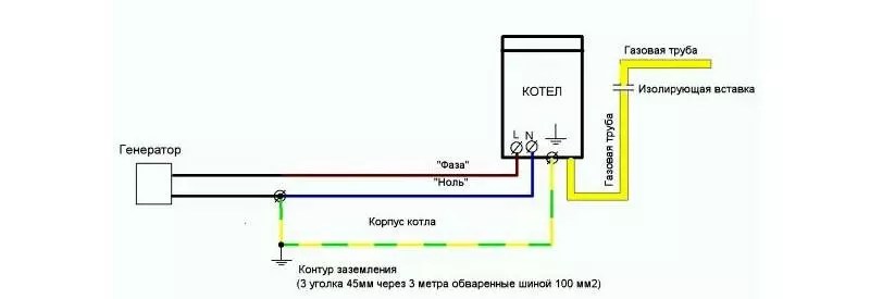
For you can use a homemade circuit, which we have already talked about or purchase a ready-made kit.
Note! A separate circuit for the boiler can be placed in the basement of the house. It will take only one square meter of area to install the structure.
Article
Recently, a lot of useful electrical appliances have appeared that make our life as comfortable as possible. For example, if gas is not supplied to your country mansion, then you can heat the premises using ceramic heaters, cook food on an electric stove, and install a boiler to heat water. But the more devices you use, the higher the likelihood of electric shock when in contact with them. To protect your life, you need to make grounding devices operating from the network. Unlike multi-storey buildings, the implementation of this electrical safety measure in a private house is not particularly difficult. Therefore, today we will talk about the grounding device, give its calculation and step-by-step installation instructions.
Purpose of protective earthing
A properly made ground loop in a private house will save you from electric shock when there is an insulation breakdown on the device case
When the insulation of the supply wire breaks down, a potential appears on the metal case of an ungrounded device. If you touch such a device, you can get an electric shock. At best, you will be “pinched” a little, and at worst, you will get serious injuries that are incompatible with life.
Why does a person get stressed? Current follows the path of least resistance. And he tends to the ground, because it has a large electrical capacity. Therefore, when in contact with a faulty device, your body (having a resistance of the order of 1 kOhm) becomes the only conductor. But what if we “offer” the current an easier path by connecting the equipment case to the ground with a metal conductor of less resistance? In this case, most of the charge will go through it.
In addition to ensuring safety, grounding allows you to:
- stabilize the operation of electrical installations;
- protect devices from power surges;
- reduce network interference, as well as the intensity of electromagnetic radiation of increased frequency.
Important: It is necessary to ground all consumers operating from networks with a voltage of more than 42 V AC and 110 V DC.
Device
The ground loop consists of two elements: the ground electrode itself and conductors. The latter are any parts of the device that connect electrical equipment to the circuit. As a rule, these are cables with yellow-green insulation and a busbar located in a switchboard (RShch). The grounding conductor includes electrodes and other circuit elements that are in direct contact with the ground and ensure the spreading of an electric charge.
Grounding conductors are natural and artificial. In the first case, the role of the grounding device is performed by the buried parts of the building structures of buildings, and in the second, a specially made conductor. According to the Electrical Installation Rules (PUE), preference should be given to natural grounding conductors. For example, in a private house it could be:
- well casing;
- metal pipelines;
- armor of power cables;
- all kinds of metal structures on the street, for example, a fence;
- buried reinforced concrete parts of the building (columns and foundations).
If the resistance of natural grounding conductors is less than the established norms, then it is allowed to use artificial ones. It is about them that we will talk today.
How to calculate
First of all, it is necessary to determine the conductivity of the ground electrode. That is, it is necessary to choose an electrode so that the resistance of the circuit is within the normal range. According to the provisions of the PUE, the maximum values of the spreading resistance of ground electrodes are as follows:
- 2 Ohm - for line voltage 660/380 V of a three-phase / single-phase current source;
- 4 Ohm - for 380/220 V;
- 8 Ohm - for 220/127 V.
The conductivity of the protective structure depends on the area of its contact with the ground, as well as the resistivity of the soil. The larger the pins (electrodes), the larger their surface area and, consequently, the higher the conductivity and efficiency of the circuit. At the same time, to achieve good characteristics of the grounding device, it is more correct to increase the length of the electrodes, and not the cross section. This is very important when creating contours in hard soils such as sandstone, rocky ground and others.
So, to determine the conductivity of one electrode of circular cross section, the following formula is used:
R1 = ρ(ln(2L/d) + 0.5ln(4T+L)/(4T-L))/2ПL,
where d and L are the diameter and length of the electrode, T is half the depth of the pin, ln is the natural logarithm, P is a constant (3.14), ρ is the resistivity of the soil (Ohm × m).
Soil resistivity is also an important parameter. The larger it is, the worse the conductivity of the ground loop will be. The value of resistivity for a certain type of soil can be found in publicly available tables.
The lower the soil resistivity, the better the contour will be
This is interesting: With the onset of cold weather, the resistance of the earth increases sharply. The reason for this is frozen water, because ice is a dielectric. Therefore, in areas with permafrost soils, the depth of grounding should be greater than in latitudes with a warmer climate.
When installing a ground loop consisting of several electrodes, the calculation changes slightly. First, the resistance of each individual pin is determined using the above formula. Then the obtained indicators are summed up taking into account the so-called "utilization rate". The calculation formula here is:
R = R1/(KN), where R is the total loop resistance, N is the number of electrodes, K is the utilization factor, R1 is the resistance of one pin.
The value of K depends on the distance between the electrodes. Moreover, the further apart the pins are located, the greater this coefficient will be. Electricians also recommend placing the electrodes at a distance of 2.2 of their length. In this case, K can take the following values:
- when using two electrodes - 0.9–0.92;
- three - 0.85–0.88;
- five - 0.79–0.83.
To determine the depth of the bars, you need to use the formula:
N = R1 / KR, where R is the previously obtained design resistance of the circuit, R1 is the resistance of one pin, K is the utilization factor.
As for the horizontal parts connecting the pins into one ground loop, their conductivity is not calculated here.
Choosing a contour scheme for a private house
The ground loop, made according to the "triangle" scheme, is the most reliable
There are many schemes of ground loops, and the most popular of them is the arrangement of electrodes in a triangle (closed circuit). The pins are driven into the ground at three vertices of an equilateral figure and connected on top with a horizontal strip. The main advantage of such a scheme is that if one of the ground electrodes fails, the circuit will continue to function.
The pins can also be driven in one row (linear scheme). This option is used if one narrow strip of land is allocated for grounding installation. The stakes are interconnected by one or two metal tires. On the one hand, the installation of this scheme is much easier to perform, since there is no need to dig three trenches. However, this variation of the contour is less reliable. The fact is that if at least one horizontal jumper fails, the efficiency of the entire system deteriorates sharply.
The choice is yours, but of the two above schemes, it is better to give preference to a closed ground loop configuration. If you decide to make groundings in a linear pattern, then add several electrodes and horizontal stripes. This will increase the reliability of the circuit.
Materials and tools for self-production
Use rods made of materials with high electrical conductivity as electrodes
After completing the calculation and selecting the ground loop scheme, you can proceed to the purchase of materials. To create a structure with your own hands you will need:
- black steel rods with a diameter of 16 millimeters or more - vertical electrodes;
- steel strip (tire) with a section of 5 × 40 millimeters - a horizontal ground electrode;
- copper wire with a cross section of at least 10 square millimeters - connecting the circuit to the switchboard;
- bolts with a diameter of 10 mm;
- black exterior paint or mastic.
Important: Structural rebar is not suitable for use as earth rods. The fact is that the outer layer of such rods is red-hot, so the electric current is distributed unevenly over the cross section. And this, in turn, leads to the destruction of the metal. In addition, the reinforcement is subject to corrosion.
The quantity and dimensions of materials are selected in accordance with the calculated data.
In addition, we will need the following tools and equipment:
- shovel (development);
- welding machine (connection of circuit elements);
- grinder (cutting materials);
- pliers (bending a horizontal strip);
- a sledgehammer and a puncher, preferably with a special nozzle for rods (driving vertical electrodes).
Work progress (with photo)
Site selection and soil development
Dig trenches under the contour near the house. So, you do not have to dig a long trench to build
First of all, you need to choose a place where the ground loop will be located. To minimize the amount of work and the consumption of materials, the installation of a grounding device should be carried out near the house of the building.
After site selection, earthworks are carried out. We take a shovel and dig trenches. In our case, there will be three of them, that is, we make a contour according to the "equilateral triangle" scheme. The depth and width of the trench should be more than half a meter, and the length should correspond to the calculation. It is also necessary to dig a recess from the nearest vertex of the triangle to the force shield.
Assembling the ground loop
If the soil is not homogeneous, then use a hammer drill to drive in the pins.
- First, we prepare vertical ground electrodes. We cut them with a grinder in accordance with the calculated data. Then we grind the ends of the pins under the cone. This is done so that the electrode enters the ground more easily.
- Then we cut the steel strip. The length of each segment should be slightly longer than the side of the triangle (about 20–30 centimeters). It is advisable to bend the ends of the strips in advance with pliers for tight contact with the pins during welding.
- We take the prepared pins and hammer them into the vertices of the triangle. If the ground is sandy and the electrodes go in easily, then you can get by with a sledgehammer. But if the density of the soil is high or stones are often found, then you will have to use a powerful hammer drill or even drill wells. We hammer the rods so that they protrude above the base of the trench by about 20-30 centimeters.
- Next, we take a metal strip 40 × 5 millimeters and grab it by welding to the pins. As a result, you will get a contour in the form of an equilateral triangle.
- Now we make a contour approach to the building. For this we also use the strip. It must be taken out and fixed against the wall (if possible, near the switchboard).
Weld the bolt to the bus well, since the resistance of the ground loop depends on the quality of the contact
Helpful Hint: Protect welding seams from corrosion. Paint the connection points of the contour elements and the bus outlet at the building with black exterior paint. The remaining parts of the grounding device must not be painted over!
All welded joints must be painted, as these places are most susceptible to destruction.
After installing the protective grounding circuit of the house, we fill the trenches with homogeneous soil without construction debris and rubble. It is recommended to use dense homogeneous fine-grained compositions for these purposes.
Video instruction for installation of the ground loop
Shield connection
To connect the circuit to the electrical panel, you need to use a copper wire with a cross section of 10 square millimeters. Screw one end of it to the ground electrode terminal, and lead the other end into the building and screw it to the power shield. By the way, if the switchboard is located in the house, then the same strip can be used to establish grounding, and the bolted transition can be done already indoors.
In a private house, the ground loop is connected according to the TN-C-S or TT scheme
Here it is also worth paying attention to the connection diagram of the circuit to the shield. In private homes, power is often provided by overhead lines (VL) over the TN-C grounding system. In this circuit, the source neutral and the protective conductor are combined. That is, a phase wire (L) and a combined "zero" and "ground" (PEN conductor) are suitable for the shield. Therefore, when connecting the circuit to the electrical installation, the TN-C system must be converted to TN-C-S, in which the PEN conductor is divided into zero working (N) and zero protective (PE) conductors. In this case, three wires will already come to the consumer: “phase”, separately “zero” and “ground”.
But how to connect a house to a grounding device using the TN-C-S system? This is done quite simply. To get a three-core electrical wiring with a separate protective conductor, you need to perform the following steps in the switchboard:
- Install a metal bus in the shield (you can buy it at any electrical supply store). Then connect it with a copper wire to the RSH housing. This will be the PE ground bus.
- We connect the combined PEN conductor coming from the power source to the PE bus.
- Then we make a jumper between the ground bus and the zero working conductor N, the bus of which must be isolated from the switchboard.
- At the end, we connect the phase wire to a separate bus, which is also not connected to the RSH case.
You can connect the building to the circuit in another way - using the TT system. In this case, you do not need to share anything. The phase wire is connected to an isolated bus, and the combined PEN conductor from the power source sits on a second separate bus and is considered "zero". Well, the shield body is connected to a grounding device. Thus, when connecting the circuit according to the TT scheme, it is not electrically connected to the PEN conductor. The only drawback of such a connection is the need to install additional protective devices, such as an RCD.
Earth resistance measurement
The measurement of the spreading resistance of the ground electrode is carried out by means of a verified instrument F4103-M1
After installing and connecting the circuit, it is imperative to check whether it will protect you from electric shock. To do this, it is necessary to measure the resistance of current spreading and metal bonding.
As noted earlier, in accordance with PUE 1.7.101, the resistance of the grounding device at any time of the year should not exceed 2, 4, 8 Ohms at line voltages of 660, 380, and 220 V of a three-phase current source or 380, 220 and 127 V of a single-phase current source . To measure the resistance of the circuit, you need a special device F4103-M1. It is expensive, so it makes no sense to buy it. It is much easier to invite employees from the energy department or electrical laboratory, who will take measurements and issue a passport and a protocol for the grounding device. If the resistance of the circuit exceeds the norm, then additional pins will have to be driven in.
Measuring the resistance of a metal bond allows you to determine the presence of a circuit between grounding and grounding elements. This parameter is measured with an F4104-M1 microohmmeter. In accordance with PTEEP clause 28.5, the contact resistance should not be more than 0.05 Ohm. If the resistance of the metal connection is above the norm, then all bolted and welded connections of the circuit elements will have to be checked.
As for the frequency of checking the condition of grounding devices, it is determined by the schedule of preventive maintenance. It is approved by the technical head of the consumer. In accordance with clause 2.7.9. PTEEP, visual inspection of the outer parts of the ground electrodes must be carried out at least once every six months. A survey with a selective opening of the earth - once every 12 years.
Important: The loop resistance must be below normal all year round, so it is advisable to check the ground electrode during drought or frost (when the soil resistivity increases).
The most common mistakes when doing work
Mistakes that should not be made when arranging a protective ground loop in a private house:
- If you decide to seek help from installers, then you need to make sure that they use only suitable materials. The fact is that many organizations are trying to save on electrodes and dig pins with low conductivity into the ground, for example, rusty fittings. And this, as you already know, greatly worsens the protective properties of the circuit or even makes it useless.
- Grounding device at a great distance from the building. The circuit does not pose a danger to humans, so it should be installed closer to home. And it is desirable that the ground electrode is located in the wettest place. After all, water improves conductivity, which leads to a faster circuit closure and instantaneous operation of protective equipment.
- Connection of the ground loop with lightning protection. If your switchboard does not have an SPD device that opens the circuit in the event of an overcharge, then a large current from the lightning rod can damage the electrical equipment or the switchboard itself.
The protective ground loop is a mandatory safety measure when using electrical appliances in a private house. If you decide to do the grounding yourself, then do all the work in accordance with the above rules and recommendations. At the same time, do not forget about safety precautions when working with welding and power plants.


