Living in a country house gives you not only many advantages over the bustle of the city, but also a number of problems that have to be solved to ensure the necessary comfort. One of these problems is the arrangement of the water supply system in conditions where you cannot connect to centralized water supply networks. In this case, the only way out is to dig a well or drill a well. However, in order to organize an uninterrupted automatic supply of water from a source to the house, you will need pumping equipment, which many owners can install and connect on their own. To do this correctly, you need to know the connection diagram of the borehole pump and understand the intricacies of the process.
Pump selection
Before considering the connection diagram of pumping equipment, it is necessary to choose the right unit. All pumps can be divided into two types:
- Submersible units. These pumps work below the surface of the water and push water from a well or well in a country house up through a piping system or hose.
- Surface type devices are installed on the surface and pump water out of the hydraulic structure.
Submersible pumping equipment has a number of advantages over surface products:
- Since the unit works underwater in the depth of the well, the noise from its operation is practically not audible on the surface.
- For the same reason, the product saves space on the site. In addition, for the installation of the unit, it is not necessary to allocate a separate room or equip a caisson.
- During the operation of a well pump, less electricity is consumed than during the operation of a surface product.
In turn, submersible pumps can be divided into several groups:
- deep well units, which are divided into two subspecies vibratory and centrifugal;
- drainage pumps;
- circulation pumping equipment;
- fountain units.
By the name, you can guess that for the arrangement of the water supply system, the installation of a deep downhole pump product is required. We will consider the connection diagram of such a pump in our article.
Important: a deep unit can lift water from a great depth (up to 100 m) and supply it to the water supply pipes of the house. At the same time, most models easily cope with the pumping of water containing a small amount of impurities in the form of particles of clay and sand.
Before proceeding to the connection diagram, it is worth figuring out whether we need a vibration or centrifugal type of product. So, vibration pumping equipment is suitable for shallow wells. This is an inexpensive equipment that can pump even very polluted water. But its disadvantage is that the vibrations during the operation of the pump can destroy the hydraulic structure. Centrifugal units are more productive, safer and more durable, which is why they are most often used to connect to the water supply system of a country house.
Optional equipment

A direct scheme for connecting the unit to the network without the use of auxiliary equipment looks quite simple and is performed by connecting the pumping equipment to the contact group. However, this connection scheme may not be used in all cases. Moreover, most often the connection of a submersible borehole pump is done using automation. This facilitates the maintenance of the water supply system, increasing its performance. As a rule, the list of used automation includes the following elements:
- electric starters;
- intermediate relay (switches);
- pressure and liquid level control sensor;
- hydraulic tank
Purpose of automation

Thanks to the use of automation when installing downhole pumping equipment, it is possible to achieve automatic operation of the water supply system. The fundamental element of this system is a contactor with an open contact group. The supply conductors are fed to the input of the contactor, and a pump for the well is connected to the output.
In such a connection scheme, a hydraulic accumulator must be used, which is complemented by a check valve. A pressure switch is being installed next to the hydraulic tank, without which it is impossible to imagine the automation of pumping equipment. The relay controls the contact group and ensures the start and stop of pumping equipment when the pressure rises or falls to a predetermined level in the water supply system.
Automation for a borehole pump works according to the following principle:
- When the pressure in the system drops to the set minimum, the relay sends a signal to turn on the pumping equipment. At this moment, the contacts of the working group are closed, and the power supply of the pump is turned on.
- As a result of filling the system with water, the pressure in the hydraulic tank gradually increases.
- When the pressure reaches the set maximum, the relay sends a signal to the contactor. As a result of this, the contacts open the circuit, and the pumping equipment is automatically disconnected from the power supply.
For water supply systems that work with significant volumes of liquid, it is not electrical automation that is more suitable, but float sensors that automatically control the water level in the storage tank - the hydraulic tank. In principle, this scheme for connecting pumping equipment does not differ from systems using automation. The only difference is that instead of a pressure switch, a level sensor is installed here.
Important: to connect to a submersible well pump, special waterproof cables of the KVV or VPP brand are used. Instead, you can take an imported product labeled AQUA RN8.
The purpose of the accumulator

The principle of operation of the submersible unit involves its launch at the time of pressure reduction in the plumbing system. However, frequent opening and closing of taps in the house will lead to frequent starting and stopping of pumping equipment. Since the pump creates a sufficiently strong pressure even when the tap is open, the unit may automatically turn off. As a result of this mode of operation, pumping equipment will quickly wear out and fail. To protect the engine from frequent starting due to pressure drops, the pump unit is connected via a hydraulic tank.
Hydraulic accumulator- This is a steel sealed container, inside of which there is a rubber pear. The wall of the pear, like a membrane, divides the cavity of the tank into two chambers: inside the first chamber (pear) there is water, and in the second chamber (in the space between the walls of the pear and the body) air is pumped. The pump pumps water into the pear until the air pressure balances the water pressure. If any faucet is opened in the system, the air will push water into the pipes.
Some hydraulic accumulators are made in the form of a container, divided into two parts by a rubber membrane, and not with a pear in the middle. Air is in one part of the tank, water is pumped into the other. The principle of their work is the same. The volume of the hydraulic tank depends on the number of inhabitants in the house and the water consumption. For an average country house, a 100-liter tank is enough.
The main purpose of the hydraulic tank:
- it maintains the pressure in the system at the desired level;
- a certain amount of water is stored in the tank;
- the hydraulic accumulator reliably protects the water supply system from water hammer.
Important: thanks to the hydraulic tank that maintains the set pressure, pumping equipment is started less often, which reduces engine wear and prolongs the life of the product.
Connection

To connect a borehole pump, you will need the following components:
- hydraulic tank of appropriate capacity;
- pressure switch suitable for the selected type of hydraulic tank;
- transitional inch coupling-American;
- coupling with collet clamp;
- brass adapter;
- sealing tape;
- fitting;
- plastic water pipes.
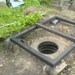
For the convenience of connecting automation to a borehole pump, a pit of concrete rings is equipped near the well or a caisson is mounted. Moreover, their bottom should be below the freezing level of the soil. It is more convenient to carry out work on assembling the control circuit of pumping equipment not in a caisson or pit, but on the surface. After assembly, the entire system is lowered to the bottom of the pit (caisson), where it is connected to the pump. Automation assembly work is carried out in the following sequence:
- First, the accumulator is tied. FUM tape is used to seal all connections.
- Then a pressure switch is connected to the accumulator. In this case, the connection is not made directly, but through an American adapter. This allows you to easily dismantle the product if necessary, and also simplifies setup and connection operations. A special gasket is used to seal the connection of the relay with the strapping.
Important: install the pressure switch in such a place that you can take readings from the pressure gauge without sinking to the bottom of the pit or caisson.
- In order to connect the water supply to the outlet coming from the pressure switch, it is necessary to make a prefabricated elbow. It is soldered from a piece of plastic pipe and a fitting. At the end of the plastic pipe, a coupling with an MPH thread is soldered. It must be hermetically attached to the tap from the relay.
As for the pumping equipment itself, its installation takes place in the following sequence:
- Before the node where the pressure switch with a hydraulic accumulator is mounted, a coarse filter must be installed. It is advisable to install the same filter on a section of the pipeline running from the accumulator to the entrance to the house. However, this is not required.
- The sequence of connecting the wires can be viewed on the electrical diagram of the pumping equipment. The length of a submersible cable with reliable grounding, which provides power to the pump, is determined taking into account the dynamic level of immersion of the pumping unit plus the length from the well to the installation site of the control panel.
- The cable is soldered to the pumping equipment, and the insulation is carried out using a heat-shrinkable fluid coupling.
- The pump is connected to the water supply pipe through the barrel, check valve and fitting.
- Pumping equipment on a steel cable is suspended in the well so that the unit does not approach the bottom of the hydraulic structure by more than 1 m.
- A cap is mounted on the well.
