This DIY circuit can be used as a speed controller for a 12V DC motor with a current rating of up to 5A, or as a dimmer for 12V halogen and LED lamps up to 50W. Control is carried out using pulse width modulation (PWM) at a pulse repetition rate of about 200 Hz. Naturally, the frequency can be changed if necessary, selecting for maximum stability and efficiency.
Most of these structures are assembled at a much higher cost. Here we present a more advanced version that uses a 7555 timer, a bipolar transistor driver and a powerful MOSFET. This design provides improved speed control and operates over a wide load range. This is indeed a very effective scheme and the cost of its parts when purchased for self-assembly is quite low.
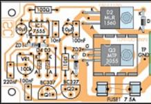
The circuit uses a 7555 Timer to create a variable pulse width of about 200 Hz. It controls transistor Q3 (via transistors Q1 - Q2), which controls the speed of the electric motor or light bulbs.


There are many applications for this circuit that will be powered by 12V: electric motors, fans or lamps. It can be used in cars, boats and electric vehicles, in model railways and so on.

12 V LED lamps, for example LED strips, can also be safely connected here. Everyone knows that LED bulbs are much more efficient than halogen or incandescent bulbs and will last much longer. And if necessary, power the PWM controller from 24 volts or more, since the microcircuit itself with a buffer stage has a power stabilizer.
Any modern power tool or household appliance uses a commutator motor. This is due to their versatility, i.e. the ability to operate on both alternating and direct voltage. Another advantage is the efficient starting torque.
However, the high speed of the commutator motor does not suit all users. For a smooth start and the ability to change the speed of rotation, a regulator was invented, which is quite possible to make with your own hands.
Operating principle and types of commutator motors
Each electric motor consists of a commutator, stator, rotor and brushes. The principle of its operation is quite simple:
In addition to the standard device, there are also:

Regulator device
There are many schemes of such devices in the world. Nevertheless, they can all be divided into 2 groups: standard and modified products.
Standard device
Typical products are distinguished by ease of manufacture of the idynistor and good reliability when changing engine speed. As a rule, such models are based on thyristor regulators. The operating principle of such schemes is quite simple:

Thus, the speed of the commutator motor is adjusted. In most cases, a similar scheme is used in foreign household vacuum cleaners. However, you should know that such a speed controller does not have feedback. Therefore, when the load changes, you will have to adjust the speed of the electric motor.
Changed schemes
 Of course, the standard device suits many fans of speed controllers to “dig” into the electronics. However, without progress and improvement of products, we would still be living in the Stone Age. Therefore, more interesting schemes are constantly being invented, which many manufacturers are happy to use.
The most commonly used are rheostat and integral regulators. As the name implies, the first option is based on a rheostat circuit. In the second case, an integral timer is used.
Rheostatic ones are effective in changing the number of revolutions of the commutator motor. High efficiency is due to power transistors, which take part of the voltage. Thus, the current flow is reduced and the motor works with less effort.
Video: speed control device with power maintenance
The main disadvantage of this scheme is the large amount of heat generated. Therefore, for smooth operation, the regulator must be constantly cooled. Moreover, the cooling of the device must be intensive.
 A different approach is implemented in an integral regulator, where an integral timer is responsible for the load. As a rule, transistors of almost any type are used in such circuits. This is due to the fact that it contains a microcircuit with large output current values.
If the load is less than 0.1 ampere, then all the voltage goes directly to the microcircuit, bypassing the transistors. However, for the regulator to operate effectively, it is necessary that there be a voltage of 12V at the gate. Therefore, the electrical circuit and the supply voltage itself must correspond to this range.
Overview of typical circuits
 You can regulate the rotation of the shaft of a low-power electric motor by connecting a power resistor in series with no. However, this option has very low efficiency and the inability to smoothly change speed. To avoid such a nuisance, you should consider several regulator circuits that are used most often.
As you know, PWM has a constant pulse amplitude. In addition, the amplitude is identical to the supply voltage. Consequently, the electric motor will not stop even when running at low speeds.
The second option is similar to the first. The only difference is that an operational amplifier is used as the master oscillator. This component has a frequency of 500 Hz and produces triangular-shaped pulses. Adjustment is also carried out using a variable resistor.
How to make it yourself
 If you don’t want to spend money on purchasing a ready-made device, you can make it yourself. This way, you can not only save money, but also gain useful experience. So, to make a thyristor regulator you will need:
- soldering iron (to check functionality);
- wires;
- thyristor, capacitors and resistors;
- scheme.
As can be seen from the diagram, the regulator controls only 1 half-cycle. However, for testing performance on a regular soldering iron, this will be quite enough.
If you don’t have enough knowledge to decipher the diagram, you can familiarize yourself with the text version:

The use of regulators allows for more economical use of electric motors. In certain situations, such a device can be made independently. However, for more serious purposes (for example, monitoring heating equipment), it is better to purchase a ready-made model. Fortunately, there is a wide selection of such products on the market, and the price is quite affordable.
A high-quality and reliable rotation speed controller for single-phase commutator electric motors can be made using common parts in literally 1 evening. This circuit has a built-in overload detection module, provides a soft start of the controlled motor and a motor rotation speed stabilizer. This unit operates with voltages of both 220 and 110 volts.
Regulator technical parameters
- Supply voltage: 230 volts AC
- regulation range: 5…99%
- load voltage: 230 V / 12 A (2.5 kW with radiator)
- maximum power without radiator 300 W
- low noise level
- speed stabilization
- soft start
- board dimensions: 50×60 mm
Schematic diagram
 Scheme of motor regulator on a triac and U2008
 The control system module circuit is based on a PWM pulse generator and a motor control triac - a classic circuit design for such devices. Elements D1 and R1 ensure that the supply voltage is limited to a value that is safe for powering the generator microcircuit. Capacitor C1 is responsible for filtering the supply voltage. Elements R3, R5 and P1 are a voltage divider with the ability to regulate it, which is used to set the amount of power supplied to the load. Thanks to the use of resistor R2, which is directly included in the input circuit to the m/s phase, the internal units are synchronized with the VT139 triac.
 Printed circuit board
 The following figure shows the arrangement of elements on a printed circuit board. During installation and startup, attention should be paid to ensuring safe operating conditions - the regulator is powered by a 220V network and its elements are directly connected to the phase.
Increasing regulator power
In the test version, a BT138/800 triac with a maximum current of 12 A was used, which makes it possible to control a load of more than 2 kW. If you need to control even larger load currents, we recommend installing the thyristor outside the board on a large heatsink. You should also remember to select the correct FUSE fuse depending on the load.

In addition to controlling the speed of electric motors, you can use the circuit to adjust the brightness of lamps without any modifications.
You can adjust the rotation speed of the shaft of a low-power commutator motor by connecting it in series to its power supply circuit. But this option creates a very low efficiency, and in addition there is no possibility of smoothly changing the rotation speed.
The main thing is that this method sometimes leads to a complete stop of the electric motor at low supply voltage. Electric motor speed controller The DC circuits described in this article do not have these disadvantages. These circuits can also be successfully used to change the brightness of 12-volt incandescent lamps.
Description of 4 electric motor speed controller circuits
First scheme
The rotation speed is changed by variable resistor R5, which changes the duration of the pulses. Since the amplitude of the PWM pulses is constant and equal to the supply voltage of the electric motor, it never stops even at a very low rotation speed.
Second scheme
It is similar to the previous one, but the operational amplifier DA1 (K140UD7) is used as the master oscillator.

This op-amp functions as a voltage generator producing triangular-shaped pulses and having a frequency of 500 Hz. Variable resistor R7 sets the rotation speed of the electric motor.
Third scheme
It is unique, built on it. The master oscillator operates with a frequency of 500 Hz. The pulse width, and therefore the engine speed, can be changed from 2% to 98%.

The weak point in all the above schemes is that they do not have an element for stabilizing the rotation speed when the load on the DC motor shaft increases or decreases. You can resolve this problem using the following diagram:

Like most similar regulators, the circuit of this regulator has a master voltage generator that produces triangular pulses with a frequency of 2 kHz. The entire specificity of the circuit is the presence of positive feedback (POS) through elements R12, R11, VD1, C2, DA1.4, which stabilizes the rotation speed of the electric motor shaft when the load increases or decreases.
When setting up a circuit with a specific motor, resistance R12, choose a PIC depth at which self-oscillations of the rotation speed do not occur when the load changes.
Parts of electric motor rotation controllers
In these circuits, it is possible to use the following replacements of radio components: transistor KT817B - KT815, KT805; KT117A can be replaced with KT117B-G or 2N2646; Operational amplifier K140UD7 on K140UD6, KR544UD1, TL071, TL081; timer NE555 - S555, KR1006VI1; microcircuit TL074 - TL064, TL084, LM324.
When using a more powerful load, the KT817 key transistor can be replaced with a powerful field-effect transistor, for example, IRF3905 or similar.
The PWM controller is designed to regulate the rotation speed of a polar motor, the brightness of a light bulb or the power of a heating element.
Advantages:
1 Ease of manufacture
2 Availability of components (cost does not exceed $2)
3 Wide application
4 For beginners, practice once again and please yourself =)
One day I needed a “device” to adjust the rotation speed of a cooler. I don’t remember why exactly. From the beginning I tried it through a regular variable resistor, it got very hot and this was not acceptable for me. As a result, after rummaging on the Internet, I found a circuit based on the already familiar NE555 microcircuit. This was a circuit of a conventional PWM regulator with a duty cycle (duration) of pulses equal to or less than 50% (later I will give graphs of how this works). The circuit turned out to be very simple and did not require configuration; the main thing was not to mess up the connection of the diodes and transistor. The first time I assembled it on a breadboard and tested it, everything worked within half a turn. Later I laid out a small printed circuit board and everything looked neater =) Well, now let’s take a look at the circuit itself!

PWM regulator circuit
From it we see that this is a regular generator with a pulse duty cycle regulator assembled according to the circuit from the datasheet. With resistor R1 we change this duty cycle, resistor R2 serves as protection against short circuits, since pin 4 of the microcircuit is connected to ground through the internal timer switch and when R1 is in the extreme position it will simply close. R3 is a pull-up resistor. C2 is the frequency-setting capacitor. The IRFZ44N transistor is an N channel mosfet. D3 is a protective diode that prevents the field switch from failing when the load is interrupted. Now a little about the duty cycle of pulses. The duty cycle of a pulse is the ratio of its repetition period (repetition) to the pulse duration, that is, after a certain period of time there will be a transition from (roughly speaking) plus to minus, or more precisely from a logical one to a logical zero. So this period of time between pulses is that same duty cycle.

Duty ratio at middle position R1
Duty cycle at leftmost position R1

Duty ratio at the extreme right position R
Below are printed circuit boards with and without parts locations


Now a little about the details and their appearance. The microcircuit itself is made in a DIP-8 package, small-sized ceramic capacitors, and 0.125-0.25 watt resistors. The diodes are ordinary 1A rectifier diodes (the most affordable is 1N4007; there are plenty of them everywhere). The microcircuit can also be installed on a socket if in the future you want to use it in other projects and not unsolder it again. Below are photos of the details.


