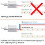
- Incorrect installation and connection with errors
Here are the main three rules and mistakes that you need to pay attention to first.
1 rule

The LED strip is connected in parallel, in sections of no more than 5 meters each.
It is even sold in reels of this meter. What if you need to connect 10 or 15m? It would seem that you connect the end of the first piece with the beginning of the second and you're done. However, such connection is prohibited. Why is this so accepted?
Because five meters is the estimated length that the current-carrying tracks of the tape can withstand. With a longer length, the load will exceed the permissible one and the tape will definitely fail. In addition, uneven glow will be observed. At the beginning of the strip, the LEDs will shine brightly, and at the end they will be much dimmer.
This is what a parallel connection diagram for LED strips with a length exceeding the permissible length will look like: 
In this case, the tape can be connected both from two sides and from one. Connecting on both sides allows you to reduce the load on the current paths, and also helps to avoid uneven glow at the beginning and end of the tape. 
This is especially important on a powerful tape - over 9.6 W/meter. This is exactly how professionals who have been installing LED products for many years advise connecting. The only big drawback is that you have to drag additional wires along the entire lighting.
Rule 2

The LED strip must be mounted on an aluminum profile, which acts as a heat sink.
During operation, the tape heats up, and this temperature negatively affects the LEDs themselves. They simply overheat and begin to lose brightness, gradually degrading and collapsing.
Thus, a tape that could easily work for 5-10 years without a profile will burn out in a year, and maybe even earlier. Therefore, the use of aluminum profiles in LED lighting is mandatory. 
The only tape where you can do without it is SMD 3528. It is low-power, only 4.8 W per 1 m and is not so demanding on heat dissipation. 
Tapes filled with silicone on top especially need heat removal. In them, heat transfer occurs only through the substrate, from below. And sometimes this is not enough. If you also stick it on some kind of plastic or wood, then there will be no cooling at all.
Rule 3
 The correct choice of power supply is a guarantee of long-term and safe operation of the entire backlight.
The power supply must be 30% more powerful than the LED strip.
Only in this case will it work normally. If you select it closely, exactly according to the power of all LEDs, then the unit will constantly work at its limit. Naturally, such work will affect the duration of operation. So always give him some extra.
Connecting LED strip
To install lighting using LED strip you will need:


Installation of 220V power supply
If you have not completed electrical installation work, then you must first supply 220V voltage to the connection point of the tape. To do this, ditch the wall, or lay a cable channel and stretch a three-core VVGng-Ls 3*1.5 cable along it. Lead it directly to the distribution box where the power supply for the LED strip will be connected. 
You can use the existing junction box where the main lighting is connected. The main thing is that the space allows you to freely connect additional wires and terminal blocks.
It is advisable to install the switch on the LED strip on the 220 Volt wires, and not in front of the strip on the outgoing 12-24V. In this case, the unit will not work continuously. Moreover, it is contraindicated for pulse units to operate without load. In addition, this will increase the level of security. 
Pre-check and do not confuse phase, neutral and ground. Most often, the neutral is blue, the grounding conductor is yellow-green, and the phase conductor is of any other color.
But you can’t trust color coding alone! More details on how to distinguish zero and phase without errors can be found in the article “How to determine phase and zero in electrical wiring.” 
Next, you need to lay a cable from this junction box in a groove, corrugated sleeve or in a cable channel to the future location of the power supply. To place it, install a convenient shelf. It can be made from pieces of plywood or drywall. Place a dimmer nearby. 
Connecting the power supply
Having stretched the cable to the block, you can proceed directly to connecting the wires.
- connect the phase wire to connector L
- blue wire - zero, to terminal N
- yellow-green - to the terminal marked as Pe or with a ground symbol
Dimmer connection
Now you need to connect the dimmer. Here use flexible mounting wire PuGV 1.5mm2 in different colors. For example, black (for negative contacts) and red (for positive ones).
- measure and cut the required wire size
- clean the ends and crimp them with NShVI tips
 First of all, connect the ends from the power supply side. Connect the negative wire (black) to the terminal marked –V. Positive wire (red) with terminal marked as +V.
Both wires must be connected to the dimmer side Power IN(input power). Connect the red wire on the dimmer to the positive terminal DC+, and the other wire to the minus terminal DC-
Next comes the installation work of laying the wire again. Stretch it in a corrugation from the dimmer to the point of connection to the LED strip. Use the same PuGV. If the total length of the LED strip and backlight exceeds 5 meters, the strips are connected in parallel. Moreover, each of them is supplied with separate power. 
Proceed to connect the wires to the dimmer terminals. They usually have an inscription and are designated as Output Led. For reliable contact, it is better to crimp the stripped ends of the cores with tips. 
Installation and soldering of wires on LED strip
You can proceed to installing the tape itself. To do this, you need to measure it and cut it into the required pieces. This can not be done in any place, but only where the dotted line is applied or scissors are drawn. 
After cutting, the wires can be soldered to special contacts on the tape. For the same purposes, as well as for connecting individual pieces of tape to each other, connectors can be used. 
Look for the negative terminal and connect black wires there. Accordingly, another wire goes to the plus contact - red. Do not heat the soldering iron to maximum, otherwise you will easily burn the substrate. Recommended soldering time is up to 10 seconds. 
The opposite ends are also cleaned and NShVI tips are installed on them. 
Remember once again that for better cooling, you only need to lay the LED strip on an aluminum profile. It is installed in advance.
After all this work, all wire strands are brought out to one place and connected to the corresponding supply wires, observing the phasing (positive and negative contacts). 
Connections are best made using Wago terminals.
About the design of an LED strip with a touch switch: pros, cons. We assemble an LED strip with a touch switch ourselves. 5 questions you need to understand. + TEST for self-test
TEST:
4 questions to test your knowledge- What is the assembly formed from?
B. Switch.
B. Wiring.
G. Nutrition.
- What type of button is right for the switch?
A. Infrared.
B. Dimmer.
B. Sensory.
G. The most common one.
- Adapter power supply.
- Why do you need a plastic profile?
A. Beauty.
B. Ease of installation.
B. Security of the system.
G. Not needed at all.
Modern interior solutions often use electrics with motion sensors. It would be more correct to call them touch radio switches. Let us consider in detail the advantages, areas for proper use and much more.
3 pluses and 1 minus
U LED lighting 3 advantages:
- efficiency.
- impressive service life.
- The service life is not affected by the number of switching on and off.
They have only one drawback - the high price.
Typically, such lighting is located in the kitchen. The location areas are as follows:
- Functional. 1 Solid LED Light with Touch Switch for Kitchen under the cabinets. Look at the picture:
The most powerful is required here lighting. Because the work area is the most popular area for the housewife. Such lighting will save your eyes and improve the level of cleanliness.
- In the hood above the stove. Although there is usually an integrated backlight.

- Lighting glass furniture. Look at the picture:

Very beautiful, convenient for furniture use. Advantageous in terms of electricity consumption. In general, you don’t have to turn it off, but it’s great if such lighting turns on automatically.
- Above the upper furniture.
- Below the bottom line of cabinets. Look at the picture:

Light source It's better to hide it carefully. Here a thin and almost invisible LED Strip Light. Any warm shade will do.
- Under the countertop. Look at the picture:

Here ribbon follows along the front side of the lower furniture. Ideal for a pull-out cabinet, serving utensils in the evening.


The LED strip in the kitchen can be placed anywhere. It all depends on your budget and imagination.
More about LED strip (hereinafter referred to as S.L.): 3 main points
Ribbon It can be either ready-made or homemade. Its types:
- Invoice. Variety - linear. Can be purchased as a set or individually. In the set, the modules are connected into one complex by a special adapter.
- Invoice. Variety - dotted. Look at the picture:

Today you can buy items 1 and 2, which already have built-in touch switches. It is enough to lightly touch their body in a certain area to turn the light on or off.

Usually looks like a constantly lit blue LED.
- Mortise tape. It can also be linear or pointwise. A good advantage is the thickness. Mortise installation tapes usually occurs in the bottom shelf of the cabinet towards the bottom surface.

This lighting fits entirely into the bottom shelf. Installation requires certain skills.
Independent creation of backlight from S.L.: taking into account 4 schemes
LED strips popular for the following reasons:
- Huge range of colors and brightness.
- The tape can be cut to the desired length.
- Prices are more modest than those of ready-made devices.
Look at the picture for an example of a tape:

To assemble a working light device from a strip, you need the following materials:
- Ribbon required length.
- Aluminum guide (profile). Look at the picture:

The backlight will have a very neat appearance if installed in a profile like this. And this will make it easier during the final installation.
- 12 W adapter.
- Switch.
5. Electrical cable and plug. Instead, you can use a terminal block. The type of connection matters here. The most suitable cable: made of copper, with a large number of cores, in double braid. Its minimum cross-section: 2 x 0.75 sq. mm.
- Thermal shrink tube. It seals all connections.
Need to know! Often the tape can be purchased in a kit with an adapter and control.

For tapes Any room with high humidity needs protection from evaporation. Lowest degree of protection - IP44(copes with droplets). More solid level - IP65(copes with the stream). The safest setting is 12 W.
The workspace should be illuminated as much as possible. Therefore it is better to use tape from 3- SMD crystal diodes 50x50. 30 diodes are formed. The formula works: 1 m – 12 lumens. If you need brighter lighting, it is better to use the 60 diode version. The color temperature is in the range 3300 – 500 K.
Auxiliary lighting can do without high brightness. SMD 35x28 parameters are enough. 1 m - 5 lumens. Color is not particularly important here. It is more determined by the design concept.
Below is a table of parameters of suitable tapes:
For stable operation of the backlight, you need an adapter with an approximate power reserve of 25%. The power of the tape is affected by the type of model. A store consultant can advise on technical aspects so that connecting 1 touch switch to the LED strip was successful.
For example, the SMD 50x50 version consumes 7.2 W per meter. Then, with a length of 4 m, the total power reaches 28.8 W. You will need a 36 W adapter.
Suitable switches:
- Regular with button format.
- Sensory.
- Infrared.
- Dimmer. Mechanical or sensory.
- A control unit that causes the light to blink or have an elegant color shift. This works if an RGB strip is used.
If several SLs become the basis for illumination, then the assembly of the device proceeds according to the following plan (parallel):

It is important to follow the assembly rules:
- The tape is cut only in specific places. They are specially marked.
- You can use several tapes.
- The cable coming from the block is soldered to the tape. The contact area is sealed - crimped with a thermal shrink tube.
The soldering algorithm is presented schematically below:

A regular switch should be placed before the adapter, based on this diagram:

The dimmer and RGB block are installed only after the adapter. Scheme:

The lighting is mounted under the cabinets. An adhesive tape that is sticky on both sides helps with this. First, it is conditionally attached in several areas. After making sure that it is placed in the desired area and evenly, press it along its entire length.
Important! If you lack knowledge in this area, contact the experts.
DIY LED lighting for the kitchen work area
Touch switches (S.V.): 1 switch for everything
Switches of this type have not been on the market for long, but have already become very popular. Often Sensor switch Already running in a duet with a ribbon.
First you need to find out what it is sensor. Its appearance is a panel made of crystals. There is a special marking on it. Household versions are designed for a 220 V system.
Such devices are excellent solutions for installing in the kitchen using LED strips. This way the functional surface is illuminated powerfully and efficiently. A switch attached to the strip greatly facilitates work in the evening and at night. But for problem areas, the following remote control was invented:

You can connect sconces to such a switch. It also helps control lighting in multi-tiered ceilings. Of course, if a ribbon with one color or a multi-colored palette is used. This system is convenient to control using the remote control.
No matter how the switch is used, it should be borne in mind that the connection plan may be different.
Some changes appear in the circuit when the remote control is used.
Sensor switch It’s not difficult to buy in a store, but you can create it yourself. Self-installation of such a switch is not difficult. Work can be carried out in the kitchen or in another room. For installation in the kitchen, an aluminum profile should be used.
Variations: 3 ways
The switch may become active. Turn on lighting from various touches. The device can respond to:
- Close proximity to the sensor.
- Finger contact with the touch console. This is the most famous option.
- Changes in temperature indicators.
The device can also be activated by sound or at a designated time, and if movement appears within its range of action.
Additional sensor functionality: 5 important points
This device has a variety of activations. It may also have additional features. With certain skills, a homemade sensor can be equipped with a good range of functions. Today similar switches are released with the following versions of added functions:
- Remote control. It greatly facilitates control over the light spectrum of multi-color tape. In this case, the use of a controller is mandatory. Otherwise the remote control will not work. The remote control is also good at controlling sconces. And when connecting to a tape, the remote control must be selected in tandem with the controller.
- Timer. Thanks to this device, significant energy savings can be achieved. In the timer, you can set the time to turn off the lights when there are no people in the room or in the house.
- Volume response. This product reacts even to light contact. Often this device is made independently and complements the timer.
- View without contact. The reaction of these devices occurs when the situation in the room somehow changes. These may be different movements, temperature and lighting changes.
- Dimmer. Any designated touch strip devices can be equipped with a dimmer. This addition allows you to control the brightness of the light in the room.
Optimal for a residential apartment is 1 netxt LED light with touch switch. But it is not prohibited to work on modern electrics with your own hands. More on this below.
What is the structure of September off: 4 main points
To assemble it yourself switch with sensor, and then install it correctly using a suitable profile, you need to know its structure and algorithm of action.
Whatever type of device you use to connect to the tape, this will not affect the algorithm of their operation in any way.
And in any modification there are four components:
- Front side. This is the outer part of the device. In some cases, lighting may be installed behind it.
- Touch indicator. Its type determines what its reaction will occur to.
- Switching diagram. Thanks to it, the signal is converted into current. Otherwise, it already activates the lighting equipment connected to it (this could be a tape or other light source).
- Frame. They can be integrated or overhead. Depending on its type, the type of installation work is determined. The housing can be installed directly inside the wall, or it can simply be superimposed.
The duration of its operation also depends on the quality of all components of the device. Therefore, it is important to select modifications that have optimal proportions of cost and quality.
Touch device externally it is a module. This device is quite compact. For this reason, it can be simply mounted into an aluminum profile. Thanks to this profile, the switch can be positioned next to the tape (or other light source).
During the installation process, it should be taken into account that the housing reacts to various touches very quickly. Therefore, contact with the device must be made only at one point. In the intended installation area, any unintentional interference with the sensitive housing console is completely excluded.
It is better to connect the device according to the proposed scheme:

Follow it strictly and connect the device correctly and quickly.
Independent assembly process according to 1 scheme
Skills in working with a soldering iron and good knowledge of electronics are required here. All components of the structure must also be present. Only under such conditions can you make a high-quality switch yourself. Then connect it to the desired tape.
It must be designed to operate from a household system - 220 V. The most difficult and important aspect here is the correct soldering of the required circuit.
Below is the simplest version of the scheme. Even a novice shareholder can master it.
Note: in the second scheme, you can refuse to use a capacitor.
Scheme
The parts needed for the job are:
- A pair of transistors. Type - KT315.
- Resistance. Parameter -30 Ohm.
- Semiconductor. The required type is D226.
- Ordinary capacitor. Parameter – 0.22 µF.
- Adapter or battery of the required power. E output voltage is 9 V.
- Capacitor. Type – electrolytic. Parameter – 100 uF, 16 V.
All these components are soldered according to the proposed scheme and placed in the required housing.
5 questions you need to understand
- Should I buy it or assemble it myself? Without perseverance and experience, you cannot assemble a good switch. Easier to purchase.
- How to configure the sensor? There is a surround response function. You can set the mode according to perception.
- Sensor or remote? It is better to leave sections of the tape with panels removed from touch on the remote control, it is more convenient.
- Is it better to install during the renovation process or after? It is more convenient to install the tape with the sensor after installing the furniture. Although ceiling surfaces are sometimes equipped with an LED system in advance.
- What to provide for stable operation? The most important indicator is the power reserve; without it there will be no productive work.
And individual objects in the room: mirrors, shelves in the closet, beds. For this lighting option, a special tape is used, which can be single-color or multi-color (RGB). If you don’t know how to connect an LED strip to 220 volts with your own hands, then we will provide step-by-step instructions with diagrams, photos and video tutorials.
Single color
Connecting a single-color LED strip is not difficult. All you need is to purchase the components of the backlight, cut the required length of LED strip, solder it to the power supply and insulate the exposed contacts. Now we will consider in detail each of the connection stages.
Selecting a connection diagram
To independently connect an LED strip to a 220 volt network, you must first select a diagram for connecting all the elements. If you decide to make lighting using no more than 5 meters of product, then just connect the strip to a 220 x 12 V power supply, and connect the power supply to your home network via a cord with a plug.
However, it often happens that you need to connect more than 5 meters of LED strip - 10, 15 or even 20 meters. In this case, it is prohibited to connect all segments sequentially, because the first 5-meter section will overheat and at the same time the voltage in subsequent sections will drop significantly. Such a connection will shorten the life of the LED backlight. We examined all the most popular ones in detail in the corresponding article. For example, let's provide them again.
Consecutively (allowed if you need to add a small segment):
Parallel:

With two power supplies (if the tape is long):

We draw your attention to the fact that you can connect the LED strip through a switch or, which is very convenient when creating additional lighting in the kitchen or another room. In this case, the light switch is connected in front of the power supply in a phase break, as shown in the diagram below:

The dimmer must be connected after the power supply, as shown in this example:

We’ve sorted out the diagrams for connecting LEDs to a 220v network, now let’s move on to the process of connecting the circuit elements.
Connecting components
In the simplest example, we have a 220/12v power supply and 5 meters of single-color LED strip. To connect all elements to 220 volts, you need to perform the following steps:

That's all the step-by-step instructions for dummies on how to connect an LED strip to a power supply and network with your own hands. It should be noted that you can connect the product even without soldering, using special connectors, as in the photo below.

The disadvantage of such adapters is that over time the contact will deteriorate, which cannot be said about a more reliable one. You can see how to connect an LED strip using connectors and soldering in the video below:
Visual instructions for connecting contacts
Multicolor
If you want to connect an RGB color strip at home, the connection technology will not change much. A controller will be added to the circuit with a multicolor device, without which the circuit will not be able to work, and the output will also have 4 contacts instead of two. We also reviewed them and bring them to your attention once again.
Standard way:

Parallel connection:

Amplifier usage:

Hello, dear visitors and guests of the site.
Today I am posting the last article for the “” competition from Dmitry Nikolaevich Savinsky, entitled “Connecting an LED strip.” Let me remind you that the prize fund of the competition is 6,000 rubles.
Attention please.
Therefore, with the advent of high-luminosity LEDs and the gradual reduction in the cost of their production, LED lamps are gaining popularity.
I came across LED lamps and LED strip relatively recently, about two years ago. They are not difficult to install or maintain, but they have their own characteristics. The most unpleasant thing is that to dim LEDs, you need your own dimmer with PWM (pulse width modulation), which excludes simultaneous use of LEDs.
Connection diagram for LED strip or LED lamp with dimmer:

It is also necessary to provide space for the power supply with subsequent access for its maintenance. And when laying together power and low-voltage lighting networks, low-voltage power supply networks for LEDs must be installed in a separate insulated tube (SP 31-110-2003, clause 14.17).

LED strip is most often used for decorative lighting, illuminated advertising and in cars. Due to its flexibility, it can be given almost any shape.
The tape comes with or without an adhesive layer. To attach the first one, just remove the protective film and glue it to the prepared surface. The second is attached using special plastic or silicone brackets.
The tape has markings with which you can cut it correctly.

If the LED breaks down, one segment will fail, the rest will continue to work.
The marking of the LED strip contains a pole to simplify its use. To connect the tapes to each other, you can use special connectors or soldering.

The length of the tape when connected in series should not exceed 5 meters. Otherwise, due to the voltage drop at the end of the tape, its brightness will be uneven. If it is necessary to use a strip longer than 5 meters, it is necessary to connect LED strip segments up to 5 meters long to the power supply in parallel.
Parallel connection diagram for LED strips:

There is a multi-color LED strip and controllers to control it. I haven't encountered them in practice yet.
An example of using LED strip in decorative lighting:

P.S. Thank you for your attention. If you have any questions about connecting LED strips, ask them in the comments to this article.
69 comments on the post “Connecting LED strip”
Question: the distance from power supply unit 12v to the beginning of the diode strip itself is about 12-15 m.
How big will the 12v voltage drop be at the tape input?
If yes, then does it make sense to choose a more powerful 12v power supply 35, 50, 125 W?
At a conductor distance of 15 m from the power supply, the voltage drop will be insignificant. Use 1.5 or 2.5 mm2 wire. The power supply should always be selected with a power reserve of 25%. Otherwise, the power supply will operate at the power limit and will burn out faster.
Thanks for the advice, I'll take it into account!
There is not enough experience working with tapes (3-4 years).. we have a small town and there are not a lot of orders on this topic ((
This kind of lighting just fascinates me. I think my husband will figure it out and we’ll decorate the room for our daughter in an original way—to the envy of our girlfriends!
Is it possible to completely turn off the voltage at the output of the LED power supply when the 220 V power supply is turned on at the input (there is an opinion that the use of such power supplies with “ultra low load” negatively affects the service life of the unit itself) Example: using RGB with a controller and remote control when can the tape be turned off from the remote control, but voltage is supplied to the power supply itself and the controller? I plan to install RGB backlighting in 4 independent places, for this I need 1 power supply and a 4-way RGB controller with a remote control. Or you must install a switch in front of the power supply, but this will not be very convenient to use ((
Why can’t this PWM be used for incandescent lamps (halogen 12V)? If only it matches the power.
By the way, power supplies in stores sell some kind of sub-fence ones. I forced my customer to change it to the normal Mean Well.
elalex: Why can’t this PWM be used for incandescent lamps (halogen 12V)?
The lamps quickly fail and the unit itself does not lag behind.
The resistance of the lamp in cold and hot (operating) states is very different, i.e. when starting up, an ordinary incandescent lamp consumes, not say the usual 100 watts, but up to 800 watts, although for a very short time, this is the reason halogen lamps burn out when turned on, to prevent this there is an ignition blog (not to be confused with the ignition unit for gas-discharge lamps) which lowers the current at startup, allowing the lamp to heat up and increase internal resistance.
The purpose of the PWM (pulse width modulator) is to adjust the duty cycle width of the power supply, i.e. in essence, the lamp constantly operates in on-off mode, and the higher the frequency and the lower the duty cycle (gaps or periods when the load is off), the better for the lamp.
What are we dealing with? with Chinese shim with at best a frequency of 1 kHz, and more often even 200Hz? It is much better to use a transistor for these purposes.
Aleks 12/10/2013 at 06:23
1. I did not understand the meaning of the expression “the block itself does not lag behind.”
2. I am an electrical engineer for electric drives and automation, I am familiar with PWM. Still, I don’t understand why 12V halogens can work through a 50Hz dimmer (with a triac) + the right transformer, but cannot work through PWM for LEDs even at 200Hz. Is it possible that even at 200 Hz, in the intervals between pulses, the halogen lamp has time to cool down so much?
Is the source that the lamps fail quickly reliable?
I want to put kanlux grando led-bl 5m in the car, but 5m is too much. I need to cut led-bl 5m into segments of different lengths. Question, do I need to connect all 5m to the power supply or can I connect a parallel connection (to the power) of different lengths??? For example, 0.5m 0.85m 1m
It is advisable to ground the power supply, otherwise interference will jam the radio receiving equipment.
Hello Dmitry! Question about LED lamps How do household LED lamps behave when there is a voltage drop? Can they be used in country houses where the voltage is not so stable, instead of incandescent lamps? And if it’s not difficult, tell me the same about energy-saving lamps. Thank you.
I would like to know more about the design of LED strips. For stable operation of LEDs, a current or power generator is required, and the strip is supplied with power from a 12 V voltage stabilizer. Does the strip itself already contain drivers? Or does it consist of parallel-connected groups, each of which is a chain of several LEDs and a ballast resistor connected in series? I suspect that the second option is usually the case. But in this case, energy efficiency decreases!
Sergey, is the tape working by now? If yes, what was the reason? Was there no 12 V voltage at the output of the power supply? Or was the polarity incorrect?
I just took a closer look at the photo of the tape. Alas, it looks like there is still a resistor used with each group of three LEDs! But I still don’t know whether there are other options.
“Or does it consist of parallel-connected groups, each of which is a chain of several LEDs and a ballast resistor connected in series? I suspect that the second option is usually the case. But in this case, energy efficiency decreases!”
Yes, but it is foolish to expect any energy efficiency from an LED strip. A ballast resistor is used in the LED strip as a kind of current-limiting “driver” and for thermal stabilization. The idea is that semiconductors have a rather steep current/voltage relationship in the operating range, and the resistor has the opposite characteristic and slightly compensates for the change in the resistance of the LEDs with temperature.
“I just took a closer look at the photo of the tape. Alas, it looks like there is still a resistor used with each group of three LEDs! But I still don’t know if there are other options.”
I don't know anything about these.
Smart LED lamps use drivers - power supply units with active current stabilization - they have significantly higher energy efficiency. The tape is powered from a power supply with voltage stabilization.
“At a conductor distance of 15 m from the power supply, the voltage drop will be insignificant. Use 1.5 or 2.5 mm2 wire."
to Alexiy 08/07/2014 at 16:10
1.Are there any voltage drop standards for LED strips?
2. If such standards exist, then external factors (wire cross-section, voltage and power of the tapes) can somehow be taken into account, but how to take into account the cross-section and length of the internal conductor tracks? Is it the voltage at the end of the tape?
“1.Are there any standards for voltage drop for LED strips?”
No one has developed specific standards for LED strips. In any case, I know nothing about them. In general, a voltage drop of 5% of the nominal value is considered acceptable for lighting and 10% for ELV networks. In any case, LED strips are usually used for decorative purposes and therefore the aesthetic requirements for them are high. Brightness can be considered proportional to power, and power deviation is approximately equal to the square of the voltage change. Since the current-voltage characteristic of semiconductors is nonlinear, it is difficult to predict the permissible change in brightness with a change in voltage. Therefore, it is incorrect to talk about clear tolerances for voltage deviation - you need to look at each specific case. It is especially noticeable when there are ribbons with different brightnesses next to each other - it is precisely this junction that will disrupt the visual harmony and spoil the whole picture.
Let’s say there are 2 LED strips around the perimeter of the room and the far ends are 10% dimmer than the ends closest to the power supply. Most likely, in this case you will not notice almost any discomfort, and if the dim end is connected to the bright end, then even a 5% difference in brightness will be very noticeable, that is, a lot depends on the proper placement of the tapes and the observer.
“but how to take into account the cross-section and length of the internal conductor tracks?”
Typically, tape manufacturers make the cross-section of the internal tracks so that the difference in brightness along the length (usually 5 m) is imperceptible. If the manufacturer violates this rule, then the tape will have to be cut in the middle and these two pieces will have to be connected.
to Alexiy 08/08/2014 at 22:16
Thanks for the practical advice.
Good day to all!
I have a problem, I connected 12 LED bulbs to a spotlight with a pass-through switch, everything works, only when I turn it off, the bulbs light up very dimly (((. Reason? And how to fix it? I need an answer urgently please...
Igor 09.27.2014 at 17:59
1.How is it: connected 12 LED bulbs to a spotlight?
2. There is no voltage, but the light bulbs continue to burn?
Igor: Are there indicators in the switches? If there are, then turn them off.
Reason: induction induced in electrical wiring due to the large length of the wire. It can be easily eliminated if you separate the conductors along separate corrugations (cable channels) or use single-core wires so that the distance between them is at least 1 cm. The reason may be that this lighting circuit runs in close proximity to other power circuits (sockets, etc.). d.) through which current flows and because of this, induction is induced in the lighting circuit. Experiment with turning on the light during the installation process.
Alexander: that’s also an option, if you can’t change the wiring location, in this case you can install one of the regular lamps.
Alex is right, I had a similar situation: in the bathroom I connected the LED lamps through a two-key switch, and when a larger group of lamps on one of the keys was turned on, the lamps on the second switched off key, of which there are fewer, began to burn dimly, everything stopped when an additional one was added to the smaller circuit connected the control contact of the exhaust fan)) The induction current goes to the fan board and is extinguished there, it did not affect the operation of the fan.
Alexandru 09.29.2014 at 11:06
Probably, we need to understand that the smaller group of LEDs and the fan are connected in parallel? It’s not clear what “exhaust fan control contact” and “fan board” are.
)) Era fan with timer, humidity sensor and check valve, connected with 3 wires, two of which I take from the junction box, and the third from the phase lamps. When you turn on the light, the fan turns on, when you turn off the light, the fan continues to run for some time depending on the adjustment, for me it’s 1 minute, in addition, it turns on when a certain humidity level is exceeded, regardless of whether you turned on the light or not (the bathroom is paired with a shower)
I have a question about the tape: the consultant in the store said that the maximum length of the tape connected in series is 5-7 meters, no more, the perimeter of the room is 14 meters, I use RGB tape along the ceiling along the box. If you connect two parallel strips of 7 meters (5+2) at the point of their connection, a visible transition in brightness is possible. Is it possible to connect all 14 meters of tape in series, but power them at both ends? What consequences?
Answer: Alexandru
09/30/2014 at 20:57
If you feed from the same power source without reversing the polarity, then there will be no consequences. Your LED strip will work stably. But if you use different power sources at both ends, you will burn your tape.
Hello everyone.
I had a problem connecting the dimmer to a 1.2 meter long strip on my car. What is the most interesting thing when turning it on? dimensions or when turned on. After ignition, everything functions normally (brightness and blinking are adjusted), but as soon as you start the engine, the tape goes out. At the same time, power goes to the dimmer (I’ll tell you right away, I don’t know how much, but according to normal it should be 12V and I don’t know how many amps the 60a battery is) but it disappears from it to the tape .The power is taken from the room lighting bulb, but there are two of them. I don’t understand what the problem is; it burns normally without a dimer.
Hello!
I am building a country house with my own hands, incl. and electrician. The articles and advice on this site are very helpful, especially regarding the selection and installation of RCDs. this is new to me. I plan to use LED DC 12V lighting. The main mode of power supply is from batteries charged from solar panels. Reserve mode - from a switching power supply ~220V -> DC 12V. The question is how to organize the switching of these operating modes (circuit, actuators - relays, switches). I will be grateful to everyone who responded.
Alexandru 02/06/2015 at 12:14
1. Think carefully before using LED general lighting. As they write, with the current level of development of LEDs, this is complete madness. Estimate what luminous flux you need, how much LEDs give and take, and how much it costs.
2. The same applies to solar panels - this is a purely sporting activity for non-poor people. Electricity will cost gold. If you have extra money, you can throw it at solar energy. But first, make sure your home's electrical, water, and ventilation systems are as reliable and safe as possible.
3. Technically, it is not difficult to organize power supply for LEDs from two sources, except for high currents, thick wires and powerful switches at the beginning of the circuit. You may want to do something original in your home, but probably not such a lighting system.
to elalex:
1. I thought a lot. In my apartment, half of the lighting is based on LED lamps, I can imagine the luminous flux well, I calculated it and tested it in practice, LED lamps bought on ebay or aliexpress are not very expensive and pay for themselves.
2. Solar batteries are no longer needed for savings, but as a backup power source because... I will live in the house permanently, but the electricity sometimes goes out, sometimes for up to 2-4 days. Of course, a gasoline/diesel generator can solve the problem, but I prefer solar batteries. There is no extra money. (
3. I have already drawn up the diagram, the currents are not large at all, up to 10-15 A per floor, only 2 floors. The question is not at all about originality, but about energy saving and safety.
Alexandru 02/07/2015 at 20:36
1. If you are interested in continuing the conversation, I would be interested to see your numbers on LEDs and solar batteries (types, modes, technical and economic data, etc.). I somehow manage to find errors in any calculations and reasoning. On these threads and in other forums I have had heavy objections to LEDs and solar power.
2. For example, do you have data on the luminous flux of LEDs and the planned illumination? How did you calculate and check the luminous flux in practice?
How about solar panels “to your liking”? As far as I know, they don’t look at the soul, but make a technical and economic comparison of different food options. And if you are going to power the entire house from solar panels, at least sometimes, then I don’t believe that you will be able to get at least some benefit from this, only terrible expenses.
What kind of safety are we talking about when powered by solar panels?
Hello! I have this question, but I don’t know who to ask. Is it possible to connect two LED strips on different switch keys to one power supply. on the block the inputs are phase zero and four outputs: two minus and two plus, respectively. Well, if one of the positive 12V outputs is sent to a switch, and the unit itself is connected not through the switch, but permanently to the network. is it possible? thanks in advance!
Why do you need an always-on power supply?
This will not add any security, resource or savings.
Answer: maxim
05/17/2015 at 16:09
Yes, you can, only in your case it is better to use opposite-polar switches if you will use 2 AUT outputs of your driver at once. If you are powering from one AUT output, you can use a standard unipolar switch with 2 keys.
Maxim 05/17/2015 at 16:09
A power supply that is constantly plugged into the network is bad: 1) it constantly takes at least a little electricity (like mobile phones and equipment that are constantly plugged into the charging network in stand-by mode); 2) can catch an overvoltage pulse from the network. And I don’t know whether long-term operation of the power supply without load is allowed.
Konstantin 05/17/2015 at 18:19
Is a multi-polarity switch a pass-through switch, like a 3-pin toggle switch?
Thank you for your response, even though your opinions differ :)! So I don’t know whether long-term operation of the power supply without load is allowed. just one piece of 1.6 meter tape and I don’t want to buy a separate power supply for it :).
Answer: elalex
05/17/2015 at 22:32
No, pass-through switches are unipolar switches, since they control one pole, simply throwing it between the contacts on different lines depending on the position of the key.
A multi-polar switch is the same as two single-pole switches in one housing. Their contact group is not electrically connected to each other, unlike traditional unipolar switches with 3 or 2 keys.
Maxim 05/17/2015 at 23:12
1. A small problem - instead of one mechanism (which is inserted inside the mounting, installation box), two are installed - a power switch for the power supply and a 2-key switch for selecting pieces of tape, all in a common frame.
2. There can be trouble if the block is of low quality and is hidden somewhere forever, without the possibility of replacement.
3. Sometimes I install for people an over-the-air television antenna with a built-in amplifier (lattice, “Polish”) with a power supply in the room and strongly recommend that they turn off the power supply when it is not needed. A block sticking out of an outlet is not a decoration for an apartment or house; an unprecedented device appears - an antenna key switch. And if there are several floors and rooms, I recommend scattering a network of antenna switches throughout the house :-)
Konstantin 05/18/2015 at 00:21
I have never come across the expressions “unipolar” and “multi-polar” switch, or the multi-polar switch itself, although right now I need it. Are these expressions not home-made and are in catalogs and price lists?
Answer: elalex:
05/19/2015 at 06:03
Expressions are independent, if you call it that, an internally personal language. We communicate at work using slang that describes the work or structure of some products with similar expressions. Sometimes I automatically write and say this. But according to the price list, they do not have conventional names, only circuits of contact groups located in the module and are also called Switches, which is why with the staff we brand them, so to speak, with such names in order to distinguish them by structure. If you need a similar switch, then look, for example, in the catalog of Schneider Electric, series MGU5.262.30ZD, take such a module, a frame and keys according to the client’s taste, they are sold separately. Legrand has a similar device called a two-key, two-way switch.
I saw LED strips with increased brightness. Is it really possible to use one strip to illuminate a room about 3x4 meters in size, without using any light bulbs?
Sergey 10/21/2015 at 12:46
The main indicator of any light source is luminous flux, measured in lumens. 100W incandescent lamp - approximately 1000lm. Find out what the luminous flux of LEDs is and how many of them are needed to gain a couple of thousand lumens. Keep in mind that LED manufacturers blatantly lie about their products in all respects.
And we shouldn’t forget about the spectrum, and about the reliability of these lines, and about the fact that they need good power, otherwise the diodes will burn in no time.
Good afternoon. I encountered this problem!!! I sell mobile phones and rent space in a supermarket. It so happened that my display cases are opposite a magnetic frame (protection against the removal of expensive goods). The essence of the problem is that when I connect the LED strip to the block, the frame stops working when the protection chip is inserted! What to do?
First, write how and from what you power these tapes. The word “block” in this case does not say anything.
What is the voltage and how are they turned on?
12V.What is the best way to connect?
Well, divide 4.8 W by 12 V, you get 0.4 A to power one meter, 15 meters will eat 15 times more - 0.4 A x 15 = 6 A. This is the kind of power supply you need - at least 12 V and 6 A, i.e. 72 W. But this is provided that they work there in series-parallel with resistors. Figure it out, this is important, don’t guess.
Thank you!!!
Vladislav, this is not enough. The current is quite decent, the drop will be large, the cross-section must be chosen correctly, it is better to do this by separating the tapes not with one pair of wires, but either in groups or in separate lines.
That is, along 5m and to the block?
I don’t know how it’s all planned there, but it’s easier to make a beam circuit using wires of a smaller cross-section, taking into account the current of a given beam, than to drag one pair for 6 amperes. Yes, and it’s probably easier to take 2 power supplies than one, at least there will be some kind of redundancy. It’s up to you to decide, remembering that the currents here are greater than for a 75 W LN.
Hello experts.
After laying all the lines in the apartment, the question arose of connecting LED strips in some places. I don’t have any special education, I need advice.
Two tires are laid along the entire perimeter. Sockets 3x2.5 square, light 3x1.5 square.
Question: is it possible to run two 220 wires for light, and use green for the main 12V bus with a good 200-300W driver in an electrical panel with a machine? There is no desire or opportunity to install a separate driver for every corner where such lighting is needed, and switching to all lighting for strips and 12V is also not advisable.
Thanks in advance for your answers.
Can. Be prepared that the LEDs may glow faintly even when turned off. Well, the joint installation of 12 and 220 volts is not for exhibition
A faint glow is possible!!! if the switch has a backlight, otherwise it’s unlikely.
But it’s not worth lumping the power supply of different devices together with a common conductor.
Now it’s too late to wave your fists. So I'm looking for options.
I get it like this: 3x2.5 (with earth), 3x1.5 - here the earth turns out to be redundant if it is nearby on a 2.5 square bus.
Common wire - yes. In this case, before you had to think and drag the 5x1.5 under the light. One copper would be 50 kilograms.
If the option is not to fence the garden, but to get power in every corner from your own driver, then what is the best thing to do? What drivers should I use and where should I mask them? Not everywhere has a suspended ceiling. If the driver “cracks,” how can you reach it in order to replace it?
Danil, is the ceiling already sewn up?! Do you have access to it? If not, what will be the next way to close it? Plasterboard or tension?
I’m currently in the process of installing drivers for the LED strip. I would like to install them under the ceiling with access through an inspection hatch, for example, somewhere in the corner of the room behind a curtain, so that the hatch does not catch the eye, but the ceiling is planned to be suspended, and I don’t know of any hatches for it. I don’t really want to hide the drivers under the ceiling, because... their longevity leaves much to be desired. Initially, the film was not planned, so it’s such a puzzle. If I had known in advance, I would have made a separate niche at the bottom of the floor in the form of a shield for all this periphery.
Most likely, I will still install the drivers solidly under the ceiling in the corner of the room, and in case of failure, you can only remove the ceiling from the edge, and not cut it to the middle of the room. Who else will have any options?
I will have gypsum board. But I “suddenly” planned several points with ribbons, hence the parsley. I will put it on double-sided tape in a secluded corner, for example in a closet, out of sight.
In general, there are many options, depending on the time when exactly the thought came.
Either drag 5x1.5 squares around the perimeter under the light, or “hide the driver inside the switch (ideal option). Firstly, power will be supplied to the driver itself only when needed, and not constantly. “Impulse drivers” do not particularly like to work in idle mode. There are cups with increased depth, or there are even rings - extensions. Those. There should be no problems with providing space for the driver. If the cup is under gypsum board, then it couldn’t be simpler (you can even stick the driver behind the cup, and during repairs and replacement, the cup can be easily removed without disassembling the switch itself. With installation in concrete, the matter becomes a little more complicated.
Some of my distribution boxes are large, 140x140mm, and some can fit a lot of stuff. Shield 700x700mm right in the corridor. Apartment Khrushchev 40 meters.
Hello! When connecting the extended tape using a connector, the socket starts to crack, without the connected piece everything is fine. The tape is 3.6 m, 20 cm are connected. Thank you).
Is the tape exactly the same, is the polarity taken into account and maintained? The socket is cracking, but at this time what about the rest of the LEDs? How did you plug the strip into the socket, through what ballast, what strip is the voltage, etc.?
Good afternoon.
Two LED strip power supplies are connected to 220 V via a 1.5 mm2 copper wire. In this situation, one block does not work. If you connect one by one, the blocks work.
What could be the problem?
The fact is that the power of these power supplies and lamps is unknown, and there is no point in guessing! Would you write? If there are units/tens of watts, then this section will be enough for dozens of such consumers with a normal network. There is little data on the cross section, what about the voltage when one or two are turned on, what is the power?
Good afternoon. There is a problem. The house under construction has several rooms with LED lighting. Example of 15 meters of 12V tape, * 14.4 W/m. total power 216W (prepared 2 power supplies 200W +100W). How to do dimming if the connectors are 144W maximum?
Since the advent of LED lighting, it has been actively used in all cars.
At the same time, in addition to replacing conventional lamps with diode ones, many craftsmen have found various ways to use LED strips. Moreover, even in those places where there has never been illumination or illumination.
Lighting places in the car
You can install additional lighting in a car in several parts and units:

Here you can get by with very short sections that you have left after repairing the lighting in your house or apartment.

Another fairly common use is door lighting. It lights up when they are opened and illuminates the exit from the car.

This type of lighting is also called “angel eyes”. Just run the tape around the perimeter of the headlights, and not necessarily around the entire circumference.
In addition to design, this will also improve low beam. Some expensive foreign cars already come with such tuning from the very beginning.
But our cars will have to be completed independently. Just keep in mind that the headlights, unlike the interior or body, can be illuminated with white or yellow LED strips.
There shouldn't be a multi-colored RGB rainbow here.

The tape is mounted on the bottom or sills. The result is the effect of a car floating in the air above the road.
Just do not glue the LEDs where the jack is installed. Otherwise, it will be a one-time illumination, until the first lifting of the car during repair work. 
All these lights can be made with your own hands and connected in two ways:
- directly from the cigarette lighter or 12V wires
- via a separate power supply
The most important thing is to choose the right power source and the LED strip itself. 
Cigarette lighter connection
 The mains voltage in the car is 12V. At least, that's how it should be theoretically.
However, in reality, this value can easily exceed 14V or more.
The LED strip, which is initially designed for 12 volts, does not like overvoltage.
Because of this, LED crystals fail and burn out. 
Therefore, it is not recommended to connect such a tape directly to a car cigarette lighter, battery, or existing wires already laid.
Please note that various types of chargers for mobile phones from the cigarette lighter are also not suitable. Their output voltage is usually around 5V, but you need a stable 12V. 
Some try to get smart and artificially lower the tension. To do this, calculate the backlight consumption in advance and connect a powerful resistor in front of the tape.
The calculation can be done using the formula: 
In this way, a resistor is selected and soldered into the circuit. As a result, the supply voltage on the tape drops by two or more volts. After the calculations, this whole thing needs to be actually double-checked with measurements using a multimeter or tester.
This method has a number of disadvantages. In addition to the fact that this is a long procedure, the resistance will also heat up significantly.
Voltage regulator
Therefore, the best option is to use a stabilizer. If you know a little about electronics, you can assemble the circuit yourself.
And through it connect all LED lighting sources. However, do not confuse the driver with the power supply. 
The main task of the driver is to stabilize the current. The voltage on it can either increase or decrease.
And the block is, first of all, a source of stable voltage.
To connect an LED strip in a car, you need a power supply.
Therefore, it is impossible to use microcircuits that are used for LED lamps. You can connect this unit not only from the cigarette lighter, but generally anywhere in the car where 12V wires reach.
Previously, such a stabilizer was assembled on a KREN 7812 type chip. 
The connection is quite simple. On the left is the positive input. Middle contact - total mass. Right - exit to the tape. 
However, due to constant overheating, pulsed sources are now being used. They no longer require huge cooling radiators, and they have more power.
Impulse power block
 It is recommended to connect power to both the stabilizer and the other via fuses.
If you are not a radio amateur and are not familiar with soldering circuits, and you don’t want to bother with this matter, you can buy a ready-made stabilizer.
Despite the fact that they are very cheap on the AliExpress website. Literally one or two dollars. They are a miniature box based on the "LM2596" microcircuit. 
You can find them in varied quantities.
Such a stabilizer practically does not require any setup, just solder the wires to the input and output and run them onto the tape.
It is designed for a current of up to 1.5A, which means you can connect LED strips with a power of up to 20W through it. 
If the RGB strip comes with the control unit, then the switching power supply must be connected in front of the unit.
By the way, with the help of such a block, it is better to supply not even 12V, but only 10V.
Believe me, this is practically unnoticeable to the eyes, but the service life of the LEDs will increase significantly! You can adjust the voltage with a screwdriver by tightening a special screw. 
If you are scared by all these difficulties with switching sources and power supplies, then you can do it the simple way and power all the lighting in the car from a battery. 
Tape selection
First of all, when buying, pay attention to the voltage. You need 12V models.
After all, there are also 24V-36V and even 220V. 
It is better to choose a one-color option so as not to bother with connecting an RGB controller.
And among the monochrome types, it is easiest to choose colors to match the body.
Almost all tapes are initially self-adhesive. So there should be no problems with its placement and fastening.
From the model range it is worth taking a closer look at two main options:


The backlight power will depend on the number of LEDs in one meter of strip. 
And it can be very diverse:
- SMD3528 - 60,120,240 diodes per meter
- SMD5050 - 30,60,120 diodes per meter
The more diodes, the brighter the backlight and, accordingly, its power. Moreover, you can change these parameters yourself.
It is enough to cut the product according to the appropriate marks, thereby reducing the number of LEDs and the final consumption and brightness. 
The next parameter to choose is moisture resistance. Inside the car interior, you can use the tape without any insulation. This is IP20 protection class.
For headlights, buy backlights with IP65 protection. 
Well, under the body - IP68.
It is already completely sealed and is capable of operating normally for any length of time under the influence of water and dirt.
For doors it is also better to use the IP68 option.
Where and how to mount and connect
First of all, measure the required footage of the tape. 
And cut strictly according to special marks. 
You may even have to drill a couple of holes. 
Connect wires to each segment. In a car it is best to do this using soldering rather than connectors. 
If your tape is made of silicone, then the contact pads will have to be cleaned and some of the sealant removed. 
All the tricks and rules for soldering LED strips can be found in the article below. 
When the tape is ready for installation, you should thoroughly degrease the surface on which it will be glued. Dip a clean cloth in the solvent and use it to clean future areas of illumination. 
The soldered wires are tucked into the hole. 
Peel off the protective layer of tape and press firmly onto the backing. 
As practice shows, adhesive tape alone is not enough. Firstly, the surface is not perfectly flat.
Secondly, our temperature changes have an effect. From minus values to plus ones, sometimes within several hours.
As a result, even high-quality tape eventually peels off. Therefore, it is recommended to apply regular hot glue around the edges. 
When organizing body lighting, glue is unlikely to help. On the bottom, under the thresholds, it is better to use a profile with plastic clamps for fastening. 
It also wouldn’t hurt to fill the places where the protection was removed from the contact pads and the wires were soldered, with a thick layer of glue. 
In a similar way, the LED strip is mounted in any part of the machine. If you want to increase the brightness and the power supply allows you to do this, then you can stick two tapes side by side at the same time. 
Select the wires in advance of such a length that they can be pulled to one common point from several lights at the same time. This is where the 12V power supply will occur. 
By the way, before sealing the casing, it is advisable to check the entire circuit for operability from a small 12V power source. For example, you can take an A23 battery. 
Connection diagrams can be varied, depending on which part of the car is illuminated. Here is an example for an LED car door light: 

