Ditches are linear excavations along roads, construction sites or individual land plots. Such ditches are often referred to as drainage ditches or drainage ditches. Their main task is to drain roads or sections. Drainage or drainage ditches are used when the depth of the groundwater horizon is up to 2 meters. If the ditches intercept and divert water coming from the upstream territory, then such a drainage ditch is called upland. If drainage ditches are located along all the boundaries of a site or road, then such ditches are called ditches. If a site or road has a year-round flow of groundwater nearby, then drainage is carried out by channels in closed trays. Drainage ditches are located on the side of the inflow of groundwater. In the swamp (peat soils), drainage ditches are planned on both sides of the road and on all sides of the drained area. With clay soils, the smallest drainage slopes are assumed to be 2‰ (2 ppm - that is, a slope of 2 cm per 10 meters), and for sandy soils - 3‰. [according to SP 104-34-96 and Manual to SNiP 2.05.07-85 2.229].
For drainage ditches (cuvettes) near motor roads, the bottom of the drainage ditches must have a longitudinal slope of at least 5‰, and in exceptional cases - at least 3‰. If it is impossible to ensure acceptable slopes, fast currents, drops and water wells should be provided. If, when designing a longitudinal profile of drainage ditches, the topographic conditions of the terrain do not allow maintaining the same longitudinal slope, steep slopes should be assigned in short sections with an appropriate type of fastening or inserts between them with slopes that do not require reinforcement. The minimum allowable water flow rate under the conditions of preventing silting of ditches is 0.25 - 0.30 m / s (for ditches that do not have reinforcement and are not covered with vegetation).
The entire system of surface imperfect drainage of territories, except for the installation of drainage ditches proper, includes the layout of the territory and the installation of evaporation pools or absorption wells. It is not allowed to design the release of atmospheric water from ditches and drainage ditches into:
- watercourses flowing within the settlement and having a flow rate of less than 5 cm / s and a flow rate of less than 1 m 3 / day;
- stagnant ponds;
- reservoirs in places specially designated for beaches;
- fish ponds (without special permission);
- closed hollows and lowlands prone to swamping;
- eroded ravines without special strengthening of their channels and banks;
- swampy floodplains. [Clause 2.194 of the Manual to SNiP 2.05.07-85]
In places where watercourses exit onto the slopes of ravines and lowlands, drainage devices must be laid away from the subgrade and provided for their strengthening. The conjugation of drainage ditches with the channel of watercourses should be designed with the following conditions:
in the place of conjugation, direct the ditch along the flow of the watercourse;
- the angle between the axes of the ditch and the watercourse should not exceed 45 °;
- change the direction of the ditch should be designed smoothly along a curve with a radius of at least 5 m, and in areas of approaches to drops, fast currents and artificial structures - at least 10 m.
- the height mark of the mouth - the release of water from the ditch or flume should be at least 1 m below the edge of the subgrade.
The steepness of the slopes of ditches from the side of the road should be 1: 1.5 (1 part vertically to 1.5 parts horizontally). The depth of the ditches should be taken at least 0.6 m, and the width along the bottom - 0.4 m. For areas with a dry climate, it is allowed to reduce the depth of the ditches to 0.4 m. In swamps, the depth and width of the bottom of the cuvette should be at least 0.8 meters (and in swamps with amorphous silt or sapropel - 2 meters). Cuvettes should be designed, as a rule, with a trapezoidal transverse profile, and with appropriate justification - with a semicircular profile.
The minimum dimensions and other parameters of drainage devices should be assigned on the basis of hydraulic calculations, but not less than the values in the table below [Table No. 20, paragraph 2.190 Manual to SNiP 2.05.07-85].
Minimum dimensions of drainage ditches for various ground conditions
|
Type of ditch |
Bottom width after strengthening, m |
Depth, m |
Slope steepness with soils |
Longitudinal slope, ‰ |
||
|
clayey, sandy, coarse |
dusty, clayey |
peat |
||||
|
Upland and drainage ditches |
||||||
|
Ditches in swamps: |
||||||
|
Type I (has structural strength) |
||||||
|
Type II (highly decomposed amorphous peat |
||||||
|
Cuvettes |
||||||
* According to the conditions of the terrain, the slope can be reduced to 3 ‰ .
** In exceptional cases, the slope can be reduced to 1 ‰.
*** In areas with a harsh climate and excessive soil moisture, the slope is assumed to be at least 3 ‰.
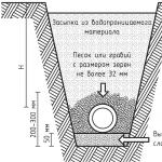
| Scheme of the main minimum dimensions of drainage ditches for various soil conditions |
|---|
 |
| The ratio of slope values in degrees, percentages and steepness of slopes (ratios of height to base length). On a semi-circular scale, this slanted line indicates the slope in degrees, and on a vertical scale, in percent. |
 |
|
Strengthening drainage or drainage ditches |
| Ways to strengthen the bottom and slopes of drainage ditches |
 |
Now consider how you can strengthen the slopes of the drainage ditch and at the same time decorate it with the help of perennials. A drainage ditch was surveyed in the village of Lemi in Finland.
 |
 |
|
| Nearly every Russian drainage ditch is like this: unformed and loose slopes and overgrowth of wild grasses. | However, near a house where the owner respects both himself and the people passing by, a drainage or drainage ditch may look completely different. A ditch can be made beautiful too! | |
 |
 |
|
| Stone paving is one of the ways to strengthen the slopes of the drainage ditch and give it an aesthetic appearance. | On loose and non-cohesive soils with large slope angles, it is required to strengthen the slopes of drainage ditches. A geogrid comes to help in strengthening the soil of the slopes of the ditch. The geogrid on the slopes is fixed with steel or plastic crutches, covered with a drainage layer of sand and fertile soil in which the seeds of wild (lawn) grasses are planted. | |
 |
 |
|
| Drainage ditch is a long excavation in the ground near the road. To break the monotony of the dominant length of a drainage ditch, a skilled landscaper creates rhythm by breaking up the ditch into sections with different textures and colors. Even the green fence covers only part of the site, so as not to create an unnecessarily gloomy atmosphere inside. By the way, this green hedge is made of solidago - an unpretentious perennial from the prairies of North America. | The green dominants of the slopes of the drainage ditch are made of perennial bergenia and Alba variegata hosta. | |
 |
 |
|
| Another dominant feature of the formation of the drainage ditch is the narrow-leaved cattail, better known among the people under the incorrect name "reed". Cattail dilutes the flatness and roundness of plantings on the slopes of the drainage ditch with swift vertical leaves. | The background for planting spots along the slopes of the drainage ditch will be a ground cover: for example, tenacious. | |
