When the developer of any device is faced with the question “How to get the right voltage?”, The answer is usually simple - a linear stabilizer. Their undoubted advantage is the low cost and minimal strapping. But besides these advantages, they have a drawback - strong heating. A lot of precious energy, linear stabilizers turn into heat. Therefore, the use of such stabilizers in battery-powered devices is not desirable. More economical are DC-DC converters. About them that will be discussed.
Back view:

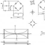
Everything has already been said about the principles of work before me, so I will not dwell on this. Let me just say that such converters are Step-UP (increasing) and Step-Down (lowering). Of course, I'm interested in the latter. You can see what happened in the picture above. The converter circuits were carefully redrawn by me from the datasheet :-) Let's start with the Step-Down converter:

As you can see, nothing tricky. Resistors R3 and R2 form a divider from which the voltage is removed and fed to the feedback leg of the microcircuit MC34063. Accordingly, by changing the values of these resistors, you can change the voltage at the output of the converter. Resistor R1 serves to protect the microcircuit from failure in the event of a short circuit. If you solder a jumper instead of it, then the protection will be disabled and the circuit may emit a magic smoke on which all electronics work. :-) The greater the resistance of this resistor, the less current the converter can give. With its resistance of 0.3 ohms, the current will not exceed half an ampere. By the way, all these resistors can be calculated by mine. I took the throttle ready, but no one forbids winding it myself. The main thing is that he was on the right current. The diode is also any Schottky and also for the desired current. In extreme cases, you can parallelize two low-power diodes. Capacitor voltages are not shown in the diagram, they must be selected based on the input and output voltage. It is better to take with a double margin.
The step-UP converter has minor differences in its circuit:

Detail requirements are the same as for Step-Down. As for the quality of the resulting voltage at the output, it is quite stable and the ripple, as they say, is small. (I can’t say about the ripples myself, since I don’t have an oscilloscope yet). Questions, suggestions in the comments.
Some time ago, I already published a review where I showed how to make a PWM stabilizer using KREN5. Then I mentioned one of the most common and probably the cheapest DC-DC converter controllers. Chip MC34063.
Today I will try to supplement the previous review.
In general, this chip can be considered obsolete, but nevertheless it enjoys well-deserved popularity. Mainly because of the low price. I still sometimes use them in my all sorts of crafts.
That's why I decided to buy myself a hundred of these mikruh. They cost me $ 4, now they cost $ 3.7 per hundred from the same seller, which is only 3.7 cents apiece.
You can find it cheaper, but I ordered them as a kit for other parts (reviews of a charger for a lithium battery and a current stabilizer for a flashlight). There is also a fourth component, which I ordered in the same place, but about it another time.
Well, I probably already tired with a long introduction, so I'll move on to the review.
I will warn you right away, there will be a lot of all sorts of photos.
It all came in bags, wrapped in bubble wrap. Such a bunch :) 
The microcircuits themselves are neatly packed in a bag with a latch, a piece of paper with the name is pasted on it. Written by hand, but I think there will be no problem recognizing the inscription. 
These microcircuits are produced by different manufacturers and are also labeled differently.
MC34063
KA34063
UCC34063
Etc.
As you can see, only the first letters change, the numbers remain unchanged, therefore it is usually called simply 34063.
I got the first ones, MC34063. 
Photo next to the same mikruha, but from a different manufacturer.
The monitored one is distinguished by a clearer marking. 
I don’t know what else to review, so I’ll move on to the second part of the review, the cognitive one.
DC-DC converters are used in many places, now it is probably hard to find an electronic device where they are not.
There are three main conversion schemes, all of them are described in 34063, as well as in its application, and in another.
All the circuits described do not have galvanic isolation. Also, if you look closely at all three circuits, you will notice that they are very similar and differ in the rearrangement of the three components, the inductor, the diode and the power switch.
The most common first.
Step-down or buck PWM converter.
It is used where it is necessary to lower the voltage, and to do this with maximum efficiency.
The input voltage is always greater than the output, usually at least 2-3 Volts, the greater the difference, the better (within reasonable limits).
In this case, the current at the input is less than at the output.
Such circuitry is often used on motherboards, although the converters there are usually multi-phase and with synchronous rectification, but the essence remains the same, Step-Down.
In this circuit, the inductor accumulates energy when the key is open, and after the key is closed, the voltage across the inductor (due to self-induction) charges the output capacitor 
The next scheme is used a little less often than the first.
It can often be found in Power-bank, where a stabilized 5 Volts is obtained from a battery voltage of 3-4.2 Volts.
Using such a circuit, you can get more than 5 volts, but keep in mind that the greater the voltage difference, the harder it is for the converter to work.
There is also one not very pleasant feature of this solution, the output cannot be disabled “programmatically”. Those. the battery is always connected to the output via a diode. Also, in the event of a short circuit, the current will be limited only by the internal resistance of the load and the battery.
To protect against this, either fuses or an additional power key are used.
Just like last time, when the power switch is open, energy is first accumulated in the inductor, after closing the key, the current in the inductor changes its polarity and, summing up with the battery voltage, goes to the output through the diode.
The output voltage of such a circuit cannot be lower than the input voltage minus the diode drop.
The current at the input is greater than at the output (sometimes significantly). 
The third scheme is used quite rarely, but it would be wrong not to consider it.
This circuit has a reverse polarity voltage at the output than at the input.
It's called an inverting converter.
In principle, this circuit can both increase and decrease the voltage relative to the input, but due to the nature of the circuitry, it is often used only for voltages greater than or equal to the input.
The advantage of this circuitry is the ability to turn off the output voltage by closing the power switch. The first scheme can do the same.
As in the previous schemes, the energy is stored in the inductor, and after the power switch is closed, it enters the load through the reversed diode. 
When I conceived this review, I did not know what to choose as an example.
There were options to make a step-down converter for PoE or a step-up converter to power the LED, but somehow it was all uninteresting and completely boring.
But a few days ago a friend called and asked me to help him solve a problem.
It was necessary to obtain a stabilized output voltage, regardless of whether the input is greater or less than the output.
Those. I needed a buck-boost converter.
The topology of these converters is called (Single-ended primary-inductor converter).
A couple more good documents on this topology. , .
The circuit of this type of converters is noticeably more complicated and contains an additional capacitor and inductor. 
This is how I decided to do it
For example, I decided to make a converter capable of producing stabilized 12 volts with input fluctuations from 9 to 16 volts. True, the power of the converter is small, since the built-in key of the microcircuit is used, but the solution is quite efficient.
If you power up the circuit, put an additional field-effect transistor, chokes for a higher current, etc. then such a scheme can help solve the problem of powering a 3.5-inch hard drive in a car.
Also, such converters can help solve the problem of obtaining, which has already become popular, a voltage of 3.3 Volts from a single lithium battery in the range of 3-4.2 Volts.
But first, let's turn the conditional scheme into a principal one. 
After that, we will turn it into a trace, but we will not sculpt everything on the circuit board. 
Well, next I will skip the steps described in one of mine, where I showed how to make a printed circuit board.
As a result, a small scarf was obtained, the dimensions of the board are 28x22.5, the thickness after sealing the parts is 8mm. 
Dug around the house all sorts of different details.
Chokes I had in one of the reviews.
Resistors are always there.
Capacitors were partially, and partially dropped out from different devices.
I soldered the 10uF ceramic from an old hard drive (they are also found on monitor boards), I took the aluminum SMD from an old CD-ROM. 
I soldered the scarf, it turned out kind of neat. I should have taken a photo on some kind of matchbox, but I forgot. The dimensions of the board are approximately 2.5 times smaller than a matchbox. 
The board is closer, I tried to arrange the board more densely, there is not very much free space.
A 0.25 Ohm resistor is formed by four 1 Ohm in parallel in 2 floors. 
There are a lot of photos, so I put it under the spoiler
I checked it in four ranges, but it accidentally turned out in five, did not resist this, but simply took one more photo.
I did not have a 13KΩ resistor, I had to solder it to 12, so the output voltage is somewhat underestimated.
But since I made the board just to check the microcircuit (that is, this board itself does not carry any value for me anymore) and write a review, I did not bother.
The load was an incandescent lamp, the load current was about 225mA
Input 9 volts, output 11.45 
At the input 11 volts, at the output 11.44. 
13 volts at the input, the same 11.44 at the output 
At the input 15 volts, at the output again 11.44. :) 
After that, I thought about finishing, but since the circuit indicated a range of up to 16 Volts, I decided to check it at 16.
At the entrance 16.28, at the exit 11.44 
Since I got hold of a digital oscilloscope, I decided to take oscillograms.
I also hid them under the spoiler, since there are quite a lot of them
This is of course a toy, the power of the converter is funny, although useful.
But to a friend, I picked up a few more on Aliexpress.
Perhaps someone will be useful. 
To power portable electronic equipment at home, mains power sources are often used. But this is not always convenient, since there is not always a free electrical outlet at the place of use. And if you need to have several different power sources?
One of the right decisions is to make a universal power supply. And as an external power source, use, in particular, the USB port of a personal computer. It's no secret that the standard one provides power for external electronic devices with a voltage of 5V and a load current of not more than 500 mA.
But, unfortunately, for the normal operation of most portable electronic equipment, 9 or 12V is required. A specialized microcircuit will help to solve the problem voltage converter on MC34063, which will greatly facilitate the manufacture with the required parameters.
Structural diagram of the mc34063 converter:

MC34063 Operating Limits


Description of the converter circuit
Below is a schematic diagram of a power supply option that allows you to get 9V or 12V from a 5V USB port on your computer.
 The circuit is based on a specialized microcircuit MC34063 (its Russian counterpart K1156EU5). The MC34063 voltage converter is an electronic control circuit for a DC/DC converter.
It has a temperature compensated voltage reference (RTF), a variable duty cycle oscillator, a comparator, a current limiting circuit, an output stage, and a high current switch. This chip is specially made for use in boost, buck and invert electronic converters with the smallest number of elements.
The output voltage obtained as a result of operation is set by two resistors R2 and R3. The choice is made on the basis that at the input of the comparator (pin 5) there should be a voltage equal to 1.25 V. You can calculate the resistance of the resistors for the circuit using a simple formula:
Uout= 1.25(1+R3/R2)
Knowing the required output voltage and the resistance of the resistor R3, it is quite easy to determine the resistance of the resistor R2.
Since the output voltage is determined, you can greatly improve the circuit by including a switch in the circuit that allows you to receive all kinds of values as needed. Below is a variant of the MC34063 converter for two output voltages (9 and 12 V) 
Published on 16.09.2011
I needed to get 5V from a higher voltage (and subsequently 3.3V). At the same time, it was necessary to ensure efficiency, since the battery was the power source and its charge is not infinite. There will also be no opportunity to organize a heat sink, the circuit will be sealed. Linear voltage regulators such as LM7805 and others like them will not help here. You need a pulse converter (DC-DC Converter), i.e. step-down voltage converter. The advantages of a pulse converter are obvious - high efficiency, does not require a heat sink (at least, if they get heated, then not as much as linear converters).
There are many specialized circuits, for example LM2574, LM2594, LM267x, LT1073, L4971, ST1S03, AS1333, ST1S03, ST1S06, ST1S09, ST1S10, ST1S12 (ST1Sxx- a very worthy series). They exist in different packages for different output voltages and currents. The cost of such chips is about 3 euros, but I need a reliable and inexpensive solution. Chip MC34063- this is what we need now. MC34063 very common, you can buy without problems. The cost is only from 0.2 euros! Works with voltage from 3 to 40 volts, maximum current 1.5A, conversion frequency 100KHz. By the way, on its basis it is possible to assemble a boost converter (see also “”), but now we will deal with a step-down converter.
The scheme is taken from the documentation. I did not have a 0.33 ohm limiting resistor (Rsc), I removed it at my own peril and risk. Schottky diode put the one that was. The values of the input and output capacitors are also different. For the first test option, it will do, but it's better not to save on this. This is how the scarf came out:

The photo shows a pulse buck converter with an output voltage of 3.3 V. The resistor values are R1=5.1KΩ, R2=10KΩ.
According to documentation MC34063 the maximum switching current is 1.5A. I didn’t have to load more than 0.2A, so I can’t tell you the “practical ceiling”.
But with such a load at an input voltage of 12V, all elements of the circuit remain cold.
Here you can use the form for calculating the circuit parameters: http://www.nomad.ee/micros/mc34063a/index.shtml
See also:
Very often the question arises of how to obtain the voltage required for the power circuit, having a source with a voltage different from the required voltage. Such tasks are divided into two: when: it is necessary to reduce or increase the voltage to the specified one. This article will consider the first option.
As a rule, a linear stabilizer can be used, but it will have large power losses, because. it will convert the difference in voltage into heat. This is where pulse converters come to the rescue. Your attention is invited to a simple and compact converter on the MC34063.
This chip is very versatile, it can implement step-down, step-up and inverting converters with a maximum internal current of up to 1.5A. But in the article only a buck converter is considered, the rest will be discussed later.
The dimensions of the resulting converter are 21x17x11 mm. Such dimensions turned out due to the use of both output and SMD parts. The converter contains only 9 parts.
The parts in the circuit are rated for 5V with a current limit of 500mA, with a ripple of 43kHz and 3mV. The input voltage can be from 7 to 40 volts.
The resistor divider for R2 and R3 is responsible for the output voltage, if they are replaced with a tuning resistor somewhere around 10 kOhm, then it will be possible to set the required output voltage. Resistor R1 is responsible for limiting the current. Capacitor C1 and coil L1 are responsible for the ripple frequency, capacitor C3 is responsible for the ripple level. The diode can be replaced with 1N5818 or 1N5820. To calculate the parameters of the circuit, there is a special calculator - http://www.nomad.ee/micros/mc34063a/index.shtml, where you only need to set the required parameters, it can also calculate the circuits and parameters of converters of two types not considered.
2 printed circuit boards were made: on the left - with a voltage divider on a voltage divider, made on two resistors of size 0805, on the right - with a variable resistor 3329H-682 6.8 kOhm. MC34063 microcircuit in a DIP package, under it are two tantalum capacitors of size D. Capacitor C1 is size 0805, output diode, current limiting resistor R1 is half a watt, at low currents, less than 400 mA, you can put a lower power resistor. Inductance CW68 22uH, 960mA.


Ripple waveforms, Rlimit = 0.3 ohm
These waveforms show ripples: on the left - without load, on the right - with a cell phone load, a 0.3 ohm limiting resistor, below with the same load, but a 0.2 ohm limiting resistor.

Ripple waveform, R limit = 0.2 ohm
Taken characteristics (not all parameters measured), at an input voltage of 8.2 V.
This adapter was made to charge a cell phone and power digital circuits on the go.
The article showed a board with a variable resistor as a voltage divider, I will place the corresponding circuit to it, the difference from the first circuit is only in the divider.


