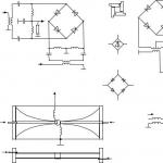
The crystal filter is known to be “half a good transceiver”. The proposed article presents the practical design of a twelve-crystal quartz filter of the main selection for a high-quality transceiver and set-top box for a computer, allowing you to configure this and any other narrow-band filters. Recently, in amateur designs, quartz eight-crystal ladder-type filters made on the same resonators are used as the main selection filter. These filters are relatively easy to manufacture and do not require large material costs.
Computer programs have been written for their calculation and simulation. The characteristics of the filters fully meet the requirements for high-quality signal reception and transmission. However, with all the advantages, these filters also have a significant drawback - some asymmetry in the frequency response (flat low-frequency slope) and, accordingly, a low squareness factor.
The workload of the amateur radio determines rather stringent requirements for the selectivity of a modern transceiver in the adjacent channel, so the main selection filter must provide attenuation outside the passband of at least 100 dB with a squareness factor of 1.5 ... 1.8 (at levels of -6 / -90 dB ).
Naturally, the losses and uneven frequency response in the passband of the filter should be minimal. Guided by the recommendations set out in, a ten-crystal ladder filter with a Chebyshev characteristic was chosen as the basis with a frequency response unevenness of 0.28 dB.
To increase the steepness of the slopes, additional circuits were introduced parallel to the input and output of the filter, consisting of series-connected quartz resonators and capacitors.
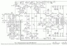
The calculations of the parameters of the resonators and the filter were carried out according to the method described in. For a filter bandwidth of 2.65 kHz, the initial values were obtained C1,2 = 82.2 pF, Lkv = 0.0185 H, Rn = 224 Ohm. The filter circuit and the calculated values of the capacitor ratings are shown in fig. 1.
The design uses quartz resonators for television PAL decoders at a frequency of 8.867 MHz, manufactured by VNIISIMS (Alexandrov, Vladimir Region). The stable repeatability of crystal parameters, their small dimensions and low cost played their role in the choice.
The selection of the frequency of quartz resonators for ZQ2-ZQ11 was carried out with an accuracy of ±50 Hz. The measurements were carried out using a self-made self-oscillator and an industrial frequency meter. Resonators ZQ1 and ZQ12 for parallel circuits are selected from other batches of crystals with frequencies respectively below and above the fundamental frequency of the filter by about 1 kHz.

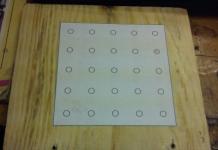
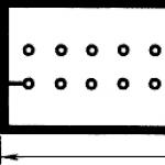
The filter is assembled on a printed circuit board made of double-sided foil fiberglass 1 mm thick (Fig. 2).
The top layer of metallization is used as a common wire. The holes on the side of the resonator installation are countersunk. The cases of all quartz resonators are connected to a common wire by soldering.
Before parts are installed, the filter PCB is soldered into a tin-plated box with two removable covers. Also, on the side of the printed conductors, a screen-partition is soldered, passing between the leads of the resonators along the central axial line of the board.

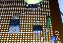
On fig. 3 shows the wiring diagram of the filter. All capacitors in the filter are KD and KM.
After the filter was made, the question arose: how to measure its frequency response with maximum resolution at home?
A home computer was used with subsequent verification of the measurement results by plotting the frequency response of the filter by points using a selective microvoltmeter. I, as a designer of amateur radio equipment, was very interested in the idea proposed by DG2XK, to use a computer program of a low-frequency (20 Hz ... 22 kHz) spectrum analyzer to measure the frequency response of narrow-band amateur radio filters.
Its essence lies in the fact that the high-frequency spectrum of the frequency response of a quartz filter is transferred to the low-frequency range using a conventional SSB detector, and a computer with an installed spectrum analyzer program makes it possible to view the frequency response of this filter on the display.
As a source of high-frequency signal DG2XK, a noise generator based on a zener diode was used. My experiments have shown that such a signal source allows you to view the frequency response up to a level of no more than -40 dB, which is clearly not enough for a high-quality filter setting. In order to view the filter frequency response at -100 dB, the oscillator must have
the side noise level is below the specified value, and the detector has good linearity with a maximum dynamic range of no worse than 90 ... 100 dB.
For this reason, the noise generator was replaced by a conventional sweep generator (Fig. 4). The circuit of a quartz oscillator is taken as a basis, in which the relative power spectral density of the noise is -165 dB / Hz. This means that the noise power of the generator at a detuning of 10 kHz in a bandwidth of 3 kHz
less than the power of the main oscillation of the generator by 135 dB!The source code has been slightly modified. So instead of bipolar transistors, field-effect transistors are used, and a circuit consisting of an inductor L1 and varicaps VD2-VD5 is connected in series with a quartz resonator ZQ1. The oscillator frequency is tuned relative to the quartz frequency within 5 kHz, which is quite enough to measure the frequency response of a narrow-band filter.
The quartz resonator in the generator is similar to the filter one. In the oscillating frequency generator mode, the control voltage to the VD2-VD5 varicaps is supplied from a sawtooth voltage generator made on a unijunction transistor VT2 with a current generator on VT1.
For manual tuning of the generator frequency, a multi-turn resistor R11 is used. Chip DA1 works as a voltage amplifier. The originally conceived sinusoidal control voltage had to be abandoned due to the uneven speed of the passage of the MCF in different sections of the frequency response of the filter, and in order to achieve maximum resolution, the generator frequency was reduced to 0.3 Hz. Switch SA1 selects the frequency of the "saw" generator - 10 or 0.3 Hz. The frequency deviation of the GKCH is set by a tuning resistor R10.

The schematic diagram of the detector block is shown in fig. 5. The signal from the output of the quartz filter is applied to the X2 input if the L1C1C2 circuit is used as a filter load.
If measurements are carried out on filters loaded with active resistance, this circuit is not needed. Then the signal from the load resistor is applied to the X1 input, and the conductor connecting the X1 input to the circuit is removed on the detector printed circuit board.
A source follower with a dynamic range of more than 90 dB on a powerful field-effect transistor VT1 matches the load resistance of the filter and the input impedance of the mixer. The detector is made according to the scheme of a passive balanced mixer based on field-effect transistors VT2, VT3 and has a dynamic range of more than 93 dB.
The combined gates of the transistors through the P-circuits C17L2C20 and C19L3C21 receive anti-phase sinusoidal voltages with a level of 3 ... 4V (rms) from the reference generator. The reference oscillator of the detector, made on the DD1 chip, has a quartz resonator with a frequency of 8.862 MHz.
The low-frequency signal formed at the output of the mixer is amplified by about 20 times by an amplifier on the DA1 chip. Since the sound cards of personal computers have a relatively low-impedance input, a powerful K157UD1 op amp is installed in the detector. The amplifier frequency response has been adjusted so that below 1 kHz and above 20 kHz there is a gain rolloff of approximately -6 dB per octave.

The oscillator is mounted on a printed circuit board made of double-sided foil fiberglass (Fig. 6). The top layer of the board serves as a common wire, the holes for the leads of the parts that do not have contact with it are countersunk.
The board is soldered in a 40 mm high box with two removable covers. The box is made of tin plate. Inductors L1, L2, L3 are wound on standard frames with a diameter of 6.5 mm with trimmers made of carbonyl iron and placed in screens. L1 contains 40 turns of PEV-2 0.21 wire, L3 and L2 - 27 and 2+4 turns of PELSHO-0.31 wire, respectively.
Coil L2 is wound on top of L3 closer to the "cold" end. All chokes are standard - DM 0.1 68 μH. Fixed resistors MLT, tuning R6, R8 and R10 type SPZ-38. Multi-turn resistor - PPML. Permanent capacitors - KM, KLS, KT, oxide - K50-35, K53-1.
The establishment of the GKCH begins with setting the maximum signal at the output of the sawtooth voltage generator. By controlling the signal at pin 6 of the DA1 microcircuit with an oscilloscope, the trimming resistors R8 (gain) and R6 (bias) set the amplitude and shape of the signal shown on the diagram at point A. By selecting the resistor R12, stable generation is achieved without entering the signal limiting mode.
By selecting the capacitance of the capacitor C14 and adjusting the L2L3 circuit, the output oscillatory system is tuned to resonance, which guarantees a good load capacity of the generator. The L1 coil trimmer sets the oscillator tuning limits within 8.8586-8.8686 MHz, which marginally covers the frequency response band of the tested quartz filter. To ensure maximum restructuring of the GKCh
(not less than 10 kHz) around the connection point L1, VD4, VD5 the top layer of foil is removed. Without load, the output sinusoidal voltage of the generator is 1V (rms).
The detector unit is made on a printed circuit board made of double-sided foil fiberglass (Fig. 7).
The top layer of foil is used as the common wire. Holes for the conclusions of parts that do not have contact with a common wire are countersinked.
The board is soldered in a tin box 35 mm high with removable covers. Its resolution depends on the quality of manufacture of the attachment.
Coils L1 -L4 contain 32 turns of wire PEV-0.21, wound round to round on frames with a diameter of 6 mm. Trimmers in coils from armor cores SB-12a. All chokes type DM-0.1. Inductance L5 - 16 μH, L6, L8 - 68 μH, L7 - 40 μH. Transformer T1 is wound on an annular ferrite magnetic circuit 1000NN of size K10 x 6 x 3 mm and contains 7 turns in the primary winding, 2 x 13 turns of PEV-0.31 wire in the secondary.
All tuning resistors - SPZ-38. During the pre-tuning of the block, a high-frequency oscilloscope controls the sinusoidal signal at the gates of transistors VT2, VT3 and, if necessary, adjusts the coils L2, L3. Trimmer coil L4 the frequency of the reference oscillator is removed below the filter bandwidth by 5 kHz. This is done in order to reduce the number of various interferences that reduce the resolution of the device in the working area of the spectrum analyzer.

The swept frequency generator is connected to a quartz filter through a matching oscillatory circuit with a capacitive divider (Fig. 8).
During tuning, this will allow you to get low attenuation and ripple in the passband of the filter.
The second matching oscillatory circuit, as already mentioned, is located in the detector attachment. Having assembled the measurement circuit and connected the output of the set-top box (X3 connector) to the microphone or line input of the sound card of a personal computer, we launch the spectrum analyzer program. There are several such programs. The author used the program SpectraLab v.4.32.16, located at: http://cityradio.narod.ru/utilities.html. The program is easy to use and has great features.
So, we launch the “SpektroLab” program and, by adjusting the frequencies of the GKCh (in manual control mode) and the reference oscillator in the detector attachment, we set the peak of the GKCh spectrogram to around 5 kHz. Further, by balancing the mixer of the detector attachment, the peak of the second harmonic is reduced to the noise level. After that, the GKCh mode is turned on and the long-awaited frequency response of the filter under test appears on the monitor. First, the swing frequency of 10 Hz is turned on and, by adjusting the center frequency using R11, and then the swing band R10 (Fig. 4), we set an acceptable “picture” of the filter's frequency response in real time. During the measurements, by adjusting the matching circuits, a minimum non-uniformity in the passband is achieved.

Further, to achieve the maximum resolution of the device, we turn on the swing frequency of 0.3 Hz and set the maximum possible number of Fourier transform points (FFT, the author has 4096 ... 8192) and the minimum value of the averaging parameter (Averaging, the author has 1) in the program.
Since the characteristic is drawn in several passes of the GKCh, the storage peak voltmeter mode (Hold) is switched on. As a result, on the monitor we get the frequency response of the filter under study.
Using the mouse cursor, we obtain the necessary digital values of the obtained frequency response at the required levels. In this case, one must not forget to measure the frequency of the reference oscillator in the detector attachment, in order to then obtain the true values of the frequencies of the frequency response points.
After evaluating the initial “picture”, the frequencies of the series resonance ZQ1n ZQ12 are adjusted, respectively, to the lower and upper slopes of the filter's frequency response, achieving a maximum squareness of -90 dB.
In conclusion, using the printer, we get a full-fledged “document” for the manufactured filter. As an example, in fig. 9 shows the spectrogram of the frequency response of this filter. The spectrogram of the GKCH signal is also shown there. The visible unevenness of the left slope of the frequency response at the level of -3 ... -5 dB is eliminated by rearranging the ZQ2-ZQ11 quartz resonators.

As a result, we obtain the following filter characteristics: bandwidth by level - 6 dB - 2.586 kHz, frequency response unevenness in the passband - less than 2 dB, squareness factor by levels - 6/-60 dB - 1.41; by levels - 6/-80 dB 1.59 and by levels - 6/-90 dB - 1.67; attenuation in the band - less than 3 dB, and behind the band - more than 90 dB.
The author decided to check the results obtained and measured the frequency response of the quartz filter point by point. For measurements, a selective microvoltmeter with a good attenuator was required, which was a microvoltmeter of the HMV-4 type (Poland) with a nominal sensitivity of 0.5 μV (at the same time, it captures signals well with a level of 0.05 μV) and an attenuator of 100 dB.
For this measurement option, the scheme shown in Fig. 1 was assembled. 10. Matching circuits at the input and output of the filter are carefully shielded. Shielded connecting wires are of good quality. The “earth” chains are also carefully made.

By smoothly changing the frequency of the GKCH with resistor R11 and switching the attenuator by 10 dB, we take the readings of the microvoltmeter, passing through the entire frequency response of the filter. Using the measurement data and the same scale, we build a graph of the frequency response (Fig. 11).
Due to the high sensitivity of the microvoltmeter and the low side noise of the GKCH, signals at the level of -120 dB are well fixed, which is clearly reflected in the graph.
The results of the measurements were as follows: bandwidth level - 6 dB - 2.64 kHz; uneven frequency response - less than 2 dB; -6/-60 dB squareness ratio is 1.386; by levels - 6 / -80 dB - 1.56; by levels - 6/-90 dB - 1.682; by levels - 6/-100 dB - 1.864; attenuation in the band - less than 3 dB, behind the band - more than 100 dB.
Some differences between the measurement results and the computer version are explained by the presence of accumulating digital-to-analogue conversion errors when the analyzed signal changes in a large dynamic range.
It should be noted that the above graphs of the frequency response of the quartz filter were obtained with a minimum amount of tuning work and with a more careful selection of components, the filter characteristics can be noticeably improved.
The proposed oscillator circuit can be successfully used for the operation of AGC and detectors. By applying the signal of the oscillator to the detector, at the output of the set-top box to the PC we get the signal of the low-frequency oscillator of the oscillating frequency, with which you can easily and quickly adjust any filter and cascade of the low-frequency path of the transceiver.
It is no less interesting to use the proposed detector attachment as part of the panoramic indicator of the transceiver. To do this, connect a quartz filter with a bandwidth of 8...10 kHz to the output of the first mixer. Further, the received signal is amplified and applied to the input of the detector. In this case, you can observe the signals of your correspondents with levels from 5 to 9 points with good resolution.
G. Bragin (RZ4HK)
Literature:
1. Usov V. SSB quartz filter. - Radio amateur, 1992, No. 6, p. 39, 40.
2. Drozdov VV Amateur KB transceivers. - M.: Radio and communication, 1988.
3. Klaus Raban (DG2XK) Optimizierung von Eigenbau-Quarzfiltern mit der PC-Soundkarte. - Funkamateur, No. 11, 2001, S. 1246-1249.
4 Frank Silva Shmutzeffekte vermeiden und beseitig. - FUNK, 1999, 11, S. 38.
Fig.1 Quartz filters with "parallel" capacitances
Arrows AA and BB show the second option for switching on KPI. Resistors R1, R4 (0 ... 300 Ohm) are installed in the presence of large emissions in the frequency response. Capacitor C4 * is selected in the range from 0 to 30 pF.
In order to minimize the number of capacitors, filter circuits containing only parallel capacitances were chosen, Fig.1. Since the filters are symmetrical (with respect to their input-output), it turned out to be possible to use dual KPIs from broadcast receivers with a capacitance of 12 - 495 pF. In addition, you will need one more, pre-calibrated in pF, single-section variable capacitor.
The filter setup is as follows.
For tuning, you may need a device for measuring the amplitude-frequency characteristics X1-38 or similar. I use an oscilloscope and a homemade prefix (see below).
Initially, all capacitors are set to a position corresponding to a capacitance of 30 ... 50 pF. By controlling the frequency response of the filter on the screen of the device, by rotating the capacitors within small limits, we achieve the required bandwidth. Then, by adjusting the variable resistors (use only non-inductive ones, for example, SP4-1) at the input and output of the filter, we try to equalize the top of the frequency response. The above operations are repeated several times until the desired frequency response is obtained.
Further, instead of each individual section of the KPI, we solder a pre-calibrated capacitor, with which we try to optimize the frequency response of the filter. On its scale, we determine the capacitance of a constant capacitor and make a replacement. Thus, all sections of the KPI, in turn, are replaced by capacitors of constant capacitance. We do the same with variable resistors, which we will later replace with constant ones.
The final "finishing" of the filter is made directly in place, for example, in the transceiver. After installing the filter in the transceiver, it may be necessary to correct the values of these resistors, while for optimal matching of the filter with the mixer output and the input of the IF, the GKCH and the oscilloscope must be connected according to the diagram shown in Fig. 2.

Fig.2 Connecting a quartz filter for final adjustment
Several filters were made according to the described method. I would like to note the following. Setting up three or four crystal filters with some skill takes no more than an hour, but with 8 crystal filters the time is much higher. At the same time, attempts to pre-configure first two separate 4-crystal filters, and then dock them - turned out to be fruitless. The slightest scatter of their parameters (and this always takes place) leads to distortion of the resulting frequency response. It is also interesting to note that theoretically equal capacitances (for example, С1=СЗ, in Fig. 1a; С1=С7; СЗ=С5, in Fig. 1b) after tuning with a graduated KPI according to the optimal frequency response, had a noticeable spread.
In my opinion, the advantage of this technique is its visibility. On the screen of the device, you can clearly see how the frequency response of the filter changes depending on the change in the capacitance of each capacitor. For example, it turned out that in some cases it is quite enough to change the capacitance of one capacitor (with the help of a relay) in order to change the filter bandwidth without much deterioration in its squareness.
As noted above, an S1-77 oscilloscope and a converted attachment for measuring the frequency response are used to set up the filter.
Why C1-77? The fact is that on its side wall there is a connector on which there is a sawtooth voltage of the sweep generator. This allows you to simplify the attachment itself and exclude the sawtooth voltage generator (SPG) from its circuit. Therefore, there is no need for additional synchronization and it becomes possible to observe a stable frequency response at various sweep times. Obviously, other types of oscilloscopes can be adapted, maybe with a little refinement.
Since the simplified prefix is used only when working with quartz filters near the frequency of 8 MHz, all other subbands were excluded from it.
Also, in the used set-top box, you will need to slightly increase the output voltage. To do this, it is enough to convert the output stage into a resonant one. It must be tuned to resonance every time a new filter is connected to its output.

Fig.3 Attachment to the oscilloscope for setting up quartz filters
Literature.
- V.Zalneruskas. A series of articles "Quartz filters" Magazine "Radio" No. 1, 2, 6 1982, No. 5, 7 1983
- S. Bunin, L. Yailenko "Handbook of the shortwave", ed. "Technique" 1984
- V. Drozdov "Shortwave transceivers" ed. "Radio and Communications" 1988
- Magazine "Radio" No. 5 1993 "Sweeping frequency generator"
You often come across the phrase in articles: “A quartz filter is easier to set up using curve tracers (for example, X1-38, X-1-48, SK-4-59, etc.). Of course, if they are, then the filter setting is simple. But this if you have the appropriate device, and even the instructions for it.Otherwise, the word "simple" will quickly turn into its opposite "difficult".Therefore, this article focuses on setting up a quartz filter using the simplest devices.
Some articles omit information about the type of filter to be adjusted (ladder, bridge, monolithic), describing general tuning rules. However, I came to the conclusion that each of them has, along with common ones, also its own characteristics.
Let's start by setting up the ladder type filter (Fig. 1).

Fig.1
Experience shows that:
The filter is obtained with the best parameters if all quartzes have as close as possible the series resonance frequencies (±10 Hz). However, do not be upset if this condition is not feasible, because a good filter is obtained even with a frequency spacing of up to 1 kHz;
It is best to select quartzes by including them in the reference oscillator of the device in which this filter is supposed to be used, and use the lowest frequency of them directly in the reference oscillator. In this case, the tuning elements of the generator should not be touched;
The filter should be configured directly in the "native" device;
If quartzes have different frequencies, they should be arranged in the following sequence: set the highest frequency first at the input, and all subsequent ones - in turn from left to right, in rank, with decreasing frequency;
Capacities should be used small-sized, with a minimum temperature coefficient of capacity (TKE) with an accuracy of no worse than ± 1.5%. But do not despair if there are none, because in the process of setting them up you still have to pick them up. In most cases, during the tuning process, up to 90% of the containers are replaced with other (albeit close) denominations;
It is better to use filter quartz (taken, for example, from disassembled factory filters).
So, from four filters for a frequency of 10.7 MHz (type FP2P-325-10700M-15), you can assemble four eight-crystal ladder filters (these filters have four pairs of quartz with the same frequencies) with different, but close to 10.7 MHz frequencies. Usually, several radio amateurs do this (usually 4 people) with one filter each. The most experienced of them selects four sets of quartz of the same frequency, then quartz with a minimum. keeps the scatter for himself, and gives the rest back to his friends (or vice versa?!). With somewhat less success, generator quartz can also be used.
At home, a quartz filter can be adjusted in three ways.
In the first case, you should use (except for the tuned device) as an auxiliary device another transceiver with a digital scale, in the second case - GSS (standard signal generator) and a frequency meter (with a limiting frequency exceeding at least the lowest frequency of your tuned device, for example 1.9 MHz). The frequency meter measures either the frequency of the GSS or the frequency of the GPA of the apparatus under study.
In the third case, a quartz local oscillator is used for one of the operating frequencies (either a GSS or another transceiver without a digital scale), and a digital scale is required in the device being tuned.
In all three cases, an RF signal of the operating range is fed to the input of the tuned device. In the first two cases, the supplied frequency is slowly changed in the transparency band of the quartz filter, while taking the readings of the S-meter in relative units, and every 200 Hz they are recorded in a table. Then, according to the table, graphs (frequency response) are built. The S-meter readings are plotted vertically, and the frequency is plotted horizontally. By connecting the points marked on the graph with an interpolation (averaging) line, the frequency response is obtained - the amplitude-frequency characteristic of the newly made filter.
In the third case, everything is done in the same way, only the tuned device itself is tuned in frequency, taking readings directly from its digital scale and S-meter at the same time.
In this case, the "newly made" filter, as a rule, has:
A different lane than required;
Unevenness in the upper part of the frequency response;
Gentle (and sometimes with emissions) lower slope of the frequency response.
In the future, the filter is adjusted in the three above directions in order of priority.
At the first stage of tuning (coarse tuning), you should obtain a filter bandwidth of up to 2.4 kHz by alternately replacing the capacitances, starting from the filter input, and then taking the frequency response. In doing so, keep in mind the following:
If additional capacitances are installed parallel to quartz (especially extreme ones) and their value is increased (up to a certain limit), then the filter bandwidth will decrease. A similar effect will be observed with an increase in the capacitances of the capacitors going to the case. With a decrease in the values of these capacitances, the opposite effect will be observed. This property is used to narrow the bandwidth of the crystal filter in CW mode. Thus, the bandwidth can be reduced to 0.8 kHz. With further narrowing of the band, the attenuation of the filter in the transparency band sharply increases (to obtain low attenuation in the CW filter, one should use resonators with a Q factor at least an order of magnitude greater than the Q factor of the filter);
The magnitude of "humps" and dips in the upper part of the frequency response (linearity of the characteristic) will depend not only on the value of the selected capacitances, but also on the resistance value of the load resistors installed at the input and output of the filter. With a decrease in their resistance, the linearity of the characteristic improves, but the attenuation in the passband of the filter increases;
If it is not possible to obtain sufficient steepness of the lower slope, quartz should be installed in parallel with the load resistors, similar to those used in the filter, while from all available quartz, the lowest frequency should be selected or its frequency should be lowered by connecting the inductor in series. By selecting the number of turns of this inductance, you can change the steepness of the lower slope;
The filter setting must be repeated several times. If at the last stage of tuning it is not possible to obtain an acceptable frequency response, it is necessary to try to adjust the frequency of the series resonance of individual quartz. To do this, a capacitor is installed in series with the quartz, and by selecting this capacitor, generation is achieved at the frequency of the remaining quartz. If this does not help (and this may be with a small separation between the frequencies of the parallel and series resonances of the quartz), the quartz should be replaced. Quartz in the filter should be placed in a chain, carefully shielding the input from the output. Figure 2 shows the frequency response of the KF receiver "TURBO-TEST", taken at different values of the capacitances of the capacitors. -

Fig.2- For greater clarity, the frequency values were taken without observing the received sideband and the actual IF value. Figure 3 shows the frequency response of the final filter setting. -

Fig.3
Now some practical tips for setting up a bridged crystal filter. Such a filter is shown in Figure 4. Coils L1 and L2 contain 2x10 turns of wire with a diameter of 0.31 mm; ferrite rings from the FP2A-325-10.700 M-15 filter are used as cores. The filter bandwidth is 2.6 kHz.
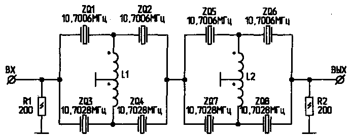
Fig.4
If you have a low-pass filter (2...6 MHz), it usually turns out to be narrower than required, and if a high-pass filter (8...10 MHz) is too wide-band. In the first case, it is necessary to expand the bandwidth by connecting to the upper or lower (Fig. 4) quartz inductors, which should be selected experimentally. In the second case, in order to reduce the bandwidth, it is necessary to connect trimmer capacitors in parallel with the resonators (similar to coils). The quartz in the filter must be selected with an accuracy of 50 Hz (series resonance frequency), and the frequencies of all upper resonators must be the same and differ from the lower ones (also the same) by 2 ... 3 kHz.
If only quartzes of the same frequency are available, you can change the frequency of the quartzes by erasing the silver layer from the crystal (increase the frequency) or by shading with a pencil (decrease). But practice shows that the stability of the parameters of such a filter over time leaves much to be desired.
More stable results are obtained by adjusting the frequency by connecting a tuning capacitor in series with quartz. After tuning, it is advisable to replace the capacitor with a constant capacitance of the same value.
With a large filter bandwidth, a dip (attenuation) may appear in the middle of its frequency response. It should be said that its depth largely depends on the resistance of the resistors R1 and R2. Their value can be from hundreds of ohms (with a bandwidth of 3 kHz) at frequencies of 8 ... 10 MHz to several kilo-ohms at lower frequencies and with a smaller filter bandwidth. In the manufacture of a bridge filter, great attention should be paid to the symmetry of its shoulders, as well as the windings of the transformers included in it, and, of course, careful screening of the input from the output. For more information about bridge filters, see.
Literature
1. Goncharenko I. Ladder filters on unequal resonators. - Radio, 1992, No. 1, S. 18.
2. Bunin S.G., Yaylenko L.P. Handbook of a radio amateur-shortwave. - K .: Technique, 1984, S. 21 ... 25.
Purification of water with homemade filters is a standard event for camping and field conditions. After all, it is unreasonable to carry huge bottles on yourself because of the incredible physical costs. In addition, it is irrational because of the almost ubiquitous presence of the liquid component of the earth's shell necessary for the body.
The liquid required by people is indeed everywhere, but its sanitary condition is not always compatible with consumption. But you can make a very effective water filter with your own hands even on a multi-day route, being far from settlements, with a minimum of improvised means.
We will introduce you to the most effective and easy-to-implement devices for purifying dirty water. Here you will find diagrams, recommendations and a detailed description of the manufacturing technology. The material offered for review is systematized, supplemented with visual illustrations and video instructions.


How to choose a filter media?
When choosing a container for a filter, you need to calculate everything properly, because the cleaning properties primarily depend on a properly formed “filling”. The volume of the filter container must be such that it can easily accommodate all components.
As an absorbent, natural materials are widely used, such as quartz river or washed quarry sand, gravel, activated carbon and zeolite. As you know, any filter begins with a primary coarse layer. Often this role is assigned to fabric materials based on cotton.

The water in the filter must go through several stages of purification. The upper layers trap large inclusions and impurities, the lower ones exclude the penetration of small particles
Natural materials are highly impractical in terms of hygiene. Firstly, in a humid environment, such a filter layer is subject to decay processes, which causes an unpleasant odor. Secondly, the structure of the fabric implies a very rapid contamination of the filter with unwanted particles, which increases the need to change the layer.
Much better performance is observed in synthetic counterparts. More preferable in this regard is lutrasil. The material has moisture-resistant qualities and is more resistant to contamination than cotton or bandage.

Non-woven polypropylene fabric - lutrasil can be used as the bottom layer for final water treatment
A very budget option for a fabric filter can be considered a synthetic layer that is used in making coffee.
Quartz sand does an excellent job of retaining small particles, as well as filtering heavy chemical compounds. While gravel is the opposite, it is better to weed out large inclusions of unwanted materials. A mineral called zeolite has an incommensurable cleansing effect.

Zeolite is widely used in the field of water purification. Extracts from it heavy metals, organic compounds, phenol, nitrates, ammonium nitrogen, etc.
The active effect of the substance with a bang will cope with water pollution with metal and salt suspension, and also neutralize pesticides and other products of processing of the agricultural industry.
Activated carbon cleaners
The most common group of homemade filters involves the use of activated carbon. The drug can be purchased at any pharmacy in unlimited quantities. Its reserves will practically not increase the weight of the luggage and will not take up much space in the backpack.
But in terms of the strength of the cleansing action, coal has few rivals. It perfectly adsorbs toxic substances, absorbs an impressive range of heavy metals, and mercilessly fights against harmful microorganisms.
Small-sized varieties of marching type
Perhaps the most high-quality filtration result is shown by home-made options based on activated carbon. The absorbent will equally successfully cope with the delay of both mineral formations and toxic substances.
Image Gallery


The properties of the material include the ability to impart transparency to the liquid, as well as eliminate unpleasant odors and waste products of microorganisms.
When choosing coal, you need to pay attention to the structure of the mineral. Too small, powdery - will penetrate into the water, and large, on the contrary, will not provide the proper level of purification. (It is worth giving preference to granular starting material).

Activated carbon is the most popular material in homemade filter devices. It is advisable to fill it in layers so that there is a powdery material below, granules on top, and the fractional composition increases in height.
An important factor is the degree of so-called "roasting" of coal. If you overdo it with this procedure, the absorbent will quickly lose all its valuable qualities.
Charcoal can be bought at any supermarket or made at home. The best absorbent qualities are observed in hardwoods, in particular birch.
To get coal, you need to load wood into any metal container and heat it up on fire (preferably put in a furnace). After the wood is red hot, remove the container and let it cool - that's it, the charcoal is ready for use in the filtration system.
Image Gallery


A completely camping option would be a home-made carbon-based water filter for water from the ashes of a burned-out fire. On occasion, it is better to use whole pieces of about 4 cm in length.
As a rule, anything can serve as a case for such an impromptu system, but mostly a plastic container or bottle is used for convenience.
Making a carbon water purifier
Before assembling, you need to choose a more optimal version of the case.
For this you will need:
- Several plastic containers (bottles or PVC pipe, food containers can be used in some cases. Because of their strength, they will serve well as the basis of the cartridge).
- Tools for plastic processing (various sharp objects: awl, scissors, clerical knife, screwdriver).
- Absorbent material (in this case, activated carbon).
- Additional filter granules (quartz sand, gravel).
- Material for the primary fabric filter (medical bandage, gauze or coffee filter).
- Plastic caps or plugs.
For the tightness of the structure, polymeric substances should be used at the joints of the modules (if the filter is multi-level and consists of several parts). Moisture resistant silicone glue or insulating tape works well.
To mount the suspended structure, you need to first cut the bottom from the plastic bottle with a clerical knife. Then make two holes opposite each other for fastening the loops. Now the improvised body can be hung, for example, on a tree branch.
Next, you need to make an outlet valve, from where the filtered liquid will flow. At this stage, the design feature depends on individual preferences. You can organize something according to the principle of a shower - make many small holes in the lid, or you can drill one big one.
The next step will be the actual laying of the components. Having twisted the perforated cover, the body is turned over or hung by the hinges. Then, first of all, a bandage folded several times, or gauze, is laid. The use of a coffee filter is also encouraged.
In some cases, you can find designs where the role of the primary filter material is performed by a fabric cover sewn specifically for the size of the housing. This greatly simplifies the task of changing the absorbent and saves time.
It is worth paying attention to the fact that the laying of absorbent components should be carried out according to the “pyramid” type. This means that the first step is always fine-grained absorbent (coal), then comes a layer of quartz sand, and then comes the turn of river pebbles or gravel.

Each subsequent layer of the filter has a different, often finer structure than the previous one. This contributes to a more thorough cleaning.
For greater efficiency, it is recommended to alternate several layers of pebbles, however, do not forget that excess material may interfere with the flow of water. It is better to cover the filler hole with some kind of cloth or lid in order to avoid getting unwanted objects inside the cartridge.
The principle of operation of such a filter is the passive flow of water through all layers. Under the action of the granules, the contaminated liquid is cleared and flows out of the perforated hole. Initially, several liters of water must be passed through the filter. The first filtering procedure will wash the layers and remove contaminants.
The disadvantages of the system include a rather slow cleaning speed and the need to constantly fill in new liquid after the filtration procedure is completed.

The disadvantages of homemade water filters with natural fillers include low speed, the need to frequently change filter layers, and not very high quality cleaning.
Useful homemade PVC pipe
To purify water in a suburban area, you can also make an effective purifier that can compete with. It will be required to process water drawn into or into, but it will be especially useful if water is drawn from a river, pond or lake.
For the construction of the structure, you will need a piece from a plastic water pipe and 2 containers. You can connect two bottles, where the upper segment will act as a coarse filter.

The filter can be made from improvised means without the help of special equipment. Everything you need can be found in everyone's home
Inside, as expected, the primary layer of gauze or cotton wool is first placed, while constructing a kind of mesh substrate, for example, made of plastic, so that the layers do not mix. A plastic cover is well suited for this, which can be glued into a PVC pipe, then drill several holes of small diameter around the circumference.

Perforation in the plastic baffle is necessary to retain the synthetic or natural fibers of the primary filter
After that, close the module with a lid again, only this time you should not resort to using glue, because this part must be removable in order to be able to replace and clean the filter material.

It is worth laying the filler tightly, but at the same time not too much so that the layer does not interfere with the passage of water
Then the turn of the plastic pipe begins. From the bottle you need to cut off the neck and fix it inside the pipe so that it is possible to use the thread.
It should be fixed tightly to avoid leaks (silicone glue works well). It is recommended to wrap the outer side and the edge of the neck with several layers of electrical tape for greater strength.

It is necessary to wind the insulation in several layers also in order to prevent the possibility of leakage.
At the other end of the tube, as usual, you need to insert a cap and make a perforation. A fabric layer should be placed on the inner surface of the impromptu cassette.
After all the manipulations, the structure is ready for filling with granulate (in this case, activated carbon). For better efficiency, you can alternate layers of minerals inside the pipe.

It is best to use synthetic material as a filter layer, because. it is more durable and does not need to be replaced frequently
When completed, the primary filter and the charcoal module are threaded together. Then plastic bottles are added on both sides. That's it, the cut PVC carbon filter is ready to use.

Homemade design does not require special conditions of use and does not take up much space when disassembled
Aquarium water filter
As you know, for the normal life of aquatic inhabitants, it is necessary to clean the tank in a timely manner and maintain the purity of the water. Owners of small aquariums will come in handy with instructions for building a filter at home.
The body of a homemade hard water filter can be any plastic tube of a suitable diameter, including, in the absence of such, 2 syringes will work well.
Before assembly, you need to prepare some additional parts: a spray bottle (often used in detergent bottles), a sponge with a high degree of rigidity, as well as a mechanism by which the structure will be attached to the wall of the aquarium (suction cup).

The main advantage of the design is ease of manufacture. All components can be easily found at home
The first step is to remove the movable part of the syringe, it will not come in handy. Then, using hot glue or other sealant, connect the workpieces to each other, after cutting off the spouts.
For the flow of water, it is necessary to make a perforation. An ordinary soldering iron will do just fine with this, and if you don’t have one, you can heat any metal object, such as a nail, over the fire and make holes over the entire area of \u200b\u200bthe syringe.

To optimize the speed of water passing through the filter, it is recommended to make holes at a uniform distance from each other.
In some cases, it is possible to fill the filter capsule with some kind of granulate, the best option would be to use zeolite, because. The absorbent does a good job of filtering out nitrates. Next, you need to place the atomizer inside the case, while its flexible tube should go evenly along the entire length of the cassette.
Then the makeshift cartridge should be completely wrapped with a sponge and the outer layer fixed so that it does not unwind. That's all, the power of such a filter is quite enough to purify the water in a small aquarium.

The design is quite compact and can fit in any small tank
Sand option for the pool
As already mentioned, the process of building small-sized variations of filter systems is quite simple, however, if we are talking about a large reservoir, it is necessary to think through all the nuances of the purification system.
Many probably faced the problem of "blooming" of water. Most often, this process is observed in the warm season, and if it is also equipped with a heating system, such an opportunity can occur at any time.
It is fair to say that the problem of green water can be completely solved by improvised means, namely, removed mechanically, but sometimes a layer of algae can sink to the very bottom and removing the surface film will not solve the problem.
In order for the water to circulate through the filter, an inexpensive vortex pump is included in the circuit. Install it after the filter

Before turning on the pump, the filter must be closed with a lid so that conditions for normal suction are formed inside it.


In addition, not only algae can act as a pollutant, but also fallen leaves, as well as sand and all kinds of microparticles if the pool is outdoors.
Faced with problems of this kind, people begin to feverishly buy all sorts of detergents and cleaning products, hoping to get rid of annoying green islands. But the active chemical action of substances can only help with the pollutant that is on the surface, and in order to clean the tank to the very bottom, completely different methods are needed.
For a complete cleaning of the pool, there are special ones. They work on the principle of a "vacuum cleaner", namely, they pump liters of contaminated liquid through the compressor. The filtration process is a reusable distillation of water from one part of the pool to another.
This mechanism is often used in large municipal or private institutions, where the volume of the pool sometimes reaches thousands of liters, so the best solution is an automated filtration system.
But it is not profitable for the average user to invest in such bulky equipment if, for example, only a small seasonal inflatable tank needs to be cleaned.
Just for such reservoirs there is an instruction for the construction of a sand filter.

The body of the device contains a filler with filtering properties (sand). You can replace the material with any other
During the assembly process, you will need any container that can perform the functions of a cartridge. The water tunnel from the primary filter can be made from a plastic pipe 2 meters long (in case the pool is large).
You also need to take into account that the design of the tunnel involves a 90-degree turn, so you need a PVC corner. The size of the inner diameter of the cartridge and pipe should be about 50 mm.
A threaded bush with an M10 diameter can be used as a support pin for the cleaning modules. The convenience of this design allows you to connect several filter cassettes into one, which turns an ordinary filter into a multi-level one. This increases the efficiency of absorption and, as a result, the water becomes cleaner.
At the first stage, you need to make two holes (it is better to use a puncher).
The first is in the filter plug, and the second is in the PVC corner, then connect the two parts with a pin and nut. At the other end of the tube, a water compressor should be fixed. The power of the equipment should be selected based on the volume of the pool.
In order for the filter to be floating, it is necessary to make a special foam substrate.
The purification process is circular, and occurs by means of taking water from the lower layers of the pool and pumping it through the filter using a pump.
The advantage of this design is the absence of additional elements for the release of filtered water, as well as the possibility of replacing the cartridge. The rinsing procedure is best done over a separate container to avoid getting dirty liquid back into the pool. It is better to use a bucket for this.
In addition, the cost of this installation is much less than branded counterparts. Everything you need can be purchased at specialized outlets, for example, a compressor is sold at any pet store, PVC pipes and corners in building supermarkets, and a replacement cartridge in the markets in the plumbing department.
A big plus when creating a floating filtration system is the freedom of design thought. If you have decorative components at hand, you can disguise the filter as any object that fits into the composition of the pool, for example, a ship.
Homemade water filter
At home, everyone is able to build an installation consisting of three containers connected in series. Such a water filter works only under a certain pressure of the plumbing system.
As future cassettes, you can use plastic or glass containers, and you need to connect the segments using a ¼ inch adapter nipple.

The filter is connected directly to the water supply system and does not require installation of additional communications
For convenience, the adapters are provided with inlet/outlet guides. They will make sure that the build process is successful. Another important point is the tightness of the installation. To avoid leaks, it is recommended to wrap each thread in Teflon tape, and seal the joints with synthetic material.
A filter of this type is connected to the system as a tee and connected in series with the water supply pipes. As a granulate, you can use the same coal. It will purify raw water from harmful microparticles and prevent the appearance of scale on the heating elements of the electric kettle and washing machine.
Conclusions and useful video on the topic
After some time, you will have to replace the home-made system with a more professional one. This is due not only to the wear of old parts, but because of their low absorbent and cleaning efficiency in relation to microorganisms contained in water.
To ensure the sterility of the reservoir, modern filters are equipped with a mineralizing system. Before buying equipment, it is worth testing the water in the laboratory for mineral content and then, based on the results of the examination, select a filter with the appropriate mineral composition.
There is no such function in homemade equipment, therefore, after the cleaning stage, it is recommended to boil the filtrate. Also compare the power of the filter with the pressure of the water. Incorrect calculation of the intensity of water pressure in relation to a home-made filtration system can affect the performance of the equipment.
Video #1 The process of making a simple filter from a plastic bottle:
Video #2 For those who want to make a miniature version of the water filter, this video will help:
Video #3 Construction of a filter for a private reservoir:
There really is no limit to the ingenuity of people, and this is clearly confirmed by the variations of the filters presented. A wide choice of materials, fillers and an abundance of shapes are suitable for any occasion when you need to quickly purify water.
