“For 8 years I played Spectrum in black and white and everyone knows why, but because our valiant RGB TV sets did not understand the signal at all.” I would like to say, to stumble, to remember that the sun used to be brighter and the grass greener. But I won’t say, in my childhood no one ever said the word Spectrum. All my childhood I played dandy, later sega, with friends sometimes in supernintendo. Neither in Dendy's New Reality program, nor in Ot Screw, nor in any magazine have I heard about this computer. I've heard vaguely about computers that boot from cassette tapes, but I've never seen them or know their names. I first learned about it only when I got the Internet. I read the forums, envied those people who in the late 80s and early 90s assembled their own computers, but I missed the fit. Although in those years I was small and, with all my desire, I would not have assembled my clone of the Spectrum. How much have I lost? This is a question I started asking myself not too long ago. A year ago, I came across a very good video where one guy told in great detail and showed how to solder a Leningrad Spectrum clone. I reviewed it more than once and in the end decided “I will assemble my computer from scratch!”.
I decided to take the original scheme of Leningrad from sblive.narod.ru as a basis. Well, add a bunch of improvements, such as correcting the drawing of a circle (it is not clear how Zonov could design a computer with such a fierce jamb. It is expressed in font problems, jambs of graphics, etc.), stabilization of the crystal oscillator, stabilization of frame and horizontal synchronization, refinement of the INT signal, introduction of binding to black level.
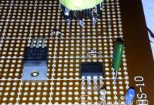
To make this process even cooler and more interesting, I did not look for a ready-made board, I ordered a breadboard of rather compact dimensions 12 * 18. I also had to order chips and other small things from aliexpress and CHIPiDIP. The memory and processor had to be soldered from a non-working clone, which I recently received from a spektrumist. I still don’t know what kind of clone it is, there is no circuit for it, and I just soldered the microchips out of it.
I decided to put all the microcircuits on panels for quick replacement if something goes wrong. But after all, the Spectrum contains a ROM, and it still needs to be flashed, I didn’t have a programmer, but the world is not without good people. Instead of two EPROMs, I decided to put one EEPROM W27C512, into which I sewed 48k BASIC, 128K BASIC, TR-DOS and a memory test for 48k, it's also nice to be able to switch memory banks with jumpers. But now all my details came, having thought in advance where which socket would stand, I began to solder them. Well, I stuck stickers on the board with inscriptions where which microcircuit and the numbers of the legs, which greatly facilitated my life in the future.
Devoting a couple of hours a day for two and a half weeks, I still collected it. Couldn't wait to plug it in. And after turning it on, I saw a white screen, what a good idea I thought. After rechecking the entire board, removing a couple of jambs, the situation did not improve. For a long time I could not understand what was the matter, but then I found out that you should not interfere with CMOS and TTL microcircuits. Yes, I'm still a radio amateur. I had to order parts again and wait. After replacing all CMOS chips with TTL, the coveted inscription still appeared, but the image floated.
An appeal to the zx-pk.ru forum made it somewhat clear what was happening, but I did not have a solution. As a result, I had to sit for hours over the scheme. And voila, I just misunderstood the scheme for finalizing the formation of the INT signal, or rather, at first I understood it correctly, and then I thought that it was wrong and did it with a jamb. Well, another problem has been fixed. But not everything is as rosy as we would like, frames were constantly running on my multimedia monitor. And then I decided to connect with the good old SHARP TV, which never let me down. But the truth is in b/w, since there is no RGB scart in it. And the picture on it almost did not twitch. Again, an appeal to the forum gave good advice, to make a filter for a switching power supply.
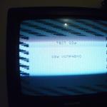
And finally, the picture is normal, no twitches, we run a memory test.

But the Spectrum also needs a keyboard. Then I got out in a rather original way, took the old keyboard, pulled out a film with contacts from it, cut the getinaks into pieces, soldered the contacts on it, processed them with a file and glued them with hot glue to the clave, and soldered them according to the scheme. It turned out to be a rather bulky external clave. Well, I built the ports for Sinclair joysticks directly into the keyboard. Joysticks from Sega Master Systems or Atari are suitable, well, or, as in my case, a Sega joystick soldered inside, for which I brought the spacebar (namely, it is almost always used as an additional one) to button A, well, when you press button C, pressing up is duplicated, which is convenient in platformers.
It didn’t work out for me with the speaker and I just brought the beeper to the TV, so at least the volume can be adjusted. Having written a simple melody in BASIC, having tested the sound, I decided to download some kind of game. And ... nothing happened to me. I assembled a tape reader on the K554CA3, tried several microcircuits, double-checked the entire circuit, but it didn’t start, why, it’s still not clear. I rebuilt the reader on 561LN2 according to the scheme from the Pentagon-48 (first on a breadboard before soldering) and everything worked the first time. Although games were loaded, most of them hung immediately, some, like DIZZY 5, managed to play a little.

Once, when I woke up in the morning, I wondered if I soldered the capacitors correctly ... and OMG, instead of 47 nanofarads, I soldered 47 picofarads, and I also wanted something to work. Once again we order the missing parts, we are waiting. After the global soldering of the capacitors, you can finally play normally, nothing else hangs. I had to reassure myself that most of the games on the Spectrum are monochrome anyway, and I don’t lose much, that in the late 80s, not everyone had color TVs and many played it with a b/w picture. But somehow it didn’t help much, you know.

And on my LCD monitor, the frames were still running. In the end, I still decided to solder an additional microcircuit to shorten the horizontal sync pulse, which I wanted to install at the beginning of the assembly, but for some reason I decided to save money. As a result, I finally got a good color picture.

The image is a little double. Checked on the LCD TV, doubling is not visible. The picture is great. Super! But there is still free space on my board and it would be foolish not to use it. It would be great to expand the memory to 128k and play the 2015 castlevania. To do this, we will change our K565RU5 to K565RU7 or an analogue of MN41256-08, which can be bought on aliexpress without any problems. Having added 7 more microcircuits, including the YM2149F sound chip, the board was completely filled. There were no problems with the memory upgrade. I expanded the memory to 256k according to this scheme, but still I use it in 128k mode.
In the end this is what happened


Initially, I didn’t intend to use the board on the table and for this I picked up a case from an old TV set-top box, theoretically you can put an additional drive controller board on the second floor there, but I don’t want to bother with it yet.


Speccy games turned out to be fierce hardcore, I only managed to get through the recently released Mighty Final Fight.

So how much did I lose by not having that computer as a kid? In terms of games, it's unlikely, although the ability to transfer games from cassette to cassette could really appeal to me. In terms of programming in BASIC, it would hardly have interested me at that time.
DESCRIPTION OF THE COMPUTER DIAGRAM
Х.Х The device and operation of the computer
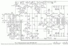
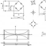
Schematic diagram of the computer is given in APPENDIX 4
(Insert at the end of the book).
♦ CLOCK GENERATOR.
Assembled on elements D1 and D2. Frequency is set by quartz
resonator at 14 MHz, and at outputs 5 and 6 of the counting trigger
D2.1, two anti-phase series are produced half as small
frequencies. If you have quartz at a frequency of 7 MHz, then, set
By setting the SA1 jumpers to the appropriate position, you can
exclude the counting trigger on element D2.1 from the circuit and use
use antiphase signals from outputs 6 and 8 of the element
D1, following with the frequency of quartz.
♦ UNIT FOR SYNCHRONIZATION AND FORMATION OF A TV FRAME.
Signals of synchronization and formation of television
frame, as well as the management of RAM regeneration, are formed appa-
multiple of the signals at the outputs of counters D3-D6. At the exit
Counter D3 generates NO, HI, H2 and NC signals. Invert-
ruyu signal BUT, we get the signal CAS for clocking the micros-
hem RAM. RAS signal switching address multiplexers
D15, D16, is obtained by delaying the signal BUT for one cycle (you-
move 9 of element D2). The inverted RAS signal serves to
processor clock. The "SCREEN" signal is a sign of the on-screen
area - is used to load shift registers D33, D41.
The signal "BORDER" - a sign of a border - loads into registers
gated multiplexers D30, 1)31 color attributes bor-
dera.
The signals at the outputs D3-D6 and triggers of the D8 chip serve
to determine position numbers in a line and line numbers in
frame. At the output of element 3 D44, a lowercase
sync pulse SS. At the output 6 of the D40 element,
vertical sync pulse KS with a frequency of 50 Hz. With the same hour
This element D1 (output 10) generates an interrupt signal
IHT, on which during the reverse beam of the TV
polling kj> khviatura and other input devices.
It is not necessary to use quartz with a frequency of 14 in a computer
(or 7) MHz. The synchronization scheme allows setting for an hour -
Totu of the generator is quite wide. For this purpose
designed jumpers SA2, which can change the coefficient
D4 counter recalculation point. Enable preset inputs
counter D4 depending on the frequency of quartz is shown in tab.
face on the computer diagram (see APPENDIX 4 (insert)). At
generator frequency, a multiple of 500 kHz, it is possible to obtain
standard vertical sync frequency (50 Hz). If
the frequency of your quartz is not a multiple of 500 kHz, then you need to set
jumpers to the position corresponding to the nearest specified in
frequency table. TV timing stability is not
will suffer. Naturally, with a change in the frequency of the generator,
Torah will change the speed of the computer, but it's not scary,
since when you enter from a magnetic tape, the computer is configured
on the frequency of the signals from the tape recorder.
♦ CENTRAL processor.
The basis of the computer is the Z80A processor - one of the most
powerful eight-bit processors, very popular for
abroad. Mass production of its domestic counterpart
1810VM80 - unfortunately, not yet established.
Registers D46, D47 perform the role of address bus forming
drivers, and the D51, D52 microcircuits form a bidirectional bus
data.
The functions of the system controller are performed by elements D14 (on
outputs 3 and 11 generate signals for accessing external
devices IORD - input, IOWR - output), D10 (outputs 10 and
13), D12 (at outputs 3 and 6, RDROM signals - reading ROM and
CSRAM - access to RAM).
♦ PERMANENT MEMORY.
Consists of two K573RF4 microcircuits and has a volume of 16K
byte. It contains a monitor, a BASIC interpreter and familiar
generator. In addition, there is a K573RF2 chip containing
a computer test program. Firmware codes TEST-
ROMs are given in APPENDIX 1.
♦ RANDOM MEMORY.
The 48K byte DRAM node includes
actually memory chips D21-D28 type 565RU5, multip-
lexors D15-D19 type 555KP11 and buffer register 555IR22
(D32). Here, the capacity of 565RU5 microcircuits is used not half-
accuracy, since the upper 16K bytes of the address space are
cessors are assigned to a permanent storage device. Multi-
typexers D15, D16 form addresses when accessed by the process
litter to RAM, and D17-D19 - addresses of regeneration and access to ei-
deooregions of RAM.
♦ VIDEO SIGNAL FORMING UNIT.
The video signal generation unit is assembled on shifting relays
hysters D33, D41 and D35, gated multiplexers D30,
D31, D36 multiplexer, D11 elements (outputs 3, 6, 11),
D13 (output 11), D43 (output 12) and transistors VT4-VT10.
To shift register D33 at the end of the data access cycle
images on the SCR signal, these data are entered in parallel
code, and then issued in sequential code with frequent
that TI. At the end of the cycle of accessing attribute data by task
him to the front of the H2 signal into the internal registers of the multiplex
ditch D30, D31 attributes are entered. Shift register D35 for-
keeps the image data signal for a period of time between downloads
shift register D33 and loading internal registers
multiplexers D30, D31. When the beam is outside the boundaries of the
defield multiplexer registers D30, D31 are loaded from
second inputs with data coming from the border register
(D39). Switching inputs of multiplexers D30, D31 control
Gives the signal "BORDER"
The final processing of the serial data code is
The deoimage is produced by element D11 (output 3). In the presence of
high level at output 12 of multiplexer D31 at input 1
element D11 pass "blink" pulses "FLASH" from the output
11 counter D7. The input 2 element D11 receives a sequence
real image data "VBYTE" from the output of the shifter
hyster D35. From the output 3 of the D11 element, the image data with
the "blink" attribute is fed to input 1 of the D36 chip, pack-
matching with a sample of the color of the dot or the color of the field. At the entrance 15 of this
the same microcircuit receives a mixture of lowercase and vertical sync
pulses from element D11-11 (if you use a TV type
UPIMTST) or from element D43-12 (for a ZUSST TV).
At the outputs 4, 7 and 9 of the D36 multiplexer, signals are generated
piles of flowers. At output 12 of this microcircuit,
signal designed to increase the brightness of color signals
cash that adds up with each color signal on
resistor-diode matrix (diodes VD5-VD7 and resistors R29-
R38). Then the chrominance video signals through emitter repeaters
tels on transistors VT4-VT6 are fed to the "TV" connector. These
the same signals are summed on a resistor matrix (R42-R44), to
it adds the signal "SYHC" (a mixture of vertical and lowercase
sync pulses) through resistors R32, R41, and this mixture
blunts to the emitter follower VT7, forming a "VIDEO" signal
for black and white TV. Moreover, each of the signals is color-
ness goes to the summation through resistors of different values
minala to turn a color image into black and white
halftone.
Transistors VT8-VT10 form inverted signals
R,G,B. Depending on the TV used, the selection is direct
of the switched or inverse signals R, G, B is carried out by jumpers
♦ OUTPUT PORT.
Made on the chip D39 (555TM9). His ranks are Q2-Q4
determine the color of the border, the Q1 bit with the
RC filter (R24, R26, C12, C13) generates an output signal to
tape recorder, discharge Q0 - sound signal. Data to register
are recorded by the processor, that is, the border color signals, you
water to the tape recorder and a sound signal are generated by the program
rammno.
♦ INPUT PORT.
Assembled on multiplexers D37, D38 type 555KP11 and working
melts as follows. Polling signals KA8-KA15 from addressable
processor buses through decoupling diodes VD11-VD18 and connector
■ "KEYBOARD" enter the keyboard and through a closed contact
pressed key passes to one of the inputs of the D37 microcircuits or
D38 (in the form of signals KL0-KL4), from where, in the presence of a signal
IORD and low on the address bus AO hits the bus
data. If the AO bit of the address bus is high,
then signals are read from the joystick (DV0-DV4) and tape recorder
(TIN signal).
♦ INPUT UNIT FROM TAPE RECORDER.
The input node consists of an operational amplifier A1
(K140UD1208), acting as a limiting amplifier, and
comparator A2 (554SAZ), which generates standard TTL levels
from the input signal.
X.2 Replacement of elements
♦ PROCESSOR.
Any Z80 or compatible processor can be used
him, for example U880 produced by the GDR. It is only necessary to take into account
that processors that do not have a letter index in the designation
(Z80) are designed for clock speeds up to 2.5 MHz, so do not
all their instances will operate at the frequency of the generator 14
MHz, although most will still work. In this case, wish
It is important to set the generator frequency close to the minimum.
Processors Z80A, Z80B can be installed without restrictions.
♦ ROM CHIPS.
Instead of K573RF4 microcircuits, you can use K573RF6 or their
foreign analogue - ROM type 2764. In this case, the switching circuit
Will not change. In extreme cases, instead of two K573RF4, you can
use eight microcircuits of the K573RF2 or K573RF5 type (for
boundary analogue - 2716), including them according to the scheme shown in
rice. 1.1. Here, the 555ID7 decoder selects the desired
ROM chips. Of course, they will have to be mounted on a separate
board, placing it next to the main board. At the same time,
The load on the address buses will increase and it is desirable that the buses
addresses have been buffered. The current consumption will also increase.

There is another way to reduce the number of deficient micro-
Roschem ROM. To do this, write in the K573RF2 chip or
K573RF5 codes from the table of APPENDIX 3, and set the ata mic-
roschemu in place of ROMO, having previously bent its output
21. Connect pin 21 to panel pin 28. Perform on
board changes shown in fig. 1.2. Bold lines you-
the newly introduced elements and connections are divided, and the crossed out
ties must be broken.
A resident bootloader will be written to the ROM.
After turning it on, it checks the RAM in addresses O -
16384, where the operating system will then be loaded.
After the test is completed, the screen displays:
Enter the program "MONITOR-16K" from the tape recorder (coincides
with the contents of ROMO-ROM1, input time is about 1.5 minutes), which
paradise will be loaded into addresses 0-16384 of RAM and there will be a price from dos-
dumb. Further work does not differ from working with standard
version of the ROM. You can work with all programs and
Rotate in the OS with the "RESET" button. After turning off the power,
it will be necessary to load "MONITOR-16K" again.
After these changes, you can use other versions
OS, for example, with a Russian font, etc.
♦ RAM CHIP.
You can safely use 565RU5 microcircuits with indices B,
C, D. Difficulties may arise with 565RU5D microcircuits
due to their low performance. But you can try to
beat the reliable operation of microcircuits 565RU5D, reducing the frequency
clock generator. Without changing the schema, you can set
565RU7, connecting their conclusions 1 to a common wire, but their capacitance
only a quarter will be used. Basically, it is possible
the use of microcircuits 565RU6, but they will need 32 pieces plus
additional decryption schemes similar to how it was
made when replacing 573RF4 with 573RF2. The design is obtained
cumbersome and complex, so the scheme of such refinement does not apply
found.
♦ MICROCIRCUIT* 555 SERIES AND OTHER ELEMENTS.
All 555 series microcircuits can be changed without restrictions to
similar chips of the 1533 series. Some may be
also replaced by 155 or 531 series chips.
replacement of registers, multiplexers, counters and other mics
roschems in the Zonov scheme for microcircuits of the 155 and 531 series are limited
cheny, mainly in that their inputs are connected to the outputs
memory or processor chips that have a low
load capacity. Can be replaced by series 531 and 155
multiplexers D17-D19 and D36, as well as counters D3-D6 and some
other logic chips that do not load the processor buses
and RAM.
As for the D30-D33 microcircuits (according to the Zonov scheme), then they,
in principle, can be replaced with 531 series microcircuits, but with
condition so that the outputs of the RAM chips are loaded no more than
than one or two inputs of the 531 series microcircuit, and the rest
the microcircuits connected to them were from the 555 or 1533 series.
the same can be said about the microcircuits that load the busbars
cessor.
Register D32 can be replaced by 555IR23 by inverting
WRBUF signal at input 11, as provided on the proposal
circuit (jumper SA6). By function
register 555IR22 is completely similar to register 580IR82, but
it, unfortunately, has a different pinout and more
Energy consumption. Register 555IR9 in the Zonov scheme can be replaced
thread for two registers 555IR16, including it as in our scheme
(D33, D41). In both schemes, the 555IR16 registers can be replaced
on 555IR1. You don't need to change the wiring diagram.
In our scheme, as address bus drivers, you can
apply any microcircuits intended for this
(580IR82, 555AP4, etc.) in the corresponding inclusion, and in some
as a bi-directional data bus buffer are ideal
microcircuits 555AP6, 580VA86. Counter 561IE10 can be replaced
on 555IE19 (the pinout is different!). Comparator 554S.AZ
him on 521SAZ, which differs in the type of case and the numbering of the output
dov. Operational amplifier 140UD1208 can be replaced with
140UD12 without changing the circuit, or on 140UD6 (140UD608), claim-
By turning on the resistor connected to pin 8. Transistors can be
install any of the KT315, 312, 342, 3102 series.
Good afternoon (optional evening/night).
I want to dedicate my 20th review to the computer that won my heart. I invite you to visit this lamp post. Be sure to mark all the former and current owners of these magnificent devices, share ideas, links, gadgets for our favorite computer. Please lean back in your chair and gradually sink. (The review is very large, contains instructions, diagrams, thoughts on assembling and upgrading)
FOREWORD
A long time ago, in a galaxy far, far away...
This man, whom you see from above, is not casual here. This is Clive Marles Sinclair himself, the former owner of Sinclair Radionics, which produced Spectrum computers. This is the same person who wanted to make the cheapest apparatus for work, period. Yes, he did not like games and believed that this was a waste of time and a wrong investment. (I wonder what he would say now, looking at the wildly developing gaming industry). Yes, let the experts correct me, this gentleman went into the invention of electronic bicycles with his head and it seems that he stayed there, making something like this:

Otherwise, it's a completely different story. Today we will talk about a set for self-assembly of a computer, a bygone era, the end of the 80s.
I first met the Spectrum when I was 7 years old, my father assembled it for me. Then I discovered a whole wonderful world of games and programming.
As one good man said - “If you once met the Spectrum, then it will deeply sink into your soul and one day, when it becomes completely unbearable, you will run around the flea markets and look for it.” And it is true. There is only one big BUT. You can buy, of course, on eBay there are lots selling both 48k and 128k models. But one day, when I was "unbearable" looking for information about the Spectrum, I came across this site, which offers ready-made kits for self-assembly of the device.
I was very surprised, people sell and make boards of the Soviet copy of Leningrad 48k with the corrected circuit. There are certainly pros and cons to this option. But guys, here they offer to assemble a computer with their own hands, but what could be cooler than understanding the principles of computer operation at the hardware levels ?! It's just a fairy tale. Naturally, for such work it is desirable to have experience, little, my experience in assembling computers is limited to the RK-86 model from the Radio magazine, compared to the Spectrum, it is a grain of sand, in terms of complexity, and you will have to work hard to debug it.
As usual warning:

All responsibility, namely independent penetration into the body of the finished product with subsequent violation of its integrity of performance, lies with the person who committed this action.
In addition to the above, when working with memory chips, use a grounded, anti-static wrist strap so as not to damage the integrity of the chip, just do not forget to connect Video, RGB, Scart and the like cables only to devices that are turned off.

PREPARING FOR ASSEMBLY
This kit is supplied without RAM, memory chips are used and at the moment it is difficult to find them, you can also use chips, but with minor modifications in the circuit.Where to get? We dismiss flea markets right away, analyzes also due to the fact that the chips can be damaged, among other things, there are features with this kind of memory, namely, it is sensitive to working in one batch (more precisely, all the chips installed in the machine should preferably be of the same batch, revisions and dates of production, as well as cities of production), I encountered this when assembling RK-86, Soviet memory is too capricious, it is even advisable to buy new chips in bulk, you never know what.
Therefore, having called all the stores in Yekaterinburg, the chips were found in only one - at a fabulously low price. It is understandable who in our time may need such a small RAM, and even so slow.
Especially before buying, I asked to bring a package of chips, so that I could make sure that they were pouring from this particular box. Maybe I was overly suspicious in this decision, but you never know what.

And the following resistor values:

On the little things, an audio jack for Jack - 3.5, additional sockets, if you do not want to solder the microcircuits. It is possible to install SMD cases of resistors, diodes, capacitors (for example, blocking capacitors can be replaced with SMD).
The tool will require the following set:
1. soldering station / soldering iron with temperature control,
2. oscilloscope (very, even very desirable),
3. multimeter,
4. if there is no oscilloscope, we use a logic analyzer.
SUPPLIED KIT
I often pay little attention to the packaging, because I'm used to deliveries from China, but Russian packaging is always worth a look, I'll put it under the spoiler, whoever wants to take a look, look.Package


Microcircuits and spare parts were wrapped in a bag and glued with adhesive tape:

The board itself is laid with two pieces of corrugated cardboard and wrapped in packaging polyethylene:

So, let's take a look at this beautiful set of spare parts.
Pay. You know, this board is made at the highest level, just incredibly well. I have not held such high-quality custom boards in my hands for a long time. Wiring, silk-screen printing and inscriptions ... Mmmm magnificence, let's just enjoy:


Some of the inscriptions on the board are breathtaking, I really like them.
I also attach photos in a large size of the board as a whole, in order to fully appreciate the quality of workmanship, it does not smell of handicraft:


The kit comes with cribs for RAM, ROM, CPU chips:

The crumble that comes with the board in the kit. (Beeper, a set of BC547 transistors, capacitors for all the necessary ratings, 2.54mm pin connectors, quartz at 14.000 MHz, diodes):

All logic that is required to run a computer (including CPU and ROM). By the way ROM - the memory is already flashed by Sinclair BASIC:

For orientation in the microcircuits of the times of the USSR, I drew the following picture:

Of all the microcircuits, not a single military commissar, two marked statics- K561LN2 and K561IE10A and a bunch of various enterprises.

ASSEMBLY
We use the two presented schemes and, if you ever want to figure it out more closely or run into difficulties, we begin to slowly collect. The most important thing is to keep track of exactly what and where we put.Also to help the layout of microcircuits and other elements:

The main thing in this matter is not to rush, otherwise you will get completely confused. I started the assembly with little things (capacitors, resistors, diodes). Complete capacitors (blocking, nominal value 104) I changed to my own - Murata Manufacturing. Plant quartz last, due to the fact that it is very close to the resistor R1 and if you solder quartz at the root, the resistor will have to be soldered by surface mounting.
How not to do it!
At first I decided to put everything on DIP sockets ( and it was a big mistake), I thought that if the microcircuit fails, then I can always easily buy it, but in practice everything turned out differently, I collected all the glitches. You can read about glitches and their solutions below.


Toward the end of the assembly, I began to assemble a tape reader module based on the K561LN2 microcircuit, the module diagram is classic, I attach below:


Test run with wired Video cable with CPU and RAM installed:

Strange, but it should be:

It looks like there is something there. Looking at the board, I found a couple of errors:
1. Resistor C2 is not soldered.
2. Resistor C1 is not installed correctly.
I also replaced the remaining capacitors (blocking), with a face value of 104, with Murata. Replaced transistor K315B.
Iiii nothing, after making all the replacements and then turning on the device, I got this:

At the same time, there is 5V in a circle, but the CPU does not start. Sadly. I started looking for the reason, along the way, ordering a logic analyzer.
1.5 months passed and there was no result, I already started to get upset, as a notification about the parcel came from the mail - the analyzer arrived.
The signal analyzer is a device based on chips that is a USB2.0 peripheral controller and an 8-channel receiver (I would even say sniffer) that captures from the data lines.


This device works using the software package -.
It seems that everything is there to solve the problem, but the problem remains the same as it was.
I suffered for a long time until I decided to take down all the cribs for microcircuits, leaving only RAM, CPU and ROM.
And lo and behold, everything worked! (But my RK-86 was assembled on the same panels, and everything works)
This is what the debug process looked like:


As a result, long and painfully rechecking everything and cutting off leg 1 from the DD4 chip (K555IE7) with the accompanying soldering to the ground, I got the image:

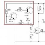
Face progress. Do not pay attention to the scan, the TV is old and has a problem in this area. Further, if you look closely, you will see that the icon - © is displayed incorrectly, this is the famous problem of the Leningrad 48K computer (incorrect drawing of circles), it is solved as follows, we cut off the track from IR9 -> 1 and LN1-> 10 and solder the following circuit:


In general, when using different logic manufacturers, you need to individually select the capacitors for the sweep from the DD4 -> IE7 and DD6 -> IE7 microcircuits, in fact, empirically, a capacitor is placed on the first and second between the ground and the 11th leg.
KEYBOARD MANUFACTURING
A computer is certainly good, but without the ability to enter, it makes no sense to have it, so we will make a keyboard!The keyboard pinout is in the main circuit for Leningrad 48K:

For the keyboard we need:
1. Textolite size 100x160.
(I decided to make a compact keyboard in order to fit the device into a compact case, and in general I like compact keyboards).
2. Laser printer for LUT.
3. The buttons are tactile, the height is selected independently.
Unpacking, marking and cutting:


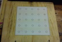
We prepare and cut out the template for the LUT:
Open the editor and draw the keyboard:

In the editor, it is drawn with a second layer, but let's just say, you don't need to poison this layer, save your time, you shouldn't poison for the sake of poisoning.
For you, I have prepared a ready-made template for printing:

Mirror pattern NO NEED!
Then we print it and cut it out:

For etching, you will need the following kit:
1. 100 ml pharmacy 3% hydrogen peroxide
2. 30 g citric acid
3. 5 g of table salt.
4. Capacity.
For a board of my size, this is enough with my head, and for the speed of etching, I prudently drew polygons, so that the solution would not be wasted.
We transfer it to the workpiece with an iron, I advise you to use the substrate from the oracle:

It can be seen that I corrected the small flaws with a marker resistant to ferric chloride and threw it into the solution:

At the end I got this result. I will say right away that I screwed up, in order for the inscriptions to be clearly visible, I kept it a little longer in the solution and spoiled the tracks in some places:

Well, okay, this is not criminal, we take a wire of 0.5 mm and solder the tracks:


READY FOR LAUNCH
Oh how good he is!
We're starting!

Install the PlayZX application on your phone or tablet:

Using the AUX cable, we cling to the Spectrum, turn on the device and go into download mode ( on the Spectrum keyboard, press J -> while holding SS, press P twice, you will see this entry - LOAD "" and press enter). After that, select the desired image of the game in the phone and click play. The game will be loading.

The program download process is as follows:

Downloaded Saboteur game file:

And of course, an example of loading a program from scratch, let's check the same saboteur:
CONCLUSIONS
And so let's summarize. Buying this computer, you are not just buying a stupid model for assembling similar to Chinese ones, you are gaining a large layer of experience in assembling such computers. As I said before, in my childhood I had a similar computer, although it was 128K and had 5.2-inch floppy disks, in any case I was pleased with the result.If not for this computer, I would not have acquired a new tool, such as a signal analyzer and a hot tin suction, for desoldering microcircuits and, of course, experience.
Nuances, the platform is completely copied from Leningrad 48K, it can be adjusted to different quartz depending on the complete, logical base, which is very good.
It works stably, using the PlayZX application, you will discover the world of games for the ZXSpectrum, and I myself was surprised by such a large library.
A very large community around the world, by the way, some people release new games for these computers, and also port old NES, for example, Castlevania.
PS. An excellent start in microelectronics for a child and a great pastime for solving a particular problem.
P.S.S. The review turned out to be simply gigantic, but there is so much to tell, but we will have to limit ourselves to the essence, in the next DIY we will make a case for this device and we will screw RGB and SCART, there are ideas to make it in the form of a laptop.
Information to help assemblers Leningrad 48K:
1.
2.
3.
Liked the review
+253
+425
11 / 11 829
print version
It just so happened that "Leningrad" was the very first Spectrum that I saw, and it was also my first computer in general. Despite its simplicity and underdevelopment, so many memories are associated with this computer that I can’t just forget about this Spectrum clone.
Leningrad was designed by Sergei Zonov in the late 80s. The boards show the date 1988 (ZS88):
Boards dated 1989 come across:
The computer is simple, contains a minimum number of chips. Decryption of ports for reading is utterly simplified - all even ports are considered a keyboard port (254), all odd ones are considered a Kempston joystick port (31). This disgrace comes from the fact that only one bit of the address bus, A0, is used to decrypt the ports. An even greater disgrace is created with output ports, in particular with the #FE port - it works when a value is written to any port at all, i.e. there is no decryption.
In addition to the "curve" of port decoding, the computer has a non-standard video output. This manifests itself when trying to connect it to TV tuners, PAL encoders and, in general, to modern LCD TVs. As a rule, such attempts end in nothing. This problem is solvable, I will talk about this a little later.
All the "Leningrads" I have seen are assembled in cases of the "coffin" form factor. Jokes aside, the shape of the case with beveled corners is somewhat reminiscent of a coffin. In terms of size, all cases are approximately the same, the difference is only in the material from which the case is made.
Let me illustrate with examples:

This is all that's left of my very first computer. The case (by the way, quite massive for such a small size) is quite well preserved, and I still hope to assemble a Spectrum in it.
There are also lighter aluminum cases:


This copy is well preserved and has been restored. Now it looks like new. Compared to the previous chassis, this complete computer weighs less than a steel chassis.
The third type of housing is plastic. From my point of view, the worst case:


Note the almost complete absence of blocking capacitors on the board. Despite this glaring shortcoming, the board worked remarkably well without failures for the previous owner for a good ten years.
If a toad was strangling a ready-made computer, then you could try to assemble the "Leningrad" yourself, since it was not so difficult. I also soldered one "Leningrad" on my own when I was in my first year at university. Then (in the mid-90s) it was possible to buy an empty Leningrad board on the radio market for ridiculous money without any problems:

Such boards differed in one feature - somewhere in the area of \u200b\u200bthe tape former they had a short circuit of the + 5V and GND power buses. If the corresponding jumper was not cut when assembling the computer, then when you first turned it on, there was a great chance to get puffs of smoke with the burnout of one or more printed tracks on the board in a random place. Fortunately, I knew about this feature, and I called in time and eliminated the place of the circuit.
There, on the market, computer circuits, microcircuits, keyboards, cases were sold. In short, then there was a real paradise for the assembly of such structures. By the way, about keyboards: buttons from calculators were mainly used:

The photo shows the old inscriptions on the keys with peeled stickers. These are clearly buttons from some kind of calculator. In terms of quality and reliability, such keyboards did not stand up to criticism. Maybe such lousy buttons are good for calculators, but they are not at all suitable for a computer. Especially for games. I remember I hesitated to bend the contacts in such buttons so that they would somehow work. Perhaps the only positive thing about these buttons is their cheapness and availability. Therefore, at the first opportunity, I switched to reed keys, which were much more convenient to work with:


It turns out that there were also such "Leningrads" - with a built-in keyboard and a system connector. The scheme of this "Leningrad" almost completely coincides with the canonical scheme. The exception is the tape input, beeper output and video output. Decryption of #FE port in this clone is corrected compared to the original "Leningrad" - the port is addressed by A0=0, unlike the original, where outputting a value to any port will trigger port #FE. I started the payment. In the photo of the board in the lower right corner on the breadboard, a revision has been made for connecting to a PAL encoder.
The board is generally well made - competent power wiring, places for blocking capacitors. I like it.
Unfortunately, it was not possible to identify the name of this clone (in the sense of the manufacturer's brand of the computer). There was only one inscription on the board - LS10.102.002.
