UMZCH VVS-2011 Ultimate version
UMZCH VVS-2011 Ultimate version author of the scheme Viktor Zhukovsky Krasnoarmeysk
Amplifier Specifications:
1. Big power: 150W / 8 ohm,
2. High linearity - 0.000.2 ... 0.000.3% at 20 kHz 100 W / 4 Ohm,
Full set of service nodes:
1. Maintain zero constant voltage,
2. AC wire resistance compensator,
3. Current protection,
4. DC voltage output protection,
5. Smooth start.

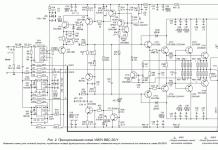
UMZCH VVS2011 scheme
The layout of printed circuit boards was carried out by a participant in many popular projects LepekhinV (Vladimir Lepekhin). It worked out very well).

UMZCH-VVS2011 board


ULF VVS-2011 amplifier board was designed for tunnel blowing (parallel to the radiator). The installation of transistors UN (voltage amplifier) and VK (output stage) is somewhat difficult, because. installation / dismantling has to be done with a screwdriver through holes in the PCB with a diameter of about 6 mm. When access is open, the projection of transistors does not fall under the PP, it is much more convenient. I had to tweak the board a bit.


In the new software did not take into account one point- this is the convenience of setting the protection on the amplifier board:

C25 0.1n, R42 * 820 Ohm and R41 1k all smd elements are located on the soldering side, which is not very convenient when setting up, because it will be necessary to unscrew and fasten the bolts of the PCB on the racks and transistors to the radiators several times. Offer: R42 * 820 consists of two smd resistors arranged in parallel, from here the proposal: we solder one smd resistor immediately, solder the other output resistor with a canopy to VT10, one lead to the base, the other to the emitter, we select it to the right one. Picked up, change the output to smd, for clarity:

Don't dream, act!
Experiments with various preamplifiers, volume and tone controls have shown that the best sound quality is provided with a minimum number of amplifying stages, with passive controls. In this case, adjustments at the input of the power amplifier are undesirable, since they lead to an increase in the level of non-linear distortions of the complex. This effect was recently discovered by the well-known developer of audio equipment Douglas Self.
Thus, the following structure of this part of the sound amplifying path emerges:
- passive bridge regulator of low and high frequencies,
- passive volume control
- preamplifier with a linear frequency response (AFC) and minimal distortion in the operating frequency range.
The obvious disadvantage of adjustments at the input of the preamplifier is that the deterioration of the signal-to-noise ratio is largely offset by the high signal level of modern sound reproduction devices.
Proposed preamplifier can be used in high quality stereo audio amplifiers. The tone control allows you to adjust the amplitude-frequency response (AFC) simultaneously on two channels in two frequency areas: lower and upper. As a result, the features of the room and acoustic systems, as well as the personal preferences of the listener, are taken into account.
And again a little history
The first contender for the role of a preamplifier with a tone control was D. Starodub's circuit (Fig. 1). But the design never "took root" in the power amplifier: careful shielding and a power supply with an extremely low ripple level (about 50 μV) were required. However, the main reason was the lack of sliding variable resistors.
Rice. 1. Diagram of a high-quality tone control block
Through trial and error, I came up with a simple preamplifier circuit (Fig. 2), with which, however, the sound reproduction system far exceeded the sound of mass-produced equipment, at least, that my friends and acquaintances had.

Rice. 2. Schematic diagram of one channel of the preamplifier for UMZCH S. Batya and V. Sereda
The pre-amplifier circuit of a stereophonic electrophone by Yu. Krasov and V. Cherkunov, which was demonstrated at the 26th All-Union Exhibition of Radio Amateurs-Designers, was taken as a basis. This is the left side of the circuit, including the tone controls.
The appearance of a cascade on transistors of different conductivity in the preamplifier (VT3, VT4) is associated with a discussion of amplifiers with the teacher of the laboratory of television technology at the Department of Radio Systems A. S. Mirzoyants, with whom I worked as a student. In the course of the work, linear cascades were needed to amplify the television signal, and Alexander Sergeevich reported that, according to his experience, top-down structures, as he put it, have the best characteristics, that is, amplifiers based on transistors of the opposite structure with direct connection. In the process of experimenting with UMZCH, I found out that this applies not only to television equipment, but also to sound amplification. Subsequently, I often used similar circuits in my designs, including a pair of field-effect transistor - bipolar transistor.
An attempt to use transistors of different structures in the first stage (composite emitter follower VT1, VT2) did not bring success, because with all the remarkable characteristics (low noise, low distortion), the circuit had a significant drawback - lower overload capacity compared to the emitter follower.
Pre-Amplifier Specifications:
Input resistance, kOhm = 300
Sensitivity, mV= 250
Depth of tone control, dB:
at a frequency of 40 Hz=± 15
at a frequency of 15 kHz=± 15
Depth of stereo balance adjustments, dB=± 6
Since new ideas arose during the design of amplifiers, I gave old designs to someone, or sold them at a fixed rate of watts of output power / ruble. On one of my trips to Leningrad, I took this amplifier with me to sell it to a friend of mine. Volodya said that this guy had a bunch of all kinds of Western equipment, and took the device to him for listening. In the evening he told me the results: the young man turned on the amplifier, listened to a couple of things and was so satisfied with the sound that he gave the money without a word.
To be honest, when I found out that the comparison would be made with imported equipment, I did not particularly hope that the amplifier would impress. In addition, it was not fully completed - there were no top and side covers.
Consider the schematic diagram of one channel of the preamplifier (Fig. 2). High-impedance volume (R2.1) and balance (R1.1) controls are installed at the input. From the middle output of the resistor R2.1 through the transition capacitor C2, the sound signal is fed to the composite emitter follower VT1, VT2, which is necessary for the normal operation of the passive tone control, made according to the bridge circuit. In order to eliminate the attenuation introduced by the tone block and amplify the signal to the required level, a two-stage amplifier based on transistors VT3, VT4 is installed.
The power supply of the pre-amplifier is unstabilized, from the positive arm of the power amplifier. The supply voltage is supplied to the stages VT3, VT4 through the filter R17, C10, C13, and to the input emitter follower - R8, C4. An important role is played by the VD1 diode: without it, it was not possible to completely eliminate the background of an alternating current with a frequency of 100 Hz at the output of the power amplifier.
Structurally, the pre-amplifier is made in a "line", all parts are installed on a printed circuit board, closed on top with a U-shaped screen made of steel 0.8 mm thick.
--
Thank you for your attention!
The calculation was made according to the following relations: R1 = R3; R2 = 0.1R1; R4 = 0.01R1; R5 = 0.06R1; C1[nF] = 105/R3[Ohm]; C2=15C1; C3=22C1; C4 = 220C1.
With R1=R3=100 kOhm, the tone block will introduce attenuation of about 20 dB at a frequency of 1 kHz. You can take variable resistors R1 and R3 of a different value, let, for definiteness, there were resistors with a resistance of 68 kOhm. It is easy to recalculate the values of fixed resistors and capacitors of the bridge tone control without referring to the program or table. 1: we reduce the resistance values of the resistors by 68/100=0.68 times and increase the capacitances of the capacitors by 1/0.68=1.47 times. We get R1 \u003d 6.8 kOhm; R3=680 Ohm; R4=3.9 kOhm; C2=0.033uF; C3=0.33uF; C4=1500 pF; C5 \u003d 0.022 uF.
For smooth tone control, variable resistors with an inverse logarithmic dependence (curve B) are required.
The program allows you to visually view the work of the designed tone control. Tone Stack Calculator 1.3(Fig. 9).

Rice. 9. Simulation of tone controls for the circuit shown in fig. 8
Program Tone Stack Calculator is designed to analyze seven typical schemes of passive tone controls and allows you to immediately show the frequency response when changing the position of the virtual controls.
Rice. 11. Schematic diagram of the tone block and preamplifier for the "student" UMZCH
An experimental test of several instances of operational amplifiers showed that even without a capacitor in the grounded branch of the negative feedback divider, the constant voltage at the output is a few millivolts. However, for reasons of versatility of application, isolation capacitors (C1, C6) are included at the input of the tone block and the output of the preamplifier.
Depending on the required sensitivity of the amplifier, the resistance value of the resistor R10 is selected from Table. 2. One should strive not for the exact value of the resistances of the resistors, but for their pairwise equality in the channels of the amplifier.
table 2 
▼ 🕗 25/02/12 ⚖️ 11.53 Kb ⇣ 149 Hello reader! My name is Igor, I'm 45, I'm a Siberian and an avid amateur electronics engineer. I came up with, created and maintain this wonderful site since 2006.
For more than 10 years, our magazine exists only at my expense.
Good! The freebie is over. If you want files and useful articles - help me!
--
Thank you for your attention!
Igor Kotov, editor-in-chief of Datagor magazine
The main disadvantage of a passive tone control is the low gain. Another drawback is that in order to obtain a linear dependence of the volume level on the angle of rotation, it is necessary to use variable resistors with a logarithmic control characteristic (curve "B").
The advantage of passive tone controls is less distortion than active ones (for example, Baksandal's tone control, Fig. 12).

Rice. 12. Active tone control P. Baksandala
As can be seen from the diagram shown in Fig. 12, the active tone control contains passive elements (resistors R1 - R7, capacitors C1 - C4) included in the 100% parallel negative voltage feedback of the operational amplifier DA1. The transmission coefficient of this regulator in the middle position of the R2 and R6 tone control sliders is equal to one, and variable resistors with a linear regulation characteristic are used for adjustment (curve "A"). In other words, an active tone control is free from the drawbacks of a passive tone control.
However, in terms of sound quality, this regulator is clearly worse than the passive one, which is noticed even by inexperienced listeners.
Rice. 13. Placement of parts on the printed circuit board
Items related to the right channel of the preamplifier are marked with a dash. The same marking is made in the printed circuit board file (with the *.lay extension) - the inscription appears when the cursor is moved to the corresponding element.
First, small-sized parts are installed on the printed circuit board: wire jumpers, resistors, capacitors, ferrite "beads" and a socket for the microcircuit. Lastly, terminal blocks and variable resistors are mounted.
After checking the installation, turn on the power and control the "zero" at the outputs of the operational amplifier. The offset is 2 - 4 mV.
If desired, you can drive the device from a sinusoidal generator and take characteristics (Fig. 14).

Rice. 14. Preamplifier characterization setup
--
Thank you for your attention!
Igor Kotov, editor-in-chief of Datagor magazine
Mentioned sources
1. Digest // Radiohobby, 2003, No. 3, pp. 10, 11.2. Starodub D. The block of tone controls for a high-quality bass amplifier // Radio, 1974, No. 5, p. 45, 46.
3. Shkritek P. Reference guide to sound circuitry. – M.: Mir, 1991, p. 150 - 153.
4. Shikhatov A. Passive tone controls // Radio, 1999, No. 1, p. 14, 15.
5. Rivkin L. Calculation of tone controls // Radio, 1969, No. 1, p. 40, 41.
6. Solntsev Yu. High-quality pre-amplifier // Radio, 1985, No. 4, pp. 32 - 35.
7. //www.moskatov.narod.ru/ (Program of E. Moskatov "Timbreblock 4.0.0.0").
Vladimir Mosyagin (MVV)
Russia, Veliky Novgorod
I have been interested in amateur radio since the fifth grade of high school.
Diploma specialty - radio engineer, Ph.D.
The author of the books "To a young radio amateur for reading with a soldering iron", "Secrets of amateur radio skill", co-author of a series of books "For reading with a soldering iron" in the publishing house "SOLON-Press", I have publications in the journals "Radio", "Instruments and Experimental Techniques", etc. .
Reader's vote

The article was approved by 70 readers.
To participate in the voting, register and enter the site with your username and password.
This article is a logical continuation of mine.
A pre-amplifier is supposed to be paired with the AF power amplifier, which provides for switching inputs, volume control, possibly timbres, and some other service capabilities.
The preamplifier must amplify the audio signal and match it with the power amplifier. Also, the inputs of the preamplifier must be matched to the source in terms of both voltage and resistance.
A good and simple circuit, a case and a non-standard solution for controlling adjustments are offered to you in this article.
Electronics
I will not bore you with a description of the choice and my thoughts. Here is the electrical circuit diagram:Excluded fragment. Our magazine exists on donations from readers. The full version of this article is only available
Relay 1 switches inputs. On relays 2 and 3, the tone controls are bypassed.
The balance was compiled according to the article “Stereo balance controllers” from the Radio magazine No. 1 for 1982, author V. Ezhikov, Zagorsk. A passive version of the scheme is presented.
It is better to analyze the calculation in something more flexible, so Microsoft Excel was used, where I made sure how and what works according to this scheme. As a result of the selection of elements, I got the following control curve:

Live also works fine, exactly as I wanted.
The input impedance of the preliminary in the middle position of the balance is about 25 kOhm. In fact, it floats a little, depending on the position of the balance and volume, but it does not fall below 15 kOhm.
There was another question, how to turn on the balance - before the volume control or after? After modeling, it turned out that before, the input resistance floats less.
OP1 understand why. Next is the timbre block, active, a complete copy of the timbre block used in N. Sukhov's “High-Quality Preamplifier”. The only thing is that I didn’t exactly select the containers, I put the ones that were. I picked up the variable resistors as best I could, I picked up the constants channel by channel, but I did not start the capacitance.
However, the changes in the frequency response in the middle position are very small. The oscilloscope shows almost the same rectangle (1kHz) as the input. And it's completely unnoticeable to the ear. The circuit was first drawn in the simulator RFSim99, which showed that I do not really need to select everything exactly - and so everything is quite good.
A graph of recent frequency response measurements (in RMAA) at the extreme positions of the tone knobs for clarity:

On the graph, the mid frequencies are shifted along the Y axis, this is due to different measurement levels (it doesn’t work otherwise, don’t pay attention), in fact, the middle is at 0 dB. I shot a graph on a regular laptop with a built-in sound card, so, you know, the picture is not ideal. But this is only at the edges, where the sound is already bad.
In the range of 100 - 10,000 Hz, everything is very good, but from 50 to 14,000 it is quite possible to measure, the unevenness is scanty.
Frequency response of the card itself, with closed input to output:

I also removed the curve in the middle position of the handles:

You can see the run-up in the channels at low frequencies, about 1 dB, these are variable resistors with a spread, but at high frequencies everything is even.
When direct is on (bypassing the tone block), the frequency response is the same as that of the card itself:

I also wanted to measure the distortion, but it was not possible. Some strangeness, when connecting the preliminary one, no harmonics are visible on the chart, although when checking the map, they are adequately displayed. About 0.021%.
The basis of everything is the chassis, everything is attached to it. Chassis made of solid pine 15 mm. I had a piece of the shield, why not? The chassis is blue in the photo. Below another (brown). So painted. A piece of iron with holes is a steel part of some device screwed to the chassis, such as a screen of something there.
The front panel is from the profile, the same as in the UMZCH, only I cut it a little in height. From the inside, a piece of wood is attached to the PP, everything is so conveniently screwed to this piece of wood. She is also blue in the photo.

And the front cover is inserted into the groove and is not attached to anything.


The chassis, back panel and sidewalls are connected by a piece of a silumin profile-casting from the Mayak tape recorder. This profile piece of white-gray color is what it is.

The chassis, sidewalls and rear wall made of aluminum and the wooden part of the front panel are attached to it. The very same metal part of the front is put on this piece of wood and fixed with screws from above and below (where it is not visible). Legs - as without legs - are screwed with self-tapping screws from the inside. The legs are wooden and easy to do. The rubber bands on the legs are cut from an old computer mouse pad.
A few self-tapping screws + 9 parts + legs, a little patience and - there is a case!
I'm talking about plastic black rings around the handles and the "Network" button. The fact is that for some time now I have fallen in love with handles inserted into the front panel through and through. To do this, I cut holes in the front panel larger than the diameter of the handles, and cover the edge of the hole with a ring machined from polystyrene or other plastic.
Rings are sharpened quite simply, almost on the knee. The only prerequisite is the presence of an electric rotation drive. For example, drills. The rest of the tools are easy to make from improvised means. A well-sharpened awl with a slightly cut edge can serve as a cutter. It is very important that the cutter be sharpened as sharp as possible, otherwise the polystyrene will melt and nothing will come out. For the same reason, one should not strive to remove a lot of material in one pass.
The blank of the ring is usually a piece of polystyrene from the back (if black is needed) panel of some equipment. Or arbitrary shape, or, if not laziness, in the form of a circle. Further, this workpiece is glued with a “moment” onto a wooden washer clamped into a drill chuck.
My own turner
Let's say there is a drill with a chuck and a way to fix the drill on the table. Let's say I seduced you, and you wanted to do like me.Then the easiest way is to fix a wooden blank into a drill in the following way: a metal bolt or a threaded stud is taken, a hat is cut off from the bolt, a hole is drilled in a piece of wood, approximately 1 mm smaller than the thread diameter, a wide chamfer is removed at the beginning of the thread. The bolt is clamped into the drill chuck and, like a tap, we cut the thread in the hole with force. In fact, it is squeezed out and rolled. That's it, the threaded stud is screwed into the wooden block until it stops and is clamped into the drill chuck.
So, the glue is dry and can be sharpened.
