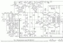
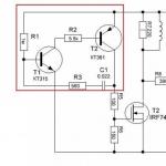
Here is another design using the 555 microcircuit. The device is a DC-AC voltage converter, which is designed to power energy-saving lamps from low voltage. The input voltage range is 8-18 Volts (optimal is 12 Volts). At the output of the transformer, a high-frequency alternating voltage of the order of 400 volts is formed. This is a simple and stable single-ended voltage converter that can be used in outdoor situations or in a car.
Despite its compact size and simplicity of design, the converter develops a fairly high power, which directly depends on the specific type of key used. With the use of a powerful field-effect transistor of the IRF3205 series, the power reaches 70 watts. In my case, the IRFZ48 transistor was used, with it the power is not more than 50 watts. It is not advised to raise the power to more than 70 watts, since it will be necessary to re-calculate the parameters of the pulse transformer.

The 555 timer works as a square wave generator. The impulses are amplified by a powerful field key. The transistor must be installed on the heat sink. The pulse transformer consists of only two windings. The primary winding consists of 7 turns. For the convenience of winding, 3 strands of wire with a diameter of 0.5 mm each were used. This solution saves space. Further, a step-up winding is wound over the primary winding. This winding consists of 80 turns of wire with a diameter of 0.2 mm. The winding can be wound in bulk without additional insulating layers.

The core was used from an old ATX power supply. To begin with, you need to unsolder the transformer from the block board and disassemble it. The halves of the ferrite are glued to each other tightly, so they need to be slightly warmed up. You need to warm carefully (with a lighter or a powerful soldering iron).

After, you need to remove all the windings and wind the ones you need. Such a single-cycle converter can power fairly powerful neon tubes up to 50 watts. The converter can also be used to power other electrical devices, including those designed for direct voltage, only in this case a rectifier is needed at the output.
The circuit of such a converter is not new, but it was redone and as a result of the rework, the number of radio components used was sharply reduced.
The circuit diagram of the converter for the LDS lamp is a simple blocking oscillator based on a powerful MJE13007 bipolar transistor, experience has shown that it does the best job, but it can be replaced with a more powerful one, such as MJE13009. Such transistors are often used in ATX computer power supplies. It is better to use a tuning resistor wire for a couple of watts, its value is 470 ohms, but it can deviate in one direction or another by 20% - this will not affect the operation of the converter.

A W-shaped ferrite transformer from the same computer power supply was used as a transformer. As a rule, such a transformer has 6 leads from the side of the step-down winding and one tap from the top. It is to this tap that we connect the plus power supply. The first and last output of the step-down winding, respectively, to the collector of the transistor and through the resistor to the base, there is no definite polarity here.

Next, we assemble the converter circuit for the lamp itself. The network winding of the transformer usually has 3 or 2 outputs, we connect the extreme outputs to a fluorescent lamp. For a soft start, you can connect a 400 volt 1 microfarad capacitor in series to the output, although it will work without it. The transistor needs to be mounted on a small heat sink.

We turn on the circuit and slowly rotate the tuning resistor until we achieve the maximum glow of the lamp - this is the base current limiting resistor, which simultaneously regulates the frequency. A well-assembled converter does not make unnecessary sounds and has a wide range of supply voltages from 3.5 to 12 volts (optimum - 6 volts).
Yu. Bearded, R. KOTURBAT, p. Rivna, Ivano-Frankivsk region
A resonant voltage converter differs from pulse and quasi-resonance converters by very low losses on switching transistors (1 ... 2% of the converted power). It can be used to power fluorescent lamps (LDS). The absence of a stabilizer makes it possible to power any LDS, including those with burnt out starting coils.
The main task in the design of the device was the use of a ready-made transformer from a TS-180 (TS-180-2) tube TV, since I really did not want to manufacture coil units. The second principle inherent in the homemade product is simplicity, as this provides the structure with high reliability and maintainability.
The circuit (Fig. 1a) is designed to power the LDS from the battery and charge it from the mains. You can even use batteries with one shorted bank by increasing the capacitances C1 and C2 to 0.5 microfarads.
To charge the battery, switch SA1 is set to the upper position according to the diagram. The mains voltage from the transformer T1 through the diodes VD1 ... VD4 is applied to the battery. When switching to operating mode (LDS power supply), SA1 is set to the lower position according to the diagram. Sometimes, to start very old lamps, a circuit is required that increases the potential of the base VT1 and VT2 (Fig. 1b).
The voltage converter consists of two blocking generators operating synchronously. The circuit formed by the capacitance of the base junctions of the transistors and the transformer winding enters into resonance with another circuit formed by the capacitance of the lamp and the secondary winding. The frequency of resonant oscillations is 100...150 kHz. By reducing the capacitance of the capacitors to 0.1 μF, using only one (it is possible with a short circuit in the turns!) Coil, you can make a converter according to the circuit shown in Fig. 2.

Details. Transistors in the circuits should only be powerful, in metal cases, for example, KT805. With an increase in the supply voltage above 12.8 V, the efficiency of the circuit decreases slightly, which leads to heating of the transistors. In the circuit shown in Fig. 1, transistors and their corresponding diodes can be placed on two radiators. The other two diodes can be screwed directly onto the chassis. The heating of transistors can be reduced by reducing the capacitance of the capacitors, which makes it easier to start the lamp, but reduces its brightness. As HL1, any fluorescent lamp (6 ... 40 W) is used. If the capacitors get hot, replace them with better quality ones with less leakage. Schemes are not critical to details.
As T1, in addition to TS-180, you can use TS-160 and other similar transformers. When using only one empty coil (Fig. 2), it is not required to fill it with a ferrite "scrap", as described in. Transistors can also be p-n-p conductivity, if you change the polarity of the diodes and batteries.
Literature
1. Konovalov E. Quasi-resonant voltage converter. - Radio, 1996, N2, p.52.
2. Bearded Yu. Daytime from the accumulator. - House, garden, vegetable garden, 1998. N4.
3. Bearded Yu. Daytime from the accumulator. - Electrician, 2000, N4.
Converter 12V - 220V for powering LDS from a computer PSU.
[email protected]The converter is used to power fluorescent lamps (LDS) with electronic ballast. Electronic ballasts are separate devices that replace low-frequency chokes. As a rule, such ballasts are in the fittings of finished lamps on LDS. The converter is guaranteed and reliably works with ballasts of both powerful and "weak" lamps.
The converter is also used to power the "economical" base-type LDS; for autonomous, bright and economical lighting of the house, garage, car interior.
This is a push-pull pulse converter assembled on a TL494 PWM controller (domestic analogue 1114EU4), which makes the circuit quite simple. At the output are high-performance rectifier diodes doubling the voltage. The output, of course, is a constant voltage, but for electronic ballasts, a constant voltage and the polarity of switching on are not relevant, because. in the ballast circuit, there is a diode bridge at the input.

As a step-up transformer, the converter uses a ready-made high-frequency transformer from the power supply unit (PSU) of the computer, which, like almost all the parts used in this circuit, can be taken from a faulty or unnecessary Unit, both AT and ATX, in our converter it will work in as a booster.
The transformer can also be wound independently: For this, we find a suitable ferrite ring (outer diameter of about 20-30 mm). The ratio of turns is approximately 1:1:20, where 1:1 is the two halves of the primary winding (10 + 10 turns), and 20 is, respectively, the secondary 200 turns. First, the secondary is wound - evenly 200 turns with a wire with a diameter of 0.3-0.4 mm. Then evenly two halves of the primary winding (we wind 10 turns, make an average tap, then we wind the remaining 10 turns in the same direction). For half-windings, a stranded, silver-plated mounting wire with a diameter of 0.8 mm was used (you can not drive and use another wire, but stranded and soft is better).
Another option for manufacturing (reworking) a transformer is to purchase a so-called. "electronic transformer" for 12 volt halogen ceiling and furniture lighting (in lighting equipment stores). It has a suitable transformer on the ring. It is only necessary to remove the secondary winding, which is a dozen turns. And the half-windings can be wound differently - we fold a piece of wire (calculate the length) in half and wind it with a double-folded wire; we cut the middle of the wire (place of inflection) - we get the so-called. two ends (or two beginnings) of windings. We solder the beginning of the other to the end of one wire - we get a common point of half-windings.
Transistors are powerful MOSFETs (metal-oxide-semiconductor) field-effect transistors, which are characterized by faster response times and simpler control circuits. IRFZ44N, IRFZ46N, IRFZ48N work equally well (the larger the number, the more powerful and expensive).
The converter uses HER307 diodes (304, 305, 306 are suitable). Domestic KD213 work perfectly (more expensive and larger).
Capacitors at the output can be of smaller capacity, but with an operating voltage of 200V. Used capacitors from the same computer PSU with a diameter of not more than 18 mm (or edit the PCB drawing).
Install the microcircuit on the panel; it will make life easier.
FORMING comes down to correct ( carefully) installing the chip in the panel. If it doesn't work, check for 12V supply voltage. Check ornot swappedR1 and R2. Everything should work.
The radiator is not required, because. continuous operation does not cause noticeable heating of the transistors, but if there is a desire to put it on a radiator, then, attention, do not short-circuit the flanges of the transistor cases through the radiator. Use insulating gaskets and bushing washers all from the same computer PSU. Although, for the first start-up, the radiator may not hurt; at least the transistors will not immediately burn out in the event of wiring errors or short circuits at the output, or if a 220V incandescent lamp is "accidentally" connected.
The power supply of the circuit must be convincing, tk. the current consumption of one copy of the "economical" LDS from a sealed acid battery was 1.4 A at a voltage of 11.5V; total 16 W (although the packaging of the lamp says 26 W).circuit overload protection and rewrites can be implemented through a fuse and a diode at the input.
Be careful!There is a high voltage at the output of the circuit and it can hit very seriously. Capacitors hold a charge for more than a day. There are no discharge circuits at the output. shorting is not allowed, discharge either with a 220V incandescent lamp or through a 1 mΩ resistance.
Photo converter:


For the converter, depending on the dimensions of the transformer, the author made two drawings of the printed circuit board, (the size of the boards is 50x55 mm).

Board 1. () Board 2. (download in Sprint Layout format)
CONVERTER 12V - 220V USING A STANDARD TRANSFORMER.


The proposed converter circuit is easy to manufacture, made on a minimum number of parts. The device does not have any features, it does not need adjustment. The converter can be used as a backup power source. The transformer is used ready-made - from a conventional power supply, but in reverse connection. It has two windings for 9V with a maximum load current of 1.2 ... 1.5A and a network winding for 220V.

The voltage converter provides mains voltage 220V 50 Hz at a load of up to 5 W. It consists of a master oscillator with a frequency of 100 Hz and a divider trigger on the IC O, powerful MOS switches VT1 VT2 and a 6-watt network transformer with secondary windings 2x9V, included as a boost. When the load increases to the maximum, the output voltage decreases from 250V to 200V, which is acceptable for most devices. In this case, the current consumed by the device increases from 80 to 630 mA.
More schemes:


The transformer is wound on a ferrite rod (any) with a diameter of 6-8 mm, a length of 60 mm, wrapped with electrical tape.
I - 45 vit. with a wire with a diameter of 0.5 mm (or so)
II - 25 vit. 0.25mm (or so)
III - 600 vit. 0.25mm (or so)


Single-cycle pulse voltage converter 12-220V.

This voltage converter allows you to connect a load with a power of up to 100W. At idle, the current consumed by the converter does not exceed 0.5A. Input voltage range 9-15v. The operating frequency of the converter is about 20 kHz.
The transformer is made of two magnetic cores folded together from ferrite grade M2000NM1, size K32x20xb. The winding data are shown in the table.
|
Col .in itkov |
||
|
PEL0 .8...1.0 |
||
|
PEL0,25 |
||
|
PEL0,25 |
In the manufacture of a transformer, the secondary winding is first wound. Winding is performed turn to turn, in one layer, followed by insulation with fluoroplastic or other insulating material. The primary winding is wound with two wires at the same time (evenly distributing the turns on the magnetic circuit).
CONVERTER 12V/220V.
Converter (in other words, DC / DC converter) you can connect standard network chargers from mobile phones to it. Preliminary calculations showed that, taking into account the losses from two conversions, the overall efficiency of the system will be about 65% (assuming the efficiency of each of the devices is 80%, which is typical for low-power pulse converters).


The whole device is assembled on a printed circuit board with dimensions of 40x60 mm (Fig. 2), the appearance is shown in the photo at the beginning of the article. Output transformer: core 2 rings K20x12x6 ferrite 2000-NM1, step-up winding 180 turns with PELSHO 0.12 wire (wound first), primary winding 13 turns with doubled PEL 0.6 wire. With this core at the selected frequency, you can get a power of about 25 ... 30 W (one ferrite ring is enough for this circuit). The core section is increased in order to reduce the number of turns in the windings.
 The scheme does not require settings.
You can check the quality of the wound transformer. When an input supply voltage of 12V is applied, the current consumption at "idle" with the connected resistor R6 must be 40 ... 45mA, the output voltage is 200V.
If so, then everything worked out. If the idle current is greater, check the frequency with an oscilloscope at pin 9 or 10 (oscillation period 40 µs). If everything came together, then the reason is in the transformer: the short circuit of the turns, the wrong core material.
In operating mode with a connected charger and telephone, the current consumed from the 12V network is 300 ... 400 mA (with a discharged battery in the phone, the current is higher), the voltage at the converter output in this mode is -160 ... 170V.
Sources:
S. Yu. Stebenev; T. Nosov
http://radio-hobby.org/
---->
---->
Voltage converter for fluorescent lamp
I. NECHAYEV, KurskThis converter can be used to power fluorescent lamps up to 20 W from a battery or other autonomous source with a voltage of 6 ... 12 V, for example, in field conditions. Its circuitry, similar to that widely used in many imported battery-operated portable fluorescent lamps, is shown in Fig. 1.

The basis of the converter - a blocking generator based on a transistor VT1 and a transformer T1 - generates short pulses with a frequency of 30 ... 40 kHz and an amplitude of 400 V, which are fed to a fluorescent lamp EL1. Due to the high frequency of pulses and the inertia of the phosphor, the flashing of the lamp is completely imperceptible.
When adjusting the frequency using a variable resistor R2, the duration of the pulses remains constant. Their duty cycle changes, and with it, the brightness of the lamp glow. The greater the resistance is entered, the lower the frequency and the greater the duty cycle, the lower the brightness of the lamp and the current consumed from the power source (for example, a car battery). When testing the converter with an F13W lamp, the current was 70 mA at minimum and 800 mA at maximum brightness.
The regulator is assembled on a single-sided printed circuit board 35x85 mm in size, a fragment of which is shown in fig. 2.

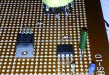
On the rest of it are (glued or fixed with screws) a transformer T1 and a transistor VT1 with a heat sink. The body of the variable resistor R2 after soldering the leads is also fixed with glue. The appearance of the mounted board is shown in fig. 3.

It is placed in a housing of suitable size made of insulating material, bringing the axis of the variable resistor into the hole on the front wall. The EL1 lamp can be installed in standard fittings or fittings made independently from improvised materials.
Instead of the KT841A transistor, you can use KT805A or KT847A. The heat sink area must be at least 15 cm2.
The magnetic circuit of the transformer T1 is armored B30 made of M1500NM3 ferrite. It is assembled with a non-magnetic gap of 0.2 ... 0.5 mm. Winding I - 24 turns of PEV-2 0.38 ... 0.41 mm (in two wires), II - 7 turns of the same, but single wire, III - 190 turns of PEV-2 wire 0.18 ... 0 .2 mm. The latter is reliably isolated from other windings and the magnetic circuit with varnished cloth or insulating tape.
Any 4...20 W fluorescent lamps can be connected to the converter, including those with burnt out filaments. If the lamp power is less than 10 W, the number of turns of winding III should be reduced.
The converter will be able to operate at a lower (up to 6 V) supply voltage if the number of turns of the winding II is reduced in proportion to the voltage. However, its efficiency is noticeably reduced, so it is not recommended to use lamps with a power of more than 10 W in this case.
When setting up the converter, resistor R1 is selected in such a way that in the right (according to the diagram) position of the variable resistor R2 engine, the brightness of the lamp glow is subjectively perceived as nominal, corresponding to its connection to the network according to a typical circuit with a "ballast" choke. If moving the slider to the opposite position reduces the brightness insufficiently or excessively, the value of the variable resistor should be increased or decreased accordingly.
