From the author: hello dear readers! The ventilation system is a very important part of the arrangement of any home. After all, it is thanks to her that you breathe fresh, not stagnant air. This has a significant positive impact on both the health of the people living in the house and their level of comfort.
But all these advantages are relevant, of course, for those cases when it works correctly. In particular, its performance is very important, which should be sufficient for a particular building. To ensure the required indicator, it is important to choose the right equipment of the required power, as well as to calculate the cross section of the ventilation duct.
The need for calculations
All calculations for arranging ventilation both in a private house and in an apartment must be performed as carefully as possible. This is due to the fact that poor-quality air exchange can lead to rather serious consequences. Among them are:
- discomfort of people living in the house. It's hard to be in a stuffy room. In addition, all unpleasant odors stagnate, because they simply do not have a chance to go outside. As a result, they are impregnated with both furniture and room decoration. It is clear that such a dwelling does not cause pleasant sensations;
- harm to health. Exhaust air contains large amounts of carbon dioxide. If you stay in such an atmosphere for a long time, then this does not affect the body in the best way. People experience rapid fatigue, headache often begins. And the general state of health worsens sooner or later;
- increased levels of humidity. To adjust it, high-quality air exchange is necessary, and when there are problems with the latter, the result becomes obvious. The consequence of this state of affairs is unpleasant condensation on the windows, and breathing in a room with a high level of humidity is harder than usual. In addition, this situation will lead to the appearance of mold and fungus on the walls. Getting rid of such "neighbors" is very, very difficult. But it’s impossible not to get rid of it - the spores secreted by mold enter the lungs of people living in the house. This provokes the development of various infections, some of them are life-threatening.
Carrying out calculations

Now that you are convinced of the extreme necessity of calculations, you can talk about how they are made. But first of all, it is worth understanding what factors affect the final indicator. Actually, they all belong to the type of the duct itself.
Varieties of air ducts
Air ducts differ in two ways. The first is the material from which this structural element is made. There are quite a few modern options out there. Air ducts can be:
- steel (black or stainless metal);
- plastic;
- aluminum;
- tissue;
- tin.
In this case, the structure of the material is important. The rougher the surface inside the pipe, the more force the air must exert to travel along the appropriate route, as the resistance increases. This factor directly affects the required cross-sectional index.
The second parameter is the shape of the duct. It can be round, square, oval or rectangular. Each form has certain advantages and disadvantages. For example, for round varieties, less material is needed for manufacturing, which is beneficial from an economic point of view. Rectangular air ducts may not be too large both in height and in width - all the same, their cross-sectional area will be kept at the required level.
Payment Methods
Strictly speaking, the calculations necessary for the arrangement and other types of ventilation should be carried out by specialized organizations that have the appropriate license. Professionals have a full set of necessary knowledge and experience. It is often difficult for an ordinary person to understand how to correctly calculate one or another parameter.
But the desire for savings and the love of independent work have not gone away, so many still prefer to figure this issue out. If you belong to this category of people, then be patient and have a notebook with a pen.
There are two ways to calculate the cross section of a duct. One is based on allowable speeds, the other is based on constant pressure loss. both of them give the required parameter, but the first one is the simpler one. So it's better to start with him.
All buildings and premises are divided into different categories. Depending on the type of building, a certain normalized value of the maximum allowable speed is provided for it, both for the main duct and for the branches coming from it.

Accordingly, for the calculations you will need these standard indicators. It is also necessary to have a plan at hand indicating all the routes included in it and the types of equipment installed. It is on these blanks that the process of further work will be based.
As for the normalized indicators of the maximum allowable speed, they can be summarized in the following list:
- industrial premises - for the main highway, the speed is from 6 to 11 meters per second, for branches from 4 to 9 meters per second;
- office premises - for the main line from 3.5 to 6 m/s, for branches from 3 to 6.5 m/s;
- residential premises - for the main line from 3.5 to 5 m / s, for branches from 3 to 5 m / s.
These standards are due to the fact that the air flow rate exceeding them will create a high level of noise, which will make people in the room very uncomfortable.
So, the calculation process is reduced to the following steps.
- A diagram of the ventilation system is drawn up. It indicates each highway and the branches coming from it. All equipment that is installed in the ducts is also indicated. It includes diffusers, valves, grilles and the like. You should also mark all the turns of the duct.
- Next, you need to calculate how much air should enter the room every hour. This parameter depends primarily on the number of people in the room for a long time. The volume of air per person is approved by the norms of SNiP. They indicate that in a room where natural ventilation is not performed, the air consumption per person is at least 60 m 3 / h. If we are talking about the bedroom, then there the indicator is less - only 30 m 3 / h. This is due to the fact that during sleep a person processes a smaller amount of oxygen. In general, for the calculation it is necessary to take into account the number of people staying in the house for a long time, and multiply this number by the indicator established by the standards. If you regularly gather large companies, then you don’t need to focus on them - the standards are relevant only for a long stay. In such a case, you can get a VAV system that will help regulate the air exchange processes between rooms during the reception.
- After you have received both indicators - that is, the maximum allowable speed and the required volume of air entering the room - you can take on the calculation of the estimated area of \u200b\u200bthe duct. To do this, you can use a scheme called a nomogram. As a rule, it comes with a flexible duct pipe. If it is not in paper form, then you can search on the website of the company that released this product. In addition to the nomogram, you can calculate the required indicator manually. To do this, you need to substitute the available parameters in the formula: Sc \u003d L * 2.778 / V. Under Sc is meant, in fact, the same area of the duct. It will be expressed in square centimeters, since this value is most convenient to work with. The letter L means the previously calculated required volume of air entering the room through the duct. The letter V is the speed of air flow in a particular line. The number 2.778 is the factor needed to accommodate different types of units: m 3 /h, m/s and cm 2 .
- Now you can take on the calculation of the actual cross-sectional area of the duct. There are two formulas for this. Which one to use depends on the shape of the pipe. For round duct: S=π*D²/400. Under S is meant the calculated cross-sectional area, under D is the diameter of the pipe. For a rectangular version, the formula is as follows: S=A*B/100. In this case, the letter A means the width of the pipe, and the letter B - the height. The dimensions of the sides of the rectangle and the diameter of the circle are indicated in millimeters.
Thus, it is necessary to calculate the corresponding indicator for each section of the ventilation system: both for the main highways and for additional routes. Based on these indicators, you can proceed to the calculation of the required power of the equipment installed for forced air inflow or outflow.

For proper selection of a built-in fan, you will also need to know the pressure drop in the ventilation system. This parameter can be calculated using the same nomogram that you used to determine the volume of air.
Dear readers! All calculations necessary for the arrangement of any type of ventilation system, in principle, are not so complicated. But they require a fairly large amount of time, as well as careful attention. A miscalculation can lead to the fact that you install an air duct that is too narrow or wide, or you select ventilation equipment with a capacity that does not match the needs of the room.
Therefore, if you are not confident in your abilities or are firmly aware of the existing problems with physics and mathematics, then it is better to turn to specialists. This will not hit the budget too hard, but in return it will guarantee that the ventilation system will work with proper functionality.
If you are still determined to carry out calculations on your own, then also watch the video instruction, the link to which is left just below. Approach the matter carefully and carefully, then you will succeed perfectly. Good luck to you, comfort to your home! See you soon!
The efficiency of ventilation systems depends on the correct selection of individual elements and equipment. The calculation of the air duct area is carried out in order to ensure the required frequency of air changes in each room, depending on its purpose. Forced and natural ventilation require separate algorithms for design work, but have common directions. When determining the resistance to air flow, the geometry and material of manufacture of air ducts, their total length, kinematic diagram, and the presence of branches are taken into account. Additionally, heat energy losses are calculated to ensure a favorable microclimate and reduce the cost of maintaining the building in the winter.
The calculation of the cross-sectional area is performed on the basis of data on the aerodynamic calculation of air ducts. Taking into account the obtained values, the following is performed:
- Selection of the optimal dimensions of the cross sections of the air ducts, taking into account the normative permissible speeds of the air flow.
- Determination of the maximum pressure loss in the ventilation system, depending on the geometry, speed and features of the duct layout.
The sequence of calculation of ventilation systems
1. Determination of calculated indicators of individual sections of the overall system. The sections are limited by tees or technological dampers, the air flow along the length of the entire section is stable. If there are branches from the site, then their air flow is summed up, and the total is determined for the site. The obtained values are displayed on the axonometric diagram.
2. Choice of the main direction of the ventilation or heating system. The main section has the largest air consumption among all allocated during the calculations. It should be the longest of all consecutive individual sections and branches. According to regulatory documents, the numbering of sections begins with the least loaded and continues with increasing air flow.
Approximate diagram of the ventilation system with designations of branches and sections
3. The parameters of the sections of the calculated sections of the ventilation system are selected taking into account the speeds recommended by the standards in the air ducts and louvered grilles. According to state standards, the air velocity in main pipelines is ≤ 8 m/s, in branches ≤ 5 m/s, in louvres ≤ 3 m/s.
Calculations for the ventilation system are carried out taking into account the existing preconditions.
Total pressure loss in air ducts:
![]()
Calculation of rectangular ducts for pressure loss:
R - specific friction losses on the air duct surface;
L is the length of the duct;
n - correction factor depending on the roughness of the air ducts.
Specific pressure losses for circular sections are determined by the formula:
λ is the coefficient of hydraulic friction resistance;
d is the diameter of the duct section;
P d - actual pressure.
To calculate the coefficient of friction resistance for a circular pipe section, the following formula is used:

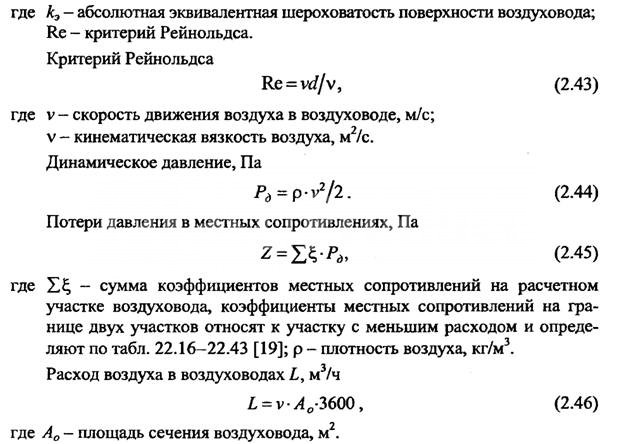
During calculations, it is allowed to use tables in which, based on the above formulas, practical friction losses, dynamic pressure indicators and air flow rates for various flow rates for are determined.
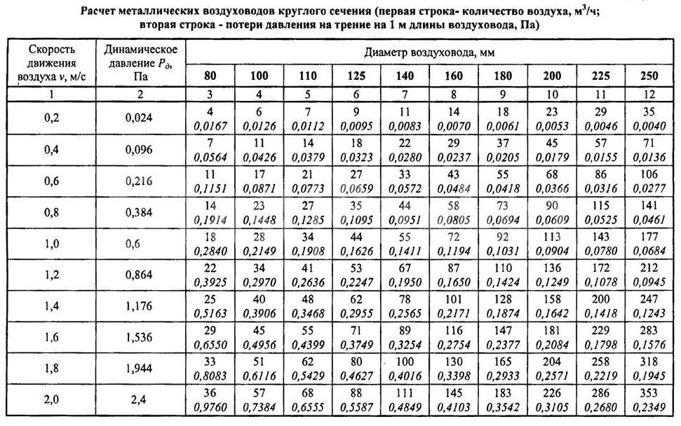


It must be borne in mind that the indicators of the actual air flow in rectangular and round ducts with the same cross-sectional area are not the same even with complete equality of the air flow speeds. If the air temperature exceeds +20°C, then correction factors for friction and local resistance must be used.
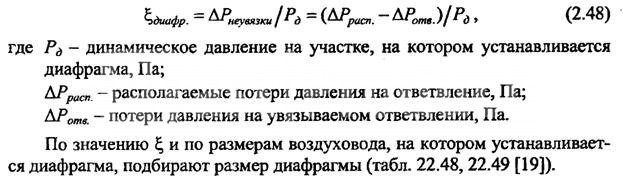
The calculation of the ventilation system consists of the calculation of the main line and all branches connected to it. In this case, it is necessary to achieve a position so that the air speed constantly increases as it approaches the suction or discharge fan. If the duct scheme does not allow taking into account branch losses, and their values do not exceed 10% of the total flow, then it is allowed to use the diagram for overpressure damping. The coefficient of resistance to the air flow of the diaphragm is calculated by the formula:
The above duct calculations are suitable for the following types of ventilation:
- Exhaust. It is used to remove exhaust air from industrial, commercial, sports and residential premises. In addition, it can have special filters for cleaning the air emitted from dust or harmful chemical compounds; they can be mounted inside or outside the premises.
- supply. Prepared (heated or purified) air is supplied to the premises, it may have special devices to reduce noise levels, automate control, etc.
- Supply/exhaust. A complex of equipment and devices for supplying/removing air from premises for various purposes may have heat recovery units, which significantly reduces the cost of maintaining a favorable microclimate in the premises.
The movement of air flows through the ducts can be horizontal, vertical or angular. Taking into account the architectural features of the premises, their number and size, air ducts can be installed in several tiers in one room.
Calculation of the cross-sectional area of the pipeline
After the speed of air movement through the ducts is determined, taking into account the required exchange rate, it is possible to calculate the parameters of the cross-section of the air ducts according to the formula S = R\3600v, where S is the cross-sectional area of the air duct, R is the air flow rate in m 3 / hour, v is the speed of air movement flow, 3600 - time correction factor. The cross-sectional area allows you to determine the diameter of a round duct using the formula:
![]()
If a square duct is installed in the room, then it is calculated by the formula d e \u003d 1.30 x ((a x b) 0.625 / (a + b) 0.25).
d e - equivalent diameter for a round duct in millimeters;
a and b are the lengths of the sides of the square or rectangle in millimeters. To simplify the calculations, use the conversion table No. 1.
Table No. 1

To calculate the equivalent diameter of oval ducts, use the formula d = 1.55 S 0.625 /P 0.2
S is the cross-sectional area of the oval duct;
P is the perimeter of the pipe.
The cross-sectional area of an oval pipe is calculated by the formula S \u003d π × a × b / 4
S is the cross-sectional area of the oval duct;
a = large diameter oval duct;
b = smaller diameter of the oval duct.
Selection of oval or square air ducts according to the speed of the air flow To facilitate the selection of the optimal parameter, the designers calculated ready-made tables. With their help, you can choose the optimal size of air ducts of any section, depending on the frequency of air exchange in the premises. The frequency of exchange is selected taking into account the volume of the room and the requirements of SanPin.

Calculation of parameters of air ducts and natural ventilation systems In contrast to forced air supply/removal, for natural ventilation, indications of the difference in pressure outside and inside the premises are important. The drag calculation and direction selection must be done in such a way as to guarantee a minimum flow pressure loss.
When calculating, the existing gravitational pressures are linked with the actual pressure losses in vertical and horizontal air ducts.

Classifications of initial data during the calculation of the cross section of air ducts During calculations, it is necessary to take into account the requirements of the current SNiP 2.04.05-91 and SNiPa 41-01-2003. The calculation of ventilation systems according to the diameter of the air ducts and the equipment used should provide:
- Normalized indicators for air purity, exchange rate and indoor microclimate indicators. The power of the installed equipment is calculated. At the same time, the level of noise and vibration cannot exceed the established limits for buildings and premises, taking into account their purpose.
- The systems must be maintainable, during the scheduled maintenance work, the technological cycle of the enterprises should not be disturbed.
- In rooms with an aggressive environment, only special air ducts and equipment are provided that exclude sparking. Hot surfaces must be additionally insulated.
Standards for design conditions for determining the cross section of air ducts
The calculation of the air duct area should provide:
- Proper conditions for cleanliness and temperature conditions in the premises. For rooms with excess heat, ensure its removal, and in rooms with a lack of heat, minimize the loss of warm air. At the same time, it is necessary to adhere to the economic feasibility of fulfilling these conditions.
- The speed of air movement in the premises should not impair the comfort of people staying in the premises. This takes into account the obligatory air purification in the working areas. In the jet of air entering the room, the speed of movement Nx is determined by the formula Nx = Kn × n. The maximum inlet air temperature is determined by the formula tx = tn + D t1, and the minimum by the formula tcx = tn + D t2. Where: nn, tn - normalized air flow rate in m / s and air temperature at the workplace in degrees Celsius, K \u003d 6 (air velocity transition coefficient at the outlet of the duct and in the room), D t1, D t2 - maximum allowable deviation temperature.
- The maximum concentration of harmful chemical compounds and suspended particles according to GOST 12.1.005-88. Additionally, you need to take into account the latest decisions of the State Supervision.
- Outside air parameters. They are regulated depending on the technological features of the production process, the specific purpose of the structure and buildings. Indicators of the concentration of explosive compounds and substances must meet the requirements of fire-fighting state authorities.
Installation of ventilation systems with forced air supply / removal should be done only in cases where the characteristics of natural ventilation cannot provide the required parameters for cleanliness and temperature conditions in the premises or buildings have separate zones with a complete absence of natural air inflow. For some rooms, the area of the air ducts is selected in such a way that the backwater is constantly maintained in the rooms and the supply of outside air is excluded. This applies to pits, basements and other premises in which there is a possibility of accumulation of harmful substances. Additionally, air cooling must be present at workplaces that have a thermal exposure of more than 140 W/m 2 .
Requirements for ventilation systems If the calculated data on ventilation systems lower the temperature in the premises to + 12 ° C, then it is imperative to provide for simultaneous heating. Heating units of the appropriate power are connected to the systems in order to bring the temperature values up to those normalized by state standards. If ventilation is installed in industrial buildings or public premises in which people constantly stay, then at least two supply and two exhaust constantly operating units must be provided. The size of the area of the air ducts must provide the calculated value of air flows. For connected or adjacent rooms, it is allowed to have two exhaust systems and one supply system, or vice versa.
If the premises must be ventilated around the clock, then backup (emergency) equipment must be connected to the installed air ducts. Additional branches should be taken into account, a separate calculation of the area is made for them. A standby fan can be omitted only if:
- After the failure of the ventilation system, it is possible to quickly stop the work process or take people out of the room.
- The technical parameters of emergency ventilation fully meet the requirements for cleanliness and air temperature in the premises.
General requirements for air ducts The calculation of the final parameters of the air ducts should provide for the possibility of:
- Mounting of fire dampers in vertical or horizontal position.
- Installations on interfloor platforms of air locks. The design features of the devices must ensure that the regulatory requirements for the emergency shutdown of individual branches of the ventilation system and the prevention of the spread of smoke or fire throughout the building are met. In this case, the length of the section on which the gates are attached should not be less than two meters.
- No more than five air ducts can be connected to each floor manifold. The connection node creates additional resistance to air flow, this feature must be taken into account when calculating the dimensions.
- Installation of automatic fire alarm systems. If the alarm drive is mounted inside the duct, then when determining its optimal diameter, the reduction in the effective diameter and the appearance of additional resistance to the air flow due to turbulence should be taken into account. The same requirements are put forward when installing check valves that prevent the flow of harmful chemical compounds from one production facility to another.
Air ducts made of non-combustible materials must be installed for ventilation systems with suction of flammable products or with temperatures above +80°C. The main transit sections of ventilation should be metal. In addition, metal air ducts are mounted in attics, technical rooms, basements and undergrounds.
The total air loss for fittings is determined by the formula:
![]()
Where p is the specific pressure loss per square meter of the expanded section of the duct, ∑Ai is the total expanded area. Within one installation scheme of the ventilation system, losses can be taken from the table.
During the calculation of the dimensions of the air ducts, in any case, engineering assistance will be needed, the employees of our company have enough knowledge to solve all technical issues.
To create a favorable microclimate in industrial and residential premises, it is necessary to install a high-quality ventilation system. Particular attention must be paid to the length and diameter of the pipe for natural ventilation, since the efficiency, performance and reliability of air ducts depend on the correct calculations.
What are the requirements for ventilation pipes?
The main purpose of the duct for natural ventilation is to remove exhaust air from the room.
When laying systems in homes, offices and other facilities, the following points must be considered:
- the diameter of the pipe for natural ventilation must be at least 15 cm;
- when installing in residential premises and at food industry facilities, anti-corrosion characteristics are important, otherwise metal surfaces will rust under the influence of high humidity;
- the lighter the weight of the structure, the easier the installation and maintenance;
- performance also depends on the thickness of the duct, the thinner, the greater the throughput;
- fire safety level - no harmful substances should be released during combustion.
If you do not follow the standards (norms) when designing, installing and choosing the material of manufacture and the diameter of PVC ventilation pipes or galvanized steel, then the air in the rooms will be “heavy” due to high humidity and lack of oxygen. In apartments and houses with poor ventilation, windows often fog up, walls in the kitchen smoke, and fungus forms.
What material to choose an air duct?
There are several types of pipes on the market, differing from each other in the material of manufacture:
Advantages of plastic pipes:
- low cost when compared with air ducts made of other materials;
- anti-corrosion surfaces do not need additional protection or treatment;
- ease of maintenance, when cleaning, you can use any detergent;
- a large selection of PVC pipe diameters for ventilation pipes;
- simple installation, also, if necessary, the structure can be easily dismantled;
- dirt does not accumulate on the surface due to smoothness;
- when heated, there is no release of harmful and toxic substances for human health.

Metal air ducts are made of galvanized or stainless steel, when considering the characteristics, the following advantages can be distinguished:
- galvanized and stainless pipes are allowed to be used at facilities with high humidity and frequent temperature changes;
- moisture resistance - structures are not subject to the formation of corrosion and rust;
- high heat resistance;
- relatively small weight;
- easy installation - basic knowledge required.

Aluminum foil is used as a material for the manufacture of corrugated air ducts. Main advantages:
- during installation, a minimum number of connections is formed;
- ease of dismantling;
- if necessary, the pipeline is placed at any angle.
Advantages of fabric structures:
- mobility - easy to install and dismantle;
- there are no problems during transportation;
- lack of condensate under any operating conditions;
- low weight facilitates the fastening process;
- no additional insulation required.
What are the types of air ducts?
Depending on the scope and direction of use, not only the diameters of PVC pipes are selected, but also the shape:

- Spiral forms are distinguished by increased rigidity and attractive appearance. During installation, the connections are made using a cardboard or rubber seal and flanges. Systems do not need isolation.
Advice! If there is no experience in this area, then in order to save your own money and time, it is better to immediately contact the specialists, since it will be very problematic to calculate the diameter of the pipe for ventilation, taking into account the air flow, and to carry out the installation yourself.
- For residential buildings (country and country houses), flat forms are ideal due to the following advantages:
- if necessary, round and flat pipes can be easily combined;
- if the dimensions do not match, then the parameters are easily adjusted using a construction knife;
- structures differ in relatively small mass;
- tees and flanges are used as connecting elements.
- Installation of flexible structures takes place without additional elements for connection (flanges, etc.), which greatly simplifies the installation process. The material used is laminated polyester film, woven fabric or aluminum foil.
- Round air ducts are more in demand, the demand is explained by the following advantages:
- minimum number of connecting elements;
- simple operation;
- air is well distributed;
- high rates of rigidity;
- simple installation work.
The material of manufacture and the shape of the pipes are determined at the stage of development of project documentation, a large list of items is taken into account here.
How is the diameter of the ventilation pipe determined?
On the territory of Russia, there are a number of SNiP regulatory documents that say how to calculate the diameter of a pipe for natural ventilation. The choice is based on the frequency of air exchange - a determining indicator of how much and how many times per hour the air in the room is replaced.
First you need to do the following:
- the volume of each room in the building is calculated - you need to multiply the length, height and width;
- air volume is calculated by the formula: L=n (normalized air exchange rate)*V (room volume);
- the obtained indicators L are rounded up to a multiple of 5;
- the balance is drawn up so that the exhaust and supply air flows coincide in the total volume;
- the maximum speed in the central air duct is also taken into account, the indicators should not be more than 5 m / s, and in the branch sections of the network no more than 3 m / s.
The diameter of PVC ventilation pipes and other materials is selected according to the data obtained from the table below:

When writing a project, in addition to calculating the diameter of the pipe for natural ventilation, an important point is to determine the length of the outer part of the duct. The total value includes the length of all channels in the building through which air circulates and is discharged outside.
Calculations are made according to the table:

The following indicators are taken into account in the calculation:
- if a flat duct is used on a roof installation, the minimum length must be 0.5 m;
- when installing a ventilation pipe next to the flue, the height is made the same in order to prevent smoke from entering the room during the heating season.
The performance, efficiency and uninterrupted operation of the ventilation system largely depends on the correct calculations and compliance with installation requirements. It is better to choose trusted companies with a positive reputation!
Comments:
- Why do you need to know about the area of air ducts?
- How to calculate the area of the material used?
- Calculating the area of ducts
The possible concentration of indoor air contaminated with dust, water vapor and gases, products of thermal processing of food, forces the installation of ventilation systems. For these systems to be effective, serious calculations have to be made, including the calculation of the area of \u200b\u200bair ducts.
Having found out a number of characteristics of the facility under construction, including the area and volume of individual premises, the features of their operation and the number of people who will be there, specialists, using a special formula, can establish the design ventilation performance. After that, it becomes possible to calculate the cross-sectional area of \u200b\u200bthe duct, which will provide the optimal level of ventilation of the interior.
Why do you need to know about the area of air ducts?
Ventilation of premises is a rather complicated system. One of the most important parts of the air distribution network is a complex of air ducts. Not only the correct location in the room or cost savings depends on the qualitative calculation of its configuration and working area (both the pipe and the total material necessary for the manufacture of the air duct), but most importantly, the optimal ventilation parameters that guarantee a person comfortable living conditions.

Figure 1. Formula for determining the diameter of the working line.
In particular, it is necessary to calculate the area in such a way that the result is a structure that can pass the required amount of air while meeting other requirements for modern ventilation systems. It should be understood that the correct calculation of the area leads to the elimination of air pressure losses, compliance with sanitary standards for the speed and noise level of the air flowing through the duct channels.
At the same time, an accurate idea of the area occupied by the pipes makes it possible, when designing, to allocate the most suitable place in the room for the ventilation system.
Back to index
How to calculate the area of the material used?
The calculation of the optimal duct area is directly dependent on factors such as the volume of air supplied to one or more rooms, its speed and air pressure loss.
At the same time, the calculation of the amount of material required for its manufacture depends both on the cross-sectional area (dimensions of the ventilation channel), and on the number of rooms into which it is necessary to pump, and on the design features of the ventilation system.
When calculating the size of the cross section, it should be borne in mind that the larger it is, the lower will be the speed of air passing through the duct pipes.

At the same time, there will be less aerodynamic noise in such a line, and the operation of forced ventilation systems will require less electricity. To calculate the area of air ducts, you must apply a special formula.
To calculate the total area of the material that must be taken for the assembly of air ducts, you need to know the configuration and basic dimensions of the system being designed. In particular, for the calculation of round air distribution pipes, such quantities as the diameter and the total length of the entire line will be required. At the same time, the amount of material used for rectangular structures is calculated based on the width, height and total length of the duct.
In the general calculations of the material requirement for the entire line, bends and half-bends of various configurations must also be taken into account. So, the correct calculations of a round element are impossible without knowing its diameter and angle of rotation. Components such as the width, height and angle of rotation of the elbow are involved in calculating the material area for a rectangular bend.
It is worth noting that for each such calculation, its own formula is used. Most often, pipes and fittings are made of galvanized steel in accordance with the technical requirements of SNiP 41-01-2003 (Appendix H).
Back to index
Calculating the area of ducts

The size of the ventilation pipe is affected by such characteristics as the array of air injected into the premises, the speed of the flow and the level of its pressure on the walls and other elements of the line.
It is enough, without calculating all the consequences, to reduce the diameter of the line, as the speed of the air flow will immediately increase, which will lead to an increase in pressure along the entire length of the system and in places of resistance. In addition to the appearance of excessive noise and unpleasant vibration of the pipe, electric ones will also record an increase in electricity consumption.
However, it is not always possible and necessary to increase the cross section of the ventilation line in the pursuit of eliminating these shortcomings. First of all, this can be prevented by the limited dimensions of the premises. Therefore, you should especially carefully approach the process of calculating the area of \u200b\u200bthe pipe.
Features of modern designs
The manufacture of individual parts and assembly units of ventilation and air conditioning systems (air pipes or channels standardized in diameter and length) is carried out either at industrial enterprises or in the conditions of repair and construction organizations that install ventilation ducts according to an individual project tied to a specific erected object. At the same time, designers strive to maximize the use of standardized elements in order to reduce the range and quantity of original parts, the labor intensity and cost of manufacturing which are much higher than for mass-produced products.
According to the design and method of installation, air ducts for ventilation are divided into:
- built-in channel pipelines (mines);
- external air pipelines.
The first category of pipelines is usually provided for in the design of the building when developing an architectural and construction project. They are laid inside brick or concrete walls, and can also be built as a separate element in the sandwich panels of prefabricated individual houses, warehouses and trade pavilions.
External pipelines are equipped during the reconstruction and overhaul of buildings, as well as during the re-profiling of production facilities for the production of a different product range. External pipelines for air supply are made in the form of boxes or pipes suspended or hung on the wall, consisting of prefabricated straight and shaped sections connected by special fittings or using flange connections.

External air ducts are also classified according to the material of manufacture. Today, for domestic purposes, in industry, warehousing and trading activities, the following types of air pipelines are widely used:
- metal box structures made of galvanized or stainless steel and aluminum;
- plastic structures, in the manufacture of which polypropylene or reinforced polyvinyl chloride is used;
- flexible (corrugated) pipelines made of aluminum, profiled tape or reinforced thermoplastic.
In modern construction, during the repair and reconstruction of industrial facilities, plastic air ducts for ventilation are widely used, which, compared with metal structures, have a lower cost, weight and labor intensity of installation.
Air duct calculation
At the first stage of the calculation work, a general diagram of the ventilation system is drawn up, indicating on it the length of straight sections, the presence and type of rotary parts, as well as places of change in the cross section of pipelines. Based on the sanitary and hygienic requirements for the premises and the specifics of the production process, the necessary air exchange (air exchange rate) is assigned. After that, the air velocity inside the pipeline is calculated, which depends on the type of ventilation - natural or forced.
Although there are many programs for it, many parameters are still defined the old fashioned way, using formulas. The calculation of the ventilation load, area, power and parameters of individual elements is carried out after drawing up the diagram and distributing the equipment.
This is a difficult task that only professionals can do. But if you need to calculate the area of some ventilation elements or the cross section of air ducts for a small cottage, you can really do it yourself.
Air exchange calculation

If there are no toxic emissions in the room or their volume is within acceptable limits, air exchange or ventilation load is calculated by the formula:
R= n * R1,
here R1- air requirement of one employee, in cubic meters per hour, n- the number of permanent employees in the premises.
If the volume of the room per employee is more than 40 cubic meters and natural ventilation is working, it is not necessary to calculate the air exchange.
For domestic, sanitary and auxiliary premises, the calculation of ventilation by hazards is carried out on the basis of the approved norms of the air exchange rate:
- for administrative buildings (hood) - 1.5;
- halls (serving) - 2;
- conference rooms for up to 100 people with a capacity (for supply and exhaust) - 3;
- rest rooms: supply 5, extract 4.
For industrial premises in which hazardous substances are constantly or periodically released into the air, the calculation of ventilation is carried out according to hazards.
Air exchange by hazards (vapors and gases) is determined by the formula:
Q= K\(k2- k1),
here To- the amount of steam or gas appearing in the building, in mg / h, k2- the content of steam or gas in the outflow, usually the value is equal to the MPC, k1- the content of gas or steam in the inflow.
The concentration of hazards in the inflow is allowed up to 1/3 of the MPC.
For rooms with the release of excess heat, air exchange is calculated by the formula:
Q= Ghut\c(tyx - tn),
here Gib- excess heat drawn to the outside, measured in W, with- specific heat by mass, c=1 kJ, tyx- the temperature of the air removed from the room, tn- supply temperature.
Heat Load Calculation

The calculation of the heat load on ventilation is carried out according to the formula:
Qin =Vn*k * p * CR(text -tnro),
in the formula for calculating the heat load on ventilation Vн- external volume of the building in cubic meters, k- air exchange rate, tvn- the temperature in the building is average, in degrees Celsius, tnro- outside air temperature used in heating calculations, in degrees Celsius, R- air density, in kg / cubic meter, Wed- heat capacity of air, in kJ \ cubic meter Celsius.
If the air temperature is lower tnro the air exchange rate decreases, and the heat consumption indicator is considered equal to Qv, a constant value.
If, when calculating the heat load on ventilation, it is impossible to reduce the air exchange rate, the heat consumption is calculated from the heating temperature.
Heat consumption for ventilation
The specific annual heat consumption for ventilation is calculated as follows:
Q=*b*(1-E),
in the formula for calculating the heat consumption for ventilation Qo- total heat loss of the building during the heating season, Qb- household heat inputs, Qs- heat input from outside (sun), n- coefficient of thermal inertia of walls and ceilings, E- reduction factor. For individual heating systems 0,15 , for central 0,1 , b- heat loss coefficient:
- 1,11 - for tower buildings;
- 1,13 - for multi-section and multi-access buildings;
- 1,07 - for buildings with warm attics and cellars.
Calculation of duct diameter

Diameters and sections are calculated after the general scheme of the system is drawn up. When calculating the diameters of ventilation ducts, the following indicators are taken into account:
- Air volume (supply or exhaust), which must pass through the pipe for a given period of time, cubic meters per hour;
- The speed of air movement. If, when calculating the ventilation pipes, the flow rate is underestimated, air ducts of too large cross section will be installed, which entails additional costs. Excessive speed leads to the appearance of vibrations, increased aerodynamic hum and increased equipment power. The speed of movement on the inflow is 1.5 - 8 m / s, it varies depending on the site;
- Vent material. When calculating the diameter, this indicator affects the resistance of the walls. For example, black steel with rough walls has the highest resistance. Therefore, the calculated diameter of the ventilation duct will have to be slightly increased compared to the norms for plastic or stainless steel.
Table 1. Optimum air flow rate in ventilation pipes.
When the throughput of future air ducts is known, it is possible to calculate the cross section of the ventilation duct:
S= R\3600 v,
here v- the speed of the air flow, in m / s, R- air consumption, cubic meters \ h.
The number 3600 is a time factor.
![]()
here: D- diameter of the ventilation pipe, m.
Calculation of the area of ventilation elements
The calculation of the ventilation area is necessary when the elements are made of sheet metal and it is necessary to determine the quantity and cost of the material.
The ventilation area is calculated by electronic calculators or special programs, many of them can be found on the Internet.
We will give several tabular values of the most popular ventilation elements.
| Diameter, mm | Length, m | |||
| 1 | 1,5 | 2 | 2,5 | |
| 100 | 0,3 | 0,5 | 0,6 | 0,8 |
| 125 | 0,4 | 0,6 | 0,8 | 1 |
| 160 | 0,5 | 0,8 | 1 | 1,3 |
| 200 | 0,6 | 0,9 | 1,3 | 1,6 |
| 250 | 0,8 | 1,2 | 1,6 | 2 |
| 280 | 0,9 | 1,3 | 1,8 | 2,2 |
| 315 | 1 | 1,5 | 2 | 2,5 |
table 2. The area of straight circular ducts.
The value of the area in square meters. at the intersection of the horizontal and vertical lines.
| Diameter, mm | Angle, degrees | ||||
| 15 | 30 | 45 | 60 | 90 | |
| 100 | 0,04 | 0,05 | 0,06 | 0,06 | 0,08 |
| 125 | 0,05 | 0,06 | 0,08 | 0,09 | 0,12 |
| 160 | 0,07 | 0,09 | 0,11 | 0,13 | 0,18 |
| 200 | 0,1 | 0,13 | 0,16 | 0,19 | 0,26 |
| 250 | 0,13 | 0,18 | 0,23 | 0,28 | 0,39 |
| 280 | 0,15 | 0,22 | 0,28 | 0,35 | 0,47 |
| 315 | 0,18 | 0,26 | 0,34 | 0,42 | 0,59 |
Table 3. Calculation of the area of bends and semi-branches of circular cross section.
Calculation of diffusers and grilles

Diffusers are used to supply or remove air from a room. The purity and temperature of the air in every corner of the room depends on the correct calculation of the number and location of ventilation diffusers. If you install more diffusers, the pressure in the system will increase, and the speed will drop.
The number of ventilation diffusers is calculated as follows:
N= R\(2820 * v *D*D),
here R- throughput, in cubic meters / hour, v- air speed, m/s, D- diameter of one diffuser in meters.
The number of ventilation grilles can be calculated using the formula:
N= R\(3600 * v * S),
here R- air consumption in cubic meters per hour, v- air velocity in the system, m/s, S- cross-sectional area of one lattice, sq.m.
Calculation of the duct heater

The calculation of the electrical type ventilation heater is as follows:
P= v * 0,36 * ∆ T
here v- the volume of air passed through the heater in cubic meters / hour, ∆T- the difference between the air temperature outside and inside, which must be provided to the heater.
This indicator varies between 10 - 20, the exact figure is set by the client.
The calculation of the heater for ventilation begins with the calculation of the frontal cross-sectional area:
Af=R * p\3600 * vp,
here R- inflow flow rate, cubic meters per hour, p- density of atmospheric air, kg\cubic meters, vp- mass air velocity in the area.
The section size is necessary to determine the dimensions of the ventilation heater. If, according to the calculation, the cross-sectional area turns out to be too large, it is necessary to consider the option of a cascade of heat exchangers with a total calculated area.
The mass velocity index is determined through the frontal area of the heat exchangers:
vp= R * p\3600 * Af.fact
For further calculation of the ventilation heater, we determine the amount of heat required to warm the air flow:
Q=0,278 * W * c (TP-Ty),
here W- consumption of warm air, kg / hour, Tp- supply air temperature, degrees Celsius, That- outdoor air temperature, degrees Celsius, c- specific heat capacity of air, constant value 1.005.
Although there are many programs for calculating ventilation, many parameters are still determined the old fashioned way, using formulas. The calculation of the ventilation load, area, power and parameters of individual elements is carried out after drawing up the diagram and distributing the equipment.
This is a difficult task that only professionals can do. But if you need to calculate the area of some ventilation elements or the cross section of air ducts for a small cottage, you can really do it yourself.
Air exchange calculation

If there are no toxic emissions in the room or their volume is within acceptable limits, air exchange or ventilation load is calculated by the formula:
R= n * R1,
here R1- the need for air of one employee, in cubic meters per hour, n- the number of permanent employees in the premises.
If the volume of the room per employee is more than 40 cubic meters and natural ventilation is working, it is not necessary to calculate the air exchange.
For domestic, sanitary and auxiliary premises, the calculation of ventilation by hazards is carried out on the basis of the approved norms of the air exchange rate:
- for administrative buildings (hood) - 1.5;
- halls (serving) - 2;
- conference rooms for up to 100 people with a capacity (for supply and exhaust) - 3;
- rest rooms: supply 5, extract 4.
For industrial premises in which hazardous substances are constantly or periodically released into the air, the calculation of ventilation is carried out according to hazards.
Air exchange by hazards (vapors and gases) is determined by the formula:
Q= K\(k2- k1),
here To- the amount of steam or gas appearing in the building, in mg / h, k2- the content of steam or gas in the outflow, usually the value is equal to the MPC, k1- the content of gas or steam in the inflow.
The concentration of hazards in the inflow is allowed up to 1/3 of the MPC.
For rooms with the release of excess heat, air exchange is calculated by the formula:
Q= Ghut\c(tyx – tn),
here Gib- excess heat drawn out, measured in W, with– specific heat capacity by mass, c=1 kJ, tyx- the temperature of the air removed from the room, tn– supply temperature.
Heat Load Calculation

The calculation of the heat load on ventilation is carried out according to the formula:
Qin =Vn*k * p * CR(text -tnro),
in the formula for calculating the heat load on ventilation Vн- external volume of the building in cubic meters, k- air exchange rate, tvn is the average temperature in the building, in degrees Celsius, tnro- outside air temperature used in heating calculations, in degrees Celsius, R- air density, in kg / cubic meter, Wed- heat capacity of air, in kJ \ cubic meter Celsius.
If the air temperature is lower tnro the air exchange rate decreases, and the heat consumption indicator is considered equal to Qv, a constant value.
If, when calculating the heat load on ventilation, it is impossible to reduce the air exchange rate, the heat consumption is calculated from the heating temperature.
Heat consumption for ventilation
The specific annual heat consumption for ventilation is calculated as follows:
Q=*b*(1-E),
in the formula for calculating the heat consumption for ventilation Qo- total heat loss of the building during the heating season, Qb– household heat inputs, Qs- heat input from outside (sun), n- coefficient of thermal inertia of walls and ceilings, E- reduction factor. For individual heating systems 0,15 , for central 0,1 , b– heat loss coefficient:
- 1,11 - for tower buildings;
- 1,13 - for multi-section and multi-access buildings;
- 1,07 - for buildings with warm attics and basements.
Calculation of duct diameter

The diameters and sections of the ventilation ducts are calculated after the general scheme of the system has been drawn up. When calculating the diameters of ventilation ducts, the following indicators are taken into account:
- Air volume (supply or exhaust), which must pass through the pipe for a given period of time, cubic meters per hour;
- The speed of air movement. If, when calculating the ventilation pipes, the flow rate is underestimated, air ducts of too large a section will be installed, which entails additional costs. Excessive speed leads to the appearance of vibrations, increased aerodynamic hum and increased equipment power. The speed of movement on the inflow is 1.5 - 8 m / s, it varies depending on the site;
- Vent material. When calculating the diameter, this indicator affects the resistance of the walls. For example, black steel with rough walls has the highest resistance. Therefore, the calculated diameter of the ventilation duct will have to be slightly increased compared to the norms for plastic or stainless steel.
Table 1. Optimum air flow rate in ventilation pipes.
When the throughput of future air ducts is known, it is possible to calculate the cross section of the ventilation duct:
S= R\3600 v,
here v- the speed of the air flow, in m / s, R- air consumption, cubic meters / h.
The number 3600 is a time factor.
![]()
here: D– diameter of the ventilation pipe, m.
Calculation of the area of ventilation elements
The calculation of the ventilation area is necessary when the elements are made of sheet metal and it is necessary to determine the quantity and cost of the material.
The ventilation area is calculated by electronic calculators or special programs, which can be found in many on the Internet.
We will give several tabular values of the most popular ventilation elements.
| Diameter, mm | Length, m | |||
| 1 | 1,5 | 2 | 2,5 | |
| 100 | 0,3 | 0,5 | 0,6 | 0,8 |
| 125 | 0,4 | 0,6 | 0,8 | 1 |
| 160 | 0,5 | 0,8 | 1 | 1,3 |
| 200 | 0,6 | 0,9 | 1,3 | 1,6 |
| 250 | 0,8 | 1,2 | 1,6 | 2 |
| 280 | 0,9 | 1,3 | 1,8 | 2,2 |
| 315 | 1 | 1,5 | 2 | 2,5 |
table 2. The area of straight circular ducts.
The value of the area in square meters. at the intersection of the horizontal and vertical lines.
| Diameter, mm | Angle, degrees | ||||
| 15 | 30 | 45 | 60 | 90 | |
| 100 | 0,04 | 0,05 | 0,06 | 0,06 | 0,08 |
| 125 | 0,05 | 0,06 | 0,08 | 0,09 | 0,12 |
| 160 | 0,07 | 0,09 | 0,11 | 0,13 | 0,18 |
| 200 | 0,1 | 0,13 | 0,16 | 0,19 | 0,26 |
| 250 | 0,13 | 0,18 | 0,23 | 0,28 | 0,39 |
| 280 | 0,15 | 0,22 | 0,28 | 0,35 | 0,47 |
| 315 | 0,18 | 0,26 | 0,34 | 0,42 | 0,59 |
Table 3. Calculation of the area of bends and semi-branches of circular cross section.
Calculation of diffusers and grilles

Diffusers are used to supply or remove air from a room. The purity and temperature of the air in every corner of the room depends on the correct calculation of the number and location of ventilation diffusers. If you install more diffusers, the pressure in the system will increase, and the speed will drop.
The number of ventilation diffusers is calculated as follows:
N= R\(2820 * v *D*D),
here R- throughput, in cubic meters / hour, v– air speed, m/s, D is the diameter of one diffuser in meters.
The number of ventilation grilles can be calculated using the formula:
N= R\(3600 * v * S),
here R- air consumption in cubic meters / hour, v– air velocity in the system, m/s, S- cross-sectional area of one lattice, sq.m.
Calculation of the duct heater

The calculation of the electrical type ventilation heater is as follows:
P= v * 0,36 * ∆ T
here v- the volume of air passed through the heater in cubic meters / hour, ∆T- the difference between the air temperature outside and inside, which must be provided to the heater.
This indicator varies within 10 - 20, the exact figure is set by the client.
The calculation of the heater for ventilation begins with the calculation of the frontal cross-sectional area:
Af=R * p\3600 * vp,
here R- volume of inflow flow, cub.m.\h, p- density of atmospheric air, kg\cubic meters, vp is the mass air velocity in the area.
The section size is necessary to determine the dimensions of the ventilation heater. If, according to the calculation, the cross-sectional area turns out to be too large, it is necessary to consider the option of a cascade of heat exchangers with a total calculated area.
The mass velocity index is determined through the frontal area of the heat exchangers:
vp= R * p\3600 * Af.fact
For further calculation of the ventilation heater, we determine the amount of heat required to warm the air flow:
Q=0,278 * W * c (TP-Ty),
here W- consumption of warm air, kg / hour, Tp– supply air temperature, degrees Celsius, That- outdoor air temperature, degrees Celsius, c– specific heat capacity of air, constant value 1.005.
Since in supply systems, fans are placed in front of the heat exchanger, we calculate the flow of warm air as follows:
W= R*p
When calculating the ventilation heater, it is necessary to determine the heating surface:
Apn=1.2Q\ k(Ts.t-Ts.v),
here k- heat transfer coefficient of the heater, Tc.t- the average temperature of the coolant, in degrees Celsius, Ts.v– average supply temperature, 1,2 is the cooling factor.
Displacement ventilation calculation
Displacement ventilation in the room is equipped with calculated ascending air flows in places of increased heat generation. Cool clean air is supplied from below, which gradually rises and in the upper part of the room is removed to the outside along with excess heat or moisture.
With proper calculation, displacement ventilation is much more effective than mixing ventilation in the following types of rooms:
- halls for visitors in catering establishments;
- conference rooms;
- any rooms with high ceilings;
- student audiences.
Calculated ventilation displaces less efficiently if:
- ceilings below 2m 30 cm;
- the main problem of the room is increased heat generation;
- it is necessary to lower the temperature in rooms with low ceilings;
- powerful air turbulences in the hall;
- the temperature of the hazards is lower than the air temperature in the room.
Displacement ventilation is calculated based on the fact that the heat load on the room is 65 - 70 W / m2, with a flow rate of up to 50 liters per cubic meter of air per hour. When the heat loads are higher and the flow is lower, it is necessary to organize a mixing system combined with cooling from above.
On this page, using a special calculator, you can make a calculation based on the parameters you set: type, dimensions, thickness of steel. Enter the height, width and length or diameter of the duct (in millimeters), metal thickness (in millimeters).
The calculator will calculate the approximate price of the product with the specified parameters.
Calculation of the cost of rectangular ducts
results
Calculation of the cost of round ducts
results
Pricing
The company "VentSystems" pursues a flexible pricing policy aimed at maintaining the minimum selling price of products for customers. Several factors contribute to this. Firstly, the company sells goods of its own production - all goods are made in their own workshops. Therefore, there are no intermediaries and additional monetary markups. Secondly, all work is carried out on modern high-performance equipment that can produce large volumes in a short period. Such technologies make the production process fast and economical, since even the largest orders do not take so much time to complete.
An important factor for pricing is the supply of raw materials. The material for air ducts and fittings is high-quality sheet steel. It is purchased and delivered to the VentSystems plant on a regular basis and in large volumes from the country's leading suppliers. Long-term contracts with sheet steel manufacturers, long-term cooperation and optimal delivery conditions can significantly reduce costs, which favorably affects the cost of production.
The company's management has built and optimized the process of production and sale of goods in such a way as to exclude causes and sources that could unnecessarily increase the cost of products. All functions and tasks are solved using our own resources without involving additional parties. This makes it possible to confidently maintain a balance between the quality of the proposed ventilation products and their affordable cost. Studies show that there are many offers on the market for similar products with prices significantly higher than those presented by us. The opposite problem is cheap air ducts of dubious quality. The VentSystems company is far from both extremes and offers reliable products that meet all standards at reasonable prices.
Special conditions
For all customers, it is possible to discuss individual terms of cooperation. Regular customers have special discounts and offers. In addition, special conditions for the form and terms of payment may apply to individual orders. Large orders can be paid in installments. All organizational issues can be discussed directly with the management of the enterprise. Enterprise "VentSystems" is always ready for any constructive proposals and is interested in fruitful cooperation with all contractors.
The company's management invites representatives of organizations and interested parties to visit the production complex, inspect the plant's workshops, get acquainted with product samples and negotiate with the management. The office and production complex are located in the village of Yam, Domodedovo district, Moscow region.


