Instruction
The radio signal amplifier changes the hardware characteristics only when the device is in transmit mode. The amplifier will not affect the quality of signal reception from other respondents. Some manufacturers build in circuits that amplify the received signal, but along with the amplification of the useful signal, in this case there is also an increase in interference.
When connecting the amplifier, insert it into the gap of the antenna cable, namely between the radio station and the external antenna. Connect the amplifier with thick wires to the power source. If the amplifier is placed on a car station, connect the wire to the "positive" terminal of the battery, protecting it near the terminal with a fuse. Select the "negative" wire of the same cross section and minimum length.
A large cross-section of wires is required to ensure a possible “drawdown” of voltage in the power wires, because the amplifier consumes a very large current when transmitting. A short "negative" wire limits the effect of resonance in the power circuits. This wire must be securely fastened, as a break in it can sometimes lead to equipment failure.
Set up the antenna connected to the amplifier well and keep it in order. Pressing the switch key on the intercom with the antenna disconnected or the cable damaged may damage the amplifier.
Sources:
- Why do we need radio communication and radio stations?
- radio station power
To tune in to a radio station, you usually need to have a radio receiver, know its frequency, and turn the tuning knob for a few seconds. However, with the advent of the Internet, tuning the radio station has taken on a slightly different look.
Instruction
Open a browser and go to the site of interest to you. The vast majority of radio stations have their own websites on the network. On the main page of the site, click on the link "Live broadcast" or "Listen broadcast". When you click on the link, a new browser window will open in the form of a media player, in which you can adjust the volume, change the bitrate of the stream, or pause it. When setting up a radio station in this way, disable the pop-up blocker in , as it may prevent the media player window from opening.
Some radio stations broadcast mainly in, working in such a way that they can be listened to on the air using conventional media players installed on media players, subject to a stable connection. To tune in radio stations, find the link to the broadcast and open it with a media player. Please note that the link to the broadcast has the extension .m3u or .pls, like standard playlists. As a rule, the site of radio stations contains several links to the air, which differ in the format or bitrate of their broadcast. Make a choice of format and bitrate based on the speed of your Internet connection, put the link to the broadcast in the clipboard (copy it), open the media player, click on the "Open URL" button, paste the link and click "Open". If desired, the link can be saved in the playlist list and opened at any time.
You can also set up a radio station on the Internet using special services designed to listen to radio stations live, as well as their archives. The most popular project of this kind is moskva.fm, where you can listen to any radio station broadcasting in Moscow. To tune in the desired radio station, select it from the "Radio Stations" drop-down list on the main page and click on the "Listen Radio Online" link.
Related videos
Walkie-talkies are popular with truckers and security guards, as people in these professions need to constantly keep in touch with each other. The use of mobile communications in such cases is not advisable due to the high cost of a minute of conversation. Using modern walkie-talkies, you can talk to each other without interruption for an unlimited amount of time.

Instruction
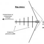
Most of the walkie-talkies from the world's leading manufacturers have a range of about a kilometer, which allows the guards to talk to each other while guarding an object. Sooner or later, every person using a walkie-talkie has a desire to increase the range of its action. There are several ways to make this wish come true. For example, if you want to increase the range of your walkie-talkie, replace your regular helical antenna with a special four-wave pin that can be bought in almost every market.
You can also use a long piece of coaxial cable as an antenna, which can significantly amplify the signal. Then adjust the frequency of the radio so that it sends the signal as far as possible.
The range of the antenna also depends on the power of the output path. Choose the optimal frequencies for signal transmission, keeping in mind that closer to the edges of the operating range, many characteristics of a walkie-talkie for truckers, such as sensitivity and power, deteriorate significantly. That is why, as standard, the antenna is tuned to the middle of the frequency range. That is, if your walkie-talkie transmits a signal in the range from 136-174 MHz, then it will show the greatest range at a frequency of 155 MHz.
Use only well-charged batteries as the power output depends on the power supply. Therefore, if you are going to use the radio for a long time, always carry a spare battery with you. Also, if it is necessary to increase the signal transmission range of your midland radio for a communication session, if possible, use hills on the ground.
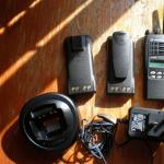
A well-functioning walkie-talkie will allow you to keep in touch with your work colleague and, in case of an unforeseen situation, quickly come to his aid. At the moment, the most popular radio manufacturers are Midland and Motorola. Each of these companies provides the widest range of digital and electronic products from walkie-talkies to multifunctional radios.
To obtain permission to use a radio station operating in the so-called civilian band, no special license is required. Therefore, these types of devices, if necessary, can be improved by improving the quality of communication and expanding the number of functions. If you want to increase the power of your radio, you will need a signal booster.

Receiving and sending radio signals require certain technical tools. If you do not aim at something extremely complex, then you can stop your attention on the CB antenna. With your own hands to do it at the same time, it provides good opportunities for work.
How it all began?
What is CB? This designation is used as an abbreviation for the English phrase "civilian range". It is adopted to refer to available and license-free shortwave radio communications occupying the 27 MHz band. Depending on the country, the rules for its use may regulate the operation to a minimum or none at all. Radio communication equipment can be portable, mobile or stationary. From professional stations (and a large number of amateur ones), they differ in price and the number of available functions. In the simplest versions of this range, you can only receive and transmit audio information over relatively short distances over rough and wooded areas. You can work on eliminating natural disturbances or pay attention to increasing the covered distance. But let's not rush just yet.
Where do they apply?
CB radios have a fairly wide application. They are fairly reliable and affordable means of communication that allow the store to interact with a warehouse, trucks, and so on. CB radios are also used on small fleets - boats and yachts. At the same time, the range of work on the water increases significantly due to the fact that there are no serious obstacles.
The greatest use of the CB range was found as representatives of mobile communications. An example is the devices installed in cars. Portable devices are a little more difficult. The fact is that the CB range has a wavelength of 11 meters. And the ideal antenna for it should be about 2.7 m in size. On portable devices, they have to be shortened by 10-20 times. As a result - a rather large weight, low efficiency when transmitting data to a compact antenna and low efficiency of amplitude noise reduction. But due to the rather significant CB wavelength, the antenna can work even in the presence of significant obstacles. It is well suited for rough terrain and forests.
Helpful information
The CB radio station allows you to contact the police, ambulance, fire brigade and emergency services thanks to special dispatchers. It should be noted that this possibility is not always available. Channel 9C has been allocated for this purpose. But, alas, in practice this can only be found in Moscow and St. Petersburg. In the rest of the territory, it is better to use channel 15C, through which you can establish communication with drivers on the tracks. Additionally, on 19C you can come across amateur radio operators. All these people can be contacted with a call for help. The main thing is that there would be enough power to send and receive a response signal. And now let's consider how to make an antenna with your own hands.
Theoretical training

So, for our homemade work, a number of requirements are put forward:
- It should at least partially provide protection against atmospheric and industrial interference.
- It is necessary to take care of the "ground" for the normal reception of signals.
- To transmit data to an antenna, it must be tuned.
If we talk about the design, then there are two main options: horizontal and vertical execution. Each of them has its own characteristics. To find the optimal solution, the antenna is often placed at a 45 degree position. Vertical execution is considered more difficult, but also better. It requires higher resistance than horizontal. In addition, the latter option is more dependent on the distance to the ground - the farther it is, the higher the resistance. In order to meet different design requirements, several possible designs will be considered. If desired, without much complicating everything, they can be improved. So, how to make an antenna with your own hands?
Very simple option
We will make from improvised materials. Purchased - only UNF connectors and RG-58 cable. The cloth of the antenna will be equal to the wavelength. Adjusting to resonance, it can be shortened and made a little longer. If the transmitter is coaxial, then the power must be balanced. The easiest way is to use a low frequency ferrite (from 400 to 2000 HN). When creating with your own hands, a transformer from a computer power supply can act as its role. It should be noted that standard yellow rings are not suitable, so two turns of cable must be wound around the core. And this is where one question comes into play. Namely - which cable for the antenna to choose? Let's say that we need an optimal solution in the price/quality coordinate system. In this case, you can pay attention to the usual piece of wire ShVVP 2X0.75. It is divided into two conductors which are soldered together. The total length should be eleven meters. At the same time, the observance of equality of the parties is not a critical point. As an insulator, you can use a plastic ring - for example, from a baby rattle.
dipole radio

With your own hands, a CB antenna of this type can be easily made. After all, the dipole is considered very simple to learn and implement. You can create a device suitable for long-term maintenance-free operation. In addition, it can work well in not the most favorable conditions. What is a dipole? In fact, this is the simplest and at the same time the most common antenna, presented in the form of a symmetrical vibrator. The simplest implementation is a straight conductor, the length of which is equal to half a wave, powered by high-frequency currents from a generator. In simple words, they take two identical pieces of wire, stretch them sequentially in space. A cable is connected in the center of this structure, from which the signal is transmitted from the dipole to the transceiver and back.
Do-it-yourself CB antenna can be made vertically or horizontally. The first option is more suitable for establishing local communications, and the second for long-distance communications. If the dipole is at an angle, then both possibilities are available.
Designing a dipole

Before we start doing something, we need to calculate what we need. It should be understood that the geometric length of the dipole will be slightly less than that calculated by the formula. Why? This is due to the process of occurrence of capacitive current at the ends of the antenna, which is equivalent to an increase in its length. The exact length of the dipole (which takes into account the velocity factor) can be calculated using formulas that will not be given here, since technological tools in the form of simulators can be used to achieve this goal. MMANA was used as such. So, it turned out that the top point should be at a height of three meters, the center - 2.5, and the bottom - 2 m. The length of the arms is 2.57 m, the wire chosen to create the antenna has a diameter of 2 millimeters. This design has a resistance of approximately 75 ohms. This is equivalent to SWR=1.5. To feed the antenna, you can choose a balancing device. It is essentially a balun transformer. Why exactly, and not, say, through a coaxial cable? The fact is that the dipole is a symmetrical antenna. And she will not be able to eat from the cable, because it is an unbalanced line.
Assembling the antenna

So, to create we need:
- Plumbing plastic coupling. Suitable with a diameter of 50-55 cm.
- Connector SO-239.
- Plumbing plugs, commensurate with the previously selected coupling.
- Screw-ring in the amount of three pieces.
- Three nuts and six washers.
In the coupling, we make a plug for fastening in 6 millimeters and for a 16 mm connector. Then you can connect or assemble the balun. We'll pretend we don't want to buy. Therefore, we take a ferrite ring, which has a permeability of 600, a piece of wire with a cross section of 0.5-1 mm. We fold the wire in three and begin to wind it around the ring. After a full-fledged CB antenna coil is ready, the winding is fixed with an insulating tape or clamps. We mount the balun into the workpiece, after which we solder the connector. The structure is almost ready. It remains to measure the required number of wires for the best antenna in order to fix them on the workpiece. Thickness does not play a role here. As an example - you can take three meters of 1.5 mm. By the way, although the program calculated that 2.57 is optimal, it is better to take a little with a margin. Therefore, three meters. We solder everything - and our antenna is ready.
Setup and some specific points
Since the dipole is a symmetrical antenna, the length of the arms must be the same. When creating the first devices, it is desirable not to deviate from the specified parameters. And it’s better to take a little more than the calculations indicate, because you can always cut off, while welding is much more difficult. The result is a fairly simple and versatile antenna. You can pick it up in an hour. Pretty good considering the satisfactory result.
For auto

A modern vehicle necessarily has a radio or even something more. Navigation, television and radio communications - this is not a complete list. But very often you have to buy something you want on your own. Or do. For example, do-it-yourself car antenna for the possibility of radio communication. How to implement it? Ordinary antennas will not work. Why? The fact is that vehicles often move during communication sessions. And traditional antennas in this case will have a certain "dead" reception area. Even if you drive in such a way as to prevent this, communication breaks still occur when maneuvering.
Summing up, we can understand that a do-it-yourself car antenna must meet the following requirements:
- Have a high efficiency (after all, CB is needed not only to listen, but also to transmit information).
- Ensure reliable operation at the selected frequency.
- Fit in the salon.
- Do not raise questions from traffic cops regarding the refinement of the hulls.
Specifics of car antennas

The quarter-wave transmitter can be discarded at once - it is too big. Our CB radio station in this case will not satisfy with its size. But if the machine has a frame structure, then you can take advantage of its advantages. In order to tune the antenna to resonance with the desired frequency, a capacitor is used. But what about the length? One of the most popular solutions is the design of the antenna in the form of a spiral. Another, not inferior in popularity, method is to make the antenna in the form of a trapezoid. In this case, it is recommended that the length of the CB antenna be as follows: top edge - 56.5 cm, bottom base - 66.5 cm, sides - 22.5 cm + 45 cm for connection. As you can see, by making not very significant changes to the design, we were able to get the same thing that was needed before. That's just a trapezoidal antenna fits easily into a car. In general, there is a very large space for the flight of thought.
Conclusion
That's all, the main material has been successfully considered. It is not difficult to turn antenna drawings into a finished device with your own hands. But if there is no experience, then there may be certain problems with this. As they say, the road will be mastered by the walking one. If the first time you create a CB antenna does not work, then you should not be disappointed. Perhaps something was poorly soldered or not executed well enough, they forgot to connect the power supply or something else. In addition, even if everything is done correctly, it cannot be ruled out that a certain element burned out or was produced with a marriage.
Avoid making antennas on walkie-talkies for cars with your own hands for the simple reason that then the equipment is difficult to set up. The standard devices at the base contain a nut-like assembly that allows the driver to tune the device to the wave being used. For manual models, the situation is different. An antenna for a walkie-talkie with your own hands can be made, however, there will be problems for large enterprises buying a frequency. The State Committee monitors the sold goods so that consumers avoid mutual interference. Railroads do not intersect with shipyards. Sometimes industrialists need communication, everyone will start to improve equipment, we will find a situation: subscribers will hear each other. Working in different companies. Ask the SCRF: they will give recommendations, perhaps it will be enough to demonstrate to specialists in action the refinement to assess the impact on neighboring communication domains.
Communication and radio antennas
It has been repeatedly said: in everyday life, linear, circular polarization is more often used, the latter - mainly on satellites. Radio is no exception. Television took away horizontal polarization, leaving vertical broadcasting ... walkie-talkies. Logically. When we hold the radio, the antenna is vertical. The signal reflected by the terrain is visible, rotated by a fixed angle. Thanks to the effect, the dull military man demonstrates a "violation" of the laws of physics ... Ideal reception is carried out by a vertically standing antenna. Do not believe - do the opposite!
Those who read reviews about homemade antennas will be amazed, but not surprised. Again unbalanced quarter-wave vibrators made from a piece of standard coaxial cable. Polarization, frequencies, why something should change. Once they said: a television antenna made of cable can be placed vertically, catch the radio, find one on the right wave ...
Native radio antenna. Inside the knob there is a copper spiral, the tip of which is attached near the top. For some walkie-talkies, you can simply get to the curls, for others, the problem is unsolvable. Why spiral?
According to the course of the electrodynamics of radio wave propagation, the antenna radiates in the direction of the axis, the wave will be polarized in a circle, according to the direction of the curl. Only if the length of the coil is close to the value of the wavelength. The context under consideration suggests a figure of half a meter or more, forget about proximity.
An idea of the radiation pattern is given by the MMANA program. Well-wishers kindly put the radio antenna (145 MHz) in there, avoiding changing the parameters, looked at the field (opening the application):
- In vertical polarization, an even circle came out in azimuth. It is clear that the human body will distort the diagram! Indeed, the spiral radiates vertical polarization almost exactly. The level is - 3 dBi.
- Horizontal polarization is shaped like a figure eight, the level is much lower. If you hold a walkie-talkie with a spiral antenna horizontally, the reception will worsen, it will not reach zero.
A semicircle is formed in elevation with horizontal polarization, and a dip along the axis with vertical polarization. The useful upward signal is not emitted. Let the person with the walkie-talkie climb the tree. And both hold the devices vertically, the reception will be due only to the horizontal component, as well as the reflected signal. These are the antennas used by walkie-talkies ... It is not surprising that amateurs are gnawed by the desire to change the design. Therefore, spirals are used.

In fact - and on the MMA file - the antenna consists of a spiral, a cap plays a significant role. The idea is clear. In real conditions, communication must be carried out in all directions, a quarter-wave vibrator is unable to meet the specified requirements. Why a quarter. The half-wave vibrator is longer. Dimensions matter. Spirals began to twist not from a full life. Just a long antenna for a walkie-talkie is too great a luxury. A pocket will be pierced, you will be tormented to hold it with your hand, windy weather will vomit. You have to make sacrifices. Recall that in terms of vertical polarization, the radiation pattern demonstrates the similarity of a torus, typically. The horizontal one adds something like a dumbbell (a rough approximation), which forms the missing corners, sections of space. For reception and transmission, the radiation pattern is the same.
We will design walkie-talkies, removing unusual properties of reception in all directions. The energy will rush in the direction of the torus. The broadcast distance will increase. If we re-equip both walkie-talkies, we get an additional gain at the cost of losing the final reception (transmission) from top to bottom. We remind you that the radiation patterns for receiving and transmitting are the same (identical).

Increase the range of the radio station by redoing the antenna
The conclusion is obvious: we want to increase the range - we saw the radiation pattern of the factory antenna - we need to direct the power to vertical polarization, to the torus. How to do it is clear, but one question looms on the horizon - the impedance of the radio antenna. Do you know the meaning? They talked about how to measure! If the feedline length is a multiple of half a wavelength, the antenna impedance is passed to the output unchanged. The effect is used for measurement.
Various devices are used (RF generator). For those who are thinking about taking this, let's say: the local oscillator of the TV is capable of delivering a similar frequency, it's another matter to set it up. Let's talk separately. You will need a high-frequency voltmeter, the usual one is unsuitable for measurement purposes. The device is measured by the voltage of the RF generator in suspension, the scale is calibrated to show 100%. Assemble a circuit connected in series:
- antennas;
- variable resistor.

Connect the generator to the circuit, measure the voltage of the resistor. Turn the adjustment until the arrow starts to show 50%. The resistance of the variable resistor becomes equal to the characteristic impedance of the antenna. It is necessary to take a non-inductive resistance (which does not have its own inductance). A homemade radio antenna, if possible, should repeat the electrical parameters of the factory one. Wave resistance is taken close to the original. The measurement process is clear to readers.
The choice of constructor is small: two global families. Cables with impedance 50, 75 ohms. The first is used by communications, the second - by television. The portable radio antenna is made from the one that is closer to the nominal value of the measured value. A quarter-wave vibrator (devoid of a spiral) has a resistance of 35 ohms. It is difficult to predict the parameters of a purchased antenna. It is easier for practitioners to make two antennas for a walkie-talkie using a cable of a different grade. Then each test on the ground, assessing the nature of the changes.
Making a radio antenna
Let us briefly recall the process of manufacturing an antenna for a walkie-talkie. Considered digital TV, WiFi, 3G. The audience of the VashTechnik portal knows how to make an antenna for a walkie-talkie. Feel free to copy techniques. First you need to know the frequency. More precisely, better. Walkie-talkies have several channels, the frequencies are registered in the passport. Select a channel by specifying the dimensions of the antenna.
Let the frequency be 435 MHz. We find the wavelength according to the school formula, dividing the speed of light by the specified value: 299792458 / 435000000 = 689 mm. To make a quarter-wave vibrator, you need to divide the number by another 4, we get - 172.25. The length of the antenna for the walkie-talkie will be 17 cm. Try to withstand millimeters more accurately. The screen cannot be cleaned. It will be a receiving surface, the band will increase. Hands itch - peel off, like a peel, braid, leave the dielectric around the main core.
The old antenna is soldered, a clamp is ready for the new one. It remains to close up in place, enjoy the connection. The antenna for the walkie-talkie is made by hand. By the way, if there is no desire to remove the screen, solder together with the core in one bundle when mounting on a microcircuit. You consider the expansion of the range to be superfluous - it is better to remove the screen. The first and second options are endowed with advantages, a solid cable is stronger. Better to leave it as is. The radio antenna will last longer. Take care to glue on a nice cap-tip so that the copper stops oxidizing. We say goodbye until next time.
Copy factory designs. Walkie-talkies of enterprises break down. Adapters remain, devices are thrown away. An invaluable chance for a radio amateur to prove himself. The antenna is covered with rubber, easily peeled off. Or use an accessory of a broken product. The copying process is not directly prohibited, except for products protected by patents. The case concerns the industrial production of products for the purpose of marketing, obtaining a fixed profit through the implementation of these actions.
This circuit of a shortwave radio station contains only three transistors. The easiest walkie-talkie to repeat for beginner radio amateurs. The design was taken from an old magazine, but it has not lost a bit of its relevance. The only thing that is outdated is the radio components that need to be replaced with modern analogues, as a result, the characteristics of the radio intercom will improve.
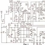
Radio station diagram
The scheme is simple, especially if you understand its work. I suggest you immediately visually divide it into the left side with one transistor and the right side with two transistors. Transmitter and receiver are assembled on transistor VT1 at the same time. When the switch closes the "1" contacts, the radio is in receive mode and this transistor operates in supergenerative detector mode. And when the contacts close in mode "2" - this is a transmission and the transistor works as a master oscillator. With this, I think it's clear. A simple low-frequency amplifier is assembled on the transistor VT2, VT3, which, depending on the position of the switch, either amplifies the signal from the microphone and transmits it to the transmitter, or amplifies the signal of the supergenerative detector and transmits it to the loudspeaker. By the way, the loudspeaker and microphone are the same element - a high-resistance DEM telephone capsule.Radio parts
Coil L1 is wound on a frame with a diameter of 8 mm with a ferrite core turn to turn and has 9 turns of PEL wire with a diameter of 0.5 mm. Coil L2 is wound on top of coil L1 and has 3 turns of the same wire. Coil L3 has a diameter of 5 mm and contains 60 turns of PEL wire with a diameter of 0.5 mm. As a choke L4, you can use the primary winding of the output transformer of the transistor receiver.Antenna design

The antenna was made by me from a thick aluminum wire, with a piece of insulation, on top of which the L3 coil was wound.
My modernization
I made such a walkie-talkie back in school, but then I already changed all the transistors to more modern ones and with a high gain. For example, I replaced VT1, VT2 with KT361, and VT3 with KT315.Now, of course, I would change the polarity of the power supply and the polarity of the capacitors, replace all transistors from the n-p-n structure to p-n-p, and p-n-p to n-p-n. Well, I would install modern transistors. There are no special requirements for transistors, so absolutely any will do.
The author of the scheme says that the radius of action of the same type of radium in open areas is 100-200 meters. I overclocked such walkie-talkies up to 500 meters, for this I used modern transistors, increased the antenna to 900 mm, plus increased the generator current by replacing the 100 Ohm resistor with 50 Ohm. Someone will say that everything is due to the increase in the antenna, with which I disagree and say that with the “native” antenna I was able to communicate at 300 meters.
Setting
If you assembled the radio correctly and from serviceable parts, then the whole setup will come down to setting the L1 coil to a frequency of 27 MHz. This can be done with a subscript core, or a capacitor in the circuit.Walkie-talkies are widely used in various spheres of life. So, they can serve as a baby monitor in the event that there is not enough money for a special device for communicating with a child.
You can use the walkie-talkie for security guards or tourism enthusiasts to communicate with companions, but it is not at all necessary to set aside a tidy sum for the purchase of this equipment, because you can create a walkie-talkie with your own hands at home. In addition to getting the final product, this is a very interesting and fun activity.

So, what do you need to make a walkie-talkie?
To create a walkie-talkie, you will need the following items:
- 4 MP-42 transistors and 3 P416B transistors;
- Resistors. They will need a lot: two pcs. 3K, 160K, 4.7K, one each - 22K, 36K, 100K, 120K, 270K, and six pcs. 6.8 K;
- Capacitors: two 10 MK 10 V, 3300, 1000, 100, 6, 5-20, 22, 10 and one 5 MK 10 V - 4; 0, 0, 47 MK.
- Telescopic antenna;
- Microphones and speakers;
- Textolite boards - 2 pcs.
- soldering iron;
- Socket;
- Wire cutters.

Almost all of the above is included in a special kit for radio amateurs JC986A. The further algorithm will be based on this set.

It is worth considering that creating your own walkie-talkie requires skills in working with a soldering iron and knowledge of how to determine the values \u200b\u200bof the elements.


Algorithm for creating a 50 MHz radio
If you purchased a ready-made kit for creating a walkie-talkie with your own hands, you will need the following diagram. The names of the elements must be indicated on your board and the diagram attached to the device for making a simple walkie-talkie.

First, start installing resistors, form the electrodes of this element. Using a soldering iron, the resistor must be soldered to the board, and the protruding electrodes should be cut with wire cutters. Carefully and carefully install all the components, based on the drawn outline on the board.

Take care of soldering the extension coil L 1, and then the capacitors. The next step is to solder the electrolytic capacitors. Since they have a certain polarity, it is necessary to correctly fit the negative electrode into the board.

Using a soldering iron, attach the contour coil T 1 and the body of the switching element S 1. Proceed with soldering the transistors, relying on the circuit drawn on the board. You need to solder the cut off parts of the electrodes left from step 1 to the board. Do this so that jumpers J 1 are formed.

Now you can check the quality of the work done. If necessary, wipe the board with an alcohol solution, and later install an on and off button. Attach the finished board to the case using self-tapping screws.

Now you can install one of the main elements of the radio - the antenna. A small plastic cap should be located on top of it, on the other hand, you need to solder the conductor that will articulate the antenna with the board. Attach switch S 2 to the board using the remaining pieces of conductors and check its functionality.

Place the terminals in the battery section. Now you need to solder the conductors responsible for the speaker and the power supply system. If you have no doubt that you did everything right, connect a battery to the mechanism and check it. The finished device should make hissing sounds.

Assemble the second walkie-talkie in the same way as the first. In order for the devices to work at the same purity, remove one board from the fastener. We hope that this detailed instruction for creating a walkie-talkie with your own hands helped you deal with the creation of this mechanism.

Debugging a homemade radio
Even if you carefully followed the indicated algorithm, the technique may not work properly. In order to adjust the operation of the mechanism, use a variable resistor and wait for the maximum volume of the hiss of the radio.

Use the tuning core to change the level of inductance until the signal improves. After that, do not forget to return the original resistor and adjust its resistance.

If your voice emitted by the second walkie-talkie is heavily distorted, pick up other resistors and start creating a wavemeter, the diagram of which you can find on the Internet along with photos of homemade walkie-talkies. By the way, you need to check the quality of communication at a distance of 5, then 10 and 20 meters, it is better to do this in open space.


We described a step-by-step algorithm of how you can make a walkie-talkie with your own hands. It should help you create your own mechanism to keep in touch with family or friends while hiking, hiking, fishing or with a child.

Remember to take precautions when working with this technique to avoid the risk of injury such as burns or electric shock.

DIY radio photo


