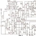
(the simplest walkie-talkie) is shown in Figure 1.
The radio intercom contains only three transistors. In the receive mode, a supergenerative detector is implemented on VT1, and in the transmit mode, the cascade on this serves as a master oscillator that emits a carrier frequency to the antenna.
On transistors VT2 VT3 in the receive mode serves as an amplifier for the received signal, and in the transmission mode it switches as an amplifier. DEM capsule, used as a microphone during transmission.
Details
Coil L1 is wound turn to turn on a frame with a diameter of 8 mm with an SCR core and has 9 turns of PEL wire with a diameter of 0.5 mm. Coil L2 is wound on top of it and has 3 turns of the same wire. Its diameter is 5 mm, it contains 60 turns of PEL wire with a diameter of 0.5 mm. As a choke L4, you can use the primary winding of the output transformer of a pocket transistor receiver.
The radio station is intended for work in the car, the boat or stationary conditions. It requires a source of direct voltage of 12 - 15 V with at least 1 A. The communication range with a similar radio station is about 2 - 5 km in the city, up to 15 km on the highway and up to 30 km when operating in stationary mode on a full-size antenna located on mast. The radio station works with an antenna having a wave impedance of 75 ohms.
SPECIFICATIONS OF VEHICLE MW RADIO
- Working range .................................................................. ......................... 27 MHz.
- Transmitter output power at voltage
- Frequency modulation with deviation ....................................................... .......2.5 kHz.
- Consumption current for transmission, not more than .............................................. ......0.6 A.
- Current consumption on reception, not more than .............................................. ......0.015 A.
- The sensitivity of the receiver with a signal-to-noise ratio is not worse than .............. 1 μV.
- Adjacent channel selectivity with a detuning of ±10 kHz is not worse than ....... 36dB.
12V power supply on a load of 75 Ohm .............................................. ...................3 W.
The scheme of a pocket radio station (see Fig. 1) does not contain scarce elements, it is easy to configure and easy to build. However, for all its simplicity, it has good characteristics. Receiver sensitivity - no worse than 10 μV, transmitter power - 250 mW, operating frequency - 27.14 MHz, communication radius in open areas - up to 1 km.

The receiver of a pocket radio station, made on transistors, is a super-regenerative (VT2) and aperiodic (VT1). A useful signal is allocated on the resistor R5, however, it is much smaller with the frequency of suppression of the super-regenerator. To suppress unnecessary noise and highlight the useful signal, the receiver has a C12R7C13L7C14 filter. From it, the signal is fed to the resistor R13, which is the volume control, and then to the audio frequency, made on transistors VT8, VT10, VT11.]
The pocket radio transmitter is assembled on five VT3-VT7 transistors and is a push-pull self-oscillator, the signal of which is fed to the antenna through the L2 communication coil and the L1C3 matching circuit. Parallel connection of VT3, VT6 and VT4, VT7 allows you to increase the power delivered to the transmitter antenna.
The use of portable radio microphones is usually associated with a power supply problem, due to the need to regularly recharge batteries or change batteries. However, autonomous power is not always necessary. The proposed radio microphone is designed to be powered by 220 V, but differs from conventional circuits containing a mains transformer or a quenching capacitor. Due to the low current consumption, it turned out to be possible to use quenching resistors, which have much smaller dimensions. The principle of a "network" radio microphone is shown in the figure below:
 network radio microphone" alt=" radio microphone diagram">!}
The full-wave rectifier is assembled on diodes VD2 and VD3, the voltage is supplied to it from through the quenching resistors R4, R5, and VD1 (about 8 V) is stabilized from the rectifier output.
With cascode connection
As a rule, all schemes of portable radio stations published on the pages of "RL" are designed for a city dweller, for his ability to get scarce elements, rare microcircuits. And for us, the villagers, it is very difficult to repeat a different design. Meanwhile, personal radio communication is relevant precisely in villages and villages, where even now one telephone set is sometimes installed for the entire district.
I myself am a rural resident, and therefore, when developing this design, I tried to take into account our problems with the availability of the element base.
The radio station consists of two parts: a transmitter and a receiver. The transmitter is assembled on a 1.5 mm thick fiberglass board measuring 100 mm x 45 m. The receiver is 60 x 45 mm. Why are there two fees? The fact is that these are two independent designs that can be improved independently of each other. There is one more detail. This design very easily turns into a radiotelephone, since the receiver and transmitter can work simultaneously if they are detuned relative to each other.
The transmitter circuit and coil data are shown in Fig. 1.
The transmitter is assembled on five transistors. Two transistors - in the modulator. Three - in the transmitting part. Transistors are not critical in selection. Any silicon can be used in the modulator: KT315, KT503, KT306, i.e. usually those that can be soldered from old receivers, tape recorders.
The master oscillator also has a wide selection of transistors. KT315, KT306, KT316, KT368 work well here. Quartz - at 27 MHz. In the second stage, KT603, KT604, KT605 work well.
In the power amplifier, you can use transistors such as KT610, KT606, KT907, KT922.
All transmitter coils are wound on IF circuits from industrial radio stations or radio receivers. Coils - with screens and cores. They are very easy to set up, you just need to have a simple wavemeter.
The setting begins with the master oscillator - according to the maximum deviation of the wavemeter needle. The second and third stages are set up in the same way.
The transmitter works confidently on a 7D-0.125D battery, which is also important for a rural radio amateur.
The modulator uses a DEMSh-1 capsule instead of a microphone.
The K174UN4V microcircuit was used as an amplifier, which is sufficient for loud-speaking radio communication. Its setting is available even to a beginner.
Any RF transistor, both silicon and germanium, can work in the first stage of the receiver. for example, KT306, KT368, KT316, KT315.
The second stage is the regenerator. There are problems here. In these stages, only germanium transistors usually behave well, so GT311 Zh, A, C, B work here. The use of silicon transistors gives unstable results.
A properly assembled receiver begins to act immediately, and the indicator of its operation is noise.
They tune it to the transmitter from their own design for the disappearance of noise. The final tuning is carried out already at the maximum distance of the two radio stations from each other.
The antenna used is spiral, the design of which was given in "RL" N5 / 92, p. 14.
I have collected two radio stations that have been serving faithfully for three years. Confident range - 2.5 km - 3 km.
When working in stationary conditions and powered by 12 volts, as well as when using an external whip antenna, the range reaches 10 km.
I do not give printed wiring, because due to the wide range of parts of this radio station, the dimensions of the boards can be arbitrary.
| This is where your opinion matters. - put your rating (rated - 4 times) |
Are you tired of paying for mobile communications all the time? Do you want to upgrade to a free plan? Or do you want to have a constant, free connection with your boys in the area? Then this walkie-talkie diagram, which you can assemble with your own hands, is for you.
To make one radio you need:
- Transistors: P416B (3pcs) and MP42 (4pcs);
- Resistors: 3K (2pcs), 160K(2pcs), 4.7K (2pcs), 22K, 36K, 100K, 120K, 270K, 6.8K (6pcs);
- Capacitors: 10MK*10V (2pcs), 3300MK (2pcs), 1000MK (2pcs), 100MK (2pcs), 6MK (2pcs), 5-20MK (2pcs), 22MK, 10MK, 0.047MK, 5MK*10V (4pcs);
- Antenna;
- Microphone, speaker;
- Switch, switch;
- DC source;
- Textolite boards (2pcs);
- wires;
- Wire with a diameter of 0.1 mm. and 0.5 mm.
Scheme of a simple homemade walkie-talkie:
How to make a walkie-talkie with your own hands
The common antenna for receiving and sending a signal is A1.
Power switch - SA1.
A switch that connects a homemade radio station with a current source, while sending a signal to the transmitter and the receiver upon receipt - SA2.

Number of turns:
Coils L1 and L5 - 10 turns.
Coil L2 - 4 turns and it is located between the halves of the winding of the coil L3 containing 8 turns and having a wire outlet in the middle.
Coils L4 and L6 - 200 turns, 0.1 mm wire around the MLE-0.5 resistor with min. resistance 1 Mohm.

Well, the coils for the walkie-talkie are ready.
If you have not yet lost the desire to make handheld radios, then for sure you understand at least something in electronics and it means that it will not be difficult for you to place the parts on two boards (one of which is with a master oscillator, and the other with a receiver and bass amplifier) on one side and connect them with an insulated wire ( diameter 0.2-0.3mm) on the other. Then connect with PVC-insulated stranded wire to the battery.
Printed wiring can be done if there is a foil getinaks, and for the frame of a home-made walkie-talkie, centimeter wire cuts driven into holes with a diameter of 1 mm are suitable.

The windings of the coils and chokes should be mutually perpendicular, and the C15 knob should be located on the front panel of the radio. The generator must be separated by a tin screen from other parts.
Setting up and debugging the radio
They start debugging by improving the reception quality, for this it is necessary to replace R10 with a variable one with a resistance of 33-47 kOhm and wait for the maximum noise volume. Next, with a tuning core, we change the inductance L5, achieving the highest quality signal. After that, we return the old resistor.
RADIO SCHEME
In some cases, it is not possible to use a mobile phone, and, for example, communication is needed all the time. For these purposes, it is proposed to assemble this radio circuit. The receiving part of the device is made according to the classical scheme on 174XA34. The bass amplifier can be made on transistors or so on. I used a 174XA10 chip for it, or rather its part with ULF.
The transmitter can be taken from our article: or run on the MC2833 chip, the diagram is also on the site.Let's look inside radio diagrams:

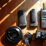
The case is made of sheet millimetric aluminum and glued with black self-adhesive. Small speaker with 8 ohm coil resistance, microphone from radiotelephone or tape recorder. Red LED indicates transmission, green LED indicates power on. The 7 V source is assembled from two spent batteries from mobile phones. The antenna is wound with a PEL 0.3 wire on a TV cable without a braid and a central core. The receiver has a frequency control within 105 - 110 MHz. This is done in order to be able to listen to FM.

This is what the finished kit looks like walkie-talkie:
How to make a radio
If you are tired of endless bills for mobile communications and want to switch to the “Free” tariff, if you dream of making your own radio station for the boys in the area, or simply want to maintain the anonymity of negotiations at a distance of up to one and a half kilometers, then the diagram below of a simple home-made walkie-talkie is yours hands just for you.
How to make a homemade radio?
Making a simple walkie-talkie with your own hands is much more difficult than buying a ready-made version in a store, but who knows where an extreme situation will find you, all of a sudden it will be a transport disaster that, by a lucky chance, transports:
3 P416B transistors, 4 MP42 transistors
Resistors for 3K, 160K and 4.7K 2 each, for 22K, 36K, 100K, 120K and 270K 1 each and as many as 6 resistors of the 6.8K type
Capacitors of type 10MK * 10V, 3300, 1000, 100, 6, 5-20, 2 each, 22, 10 and 0.047MK, 1 each, and as many as 4 capacitors of type 5MK * 10V
antenna, microphone, speaker, switch, switch, direct current source, 2 PCB boards, connecting wires and wire with a diameter of 0.5 and 0.1 mm
multiplied by the number of homemade walkie-talkies that you are going to make with your own hands.
Scheme of a simple homemade walkie-talkie:
where, A1 is one common antenna for sending and receiving a signal, SA1 is the power switch, and switch SA2 will connect the homemade radio to a power source: while sending a signal to the transmitter, and respectively to the receiver during receiving.

The following figure clearly shows the winding diagram of the coils, which will be based on plexiglass, polystyrene or, in extreme cases, cardboard cylinders with a diameter of 0.8 cm and a height of 2 cm, and as a winding - 1 layer of copper wire with a diameter of 0.5 mm, which is called turn to turn . Coils L5 and L1 of your simple homemade walkie-talkie with your own hands should have ten turns, coil L2 should consist of four turns and is located between the halves of the L3 winding, which consists of eight turns and has a wire outlet in the middle. For those who do not understand simple radio circuits with their own hands, the L3 and L2 coils are wound on the same basis.
L4 and L6 are a 200 turn winding of 0.1 mm wire around the body of MLT-0.5 type resistors with a minimum resistance of 1 MΩ.

If you have read up to these lines, then you probably understand at least something in electrical engineering, and therefore place the parts on textolite boards (one of them will be with a master oscillator, and the other with a low-frequency amplifier and receiver) on one side and connecting them on the other side with an insulated wire with a diameter of 0.2-0.3 mm, it should not be difficult for you, however, as well as connecting the batteries with a stranded wire insulated with vinyl chloride. You can make a printed circuit with a foil-coated getinaks, and the frame of your simple home-made walkie-talkie can be made with centimeter pieces of copper wire driven into holes with a diameter of one millimeter.

It remains to make sure that the windings of the chokes and coils are mutually perpendicular, the handle of the C15 capacitor is located on the front panel of the radio station, and the master oscillator is separated from other parts of your simple homemade walkie-talkie with your own hands by a tin screen, which in turn is connected to the "+" power supply.
The absence of a microphone will successfully correct the presence of a pair of high-impedance headphones, and instead of a telescopic antenna from a radio receiver, you can use a meter-long brass tube with a diameter of 0.5 cm.
Setting up and debugging a homemade radio
Even if you regularly attended all the classes of the circle of young radio amateurs, it is not a fact that your simple walkie-talkie with your own hands will immediately work as it should.
Debugging a homemade walkie-talkie begins with improving the quality of signal reception, for which change R10 to a variable resistor of 33-47 kOhm and wait until the noise becomes as loud as possible. Now change the level of inductance L5 with a tuning core, achieving a better signal quality, and finally change the variable resistor back to a constant one with the desired resistance.
If the timbre of your voice is greatly distorted during signal transmission, select resistors R1 and R3 more carefully, and to debug the generator and antenna, assemble a wavemeter, the electronic circuit of which is shown below. The basis for the coil L of ten turns of 1.2 mm wire will be a frame with a diameter of 2.2 cm, where the third turn from the bottom is the tap. Capacitor C1 needs to be made trimmer, with an air dielectric, and its handle should be placed opposite the current frequency of the signal transmitter of your homemade walkie-talkie, making sure that its L3 coil is next to the L wavemeter coil, thus making it a kind of indicator. Now, trying capacitors of different capacities instead of C9, you need to achieve the maximum deviation of the arrow on the wavemeter division scale, and, bringing the latter directly to the antenna itself and rotating the tuning core L1, debug the antenna in resonance with the tuning frequency of the L3C8C9 circuit until the arrow on the wavemeter scale shows the maximum deviation.
How to make a radio station with your own hands
You can download free schemes for making many types of receivers and transmitters yourself at home, ranging from a home-made radio station to radios and walkie-talkies of various types.
