Home ventilation plays a very important role, maintaining the microclimate necessary for a person. The health of those living in the house depends on how correctly it is designed and executed. However, it is not only the project that matters. It is very important to correctly calculate the parameters of the air lines. Today we will talk about such work as calculating the area of \u200b\u200bair ducts and fittings, which is necessary for the correct air exchange of an apartment or a private house. We will learn how to calculate the air velocity in mines, what affects this parameter, and we will also analyze what programs can be used for more accurate calculations.
Read in the article:
Why is the area of air ducts and fittings calculated?
The correct design of ventilation systems is only half the battle. If you make a mistake in calculating the quadrature of the air ducts, then you can get the opposite effect - there is an ideal plan, but there is no outflow or inflow of air. Such miscalculations can lead to the fact that there will be increased humidity in the premises, which will lead to the appearance of fungus, mold and an unpleasant odor.
Very important! If the home master is not confident in his abilities, he is afraid not to cope with the calculations, then it is better to seek engineering help in calculating the air ducts. It is better to pay a professional for the work than to bite your elbows later.

Data required for calculating the parameters of the duct
- sanitary and hygienic standards (SanPiN);
- the number of residents;
- area of premises.
In this case, calculations are carried out both for the entire dwelling as a whole, and for each room in particular. There are various ways to calculate. You can use the formulas that we will definitely consider in today's article, however, the easiest way is to use a special online duct surface area calculator. It already contains all the necessary algorithms and formulas. Another advantage of the program is the absence of a human factor - you don’t have to worry that an error will creep into the calculations.

How to calculate duct area using formulas
In order to correctly perform all the calculations, you must first determine the cross section of the shaped products. They may be:
- in the form of a square or rectangle:
- round (rarely oval).
Consider which formulas are applicable for certain calculations. Let's start with square or rectangular products.

How to calculate the area of a rectangular duct: formulas and decoding of symbols
The formula for the duct area required for a proper ventilation device is quite simple:
S=A×B , where
- S – area, m²;
- BUT – box width, m;
- AT - height, m.
With a round duct, the situation is slightly different.

Calculation of the area of a circular duct: the nuances of calculations
Round ventilation shafts have the best throughput - the air does not encounter any obstacles in its path. In addition, the installation of round parts is much easier than square or rectangular ones. The area is calculated using the formula:
S = π × D 2 / 4 , where:
- S – area, m²;
- π - a constant value equal to 3.14;
- D – diameter, m.

Expert opinion
HVAC design engineer (heating, ventilation and air conditioning) LLC "ASP North-West"
Ask a specialist“The shorter the ventilation ducts, the better the system will perform its task. It should be noted that with an increase in the size of the mines, the air flow rate and the noise produced during the movement of air masses decrease. Calculations of straight sections should be made separately, do not forget about the pressure loss in the network.”

Calculation of shaped parts of air ducts - how it is made and what should be taken into account
Calculating the area of shaped parts of air ducts without a special program is only possible for experienced design engineers. Today, entire departments of various institutes are working on improving calculator programs that can calculate the area of air ducts and fittings up to a millimeter, taking into account the slightest changes in bending angles and other nuances.
On the Internet, you can find many similar programs that can perform calculations with minimal errors. And similar calculators come out almost daily. They allow not only to calculate the necessary parameters, but also to scan all the details of the duct. Many will ask - what is it for? In our age of high technology, such an innovation as a 3D printer has appeared. We send a scan of our ventilation to it from the computer and as a result we get perfectly fitted ventilation ducts with the necessary parameters.

The editors of the site invite the dear reader to use the online calculator for calculating the area of air ducts and fittings. All that is required from the user is to correctly enter the requested parameters in the appropriate fields and click the "Calculate" button. The program will do the rest for you.
How to calculate the cross section of the duct in square meters
An error in the calculation of this parameter of the ventilation system can be fatal. A decrease in the required indicator will inevitably lead to an increase in pressure in the mines, which means that an extraneous hum will appear, which is quite annoying. This means that the calculations must be done carefully, without missing the slightest detail, without rounding the numbers. The calculation of square meters is made according to the formula:
S = L×k/w , where
- S – cross-sectional area, m²;
- L – air consumption, m³/h;
- k is the speed with which the air flow moves, m/s;
- w - calculation coefficient, which is equal to 2.778.

Creating comfortable conditions for staying indoors is impossible without aerodynamic calculation of air ducts. Based on the data obtained, the diameter of the pipe section, the power of the fans, the number and characteristics of the branches are determined. Additionally, the power of the heaters, the parameters of the inlet and outlet openings can be calculated. Depending on the specific purpose of the rooms, the maximum allowable noise level, the frequency of air exchange, the direction and speed of flows in the room are taken into account.
Modern requirements for are prescribed in the Code of Rules SP 60.13330.2012. The normalized parameters of microclimate indicators in rooms for various purposes are given in GOST 30494, SanPiN 2.1.3.2630, SanPiN 2.4.1.1249 and SanPiN 2.1.2.2645. When calculating the indicators of ventilation systems, all provisions must be taken into account without fail.
Aerodynamic calculation of air ducts - algorithm of actions
The work includes several successive stages, each of which solves local problems. The data obtained is formatted in the form of tables, on the basis of which schematic diagrams and graphs are drawn up. The work is divided into the following stages:
- Development of an axonometric diagram of air distribution throughout the system. On the basis of the scheme, a specific calculation method is determined, taking into account the features and tasks of the ventilation system.
- An aerodynamic calculation of air ducts is performed both along the main lines and along all branches.
- Based on the data obtained, the geometric shape and cross-sectional area of the air ducts are selected, the technical parameters of fans and heaters are determined. Additionally, the possibility of installing fire extinguishing sensors, preventing the spread of smoke, the possibility of automatically adjusting the ventilation power, taking into account the program compiled by users, is taken into account.
Development of a ventilation system scheme
Depending on the linear parameters of the scheme, a scale is selected, the spatial position of the air ducts, points of attachment of additional technical devices, existing branches, places of air supply and intake are indicated on the diagram.

The diagram indicates the main line, its location and parameters, connection points and technical characteristics of the branches. Features of the location of the air ducts take into account the architectural characteristics of the premises and the building as a whole. When drawing up the supply scheme, the calculation procedure starts from the point farthest from the fan or from the room for which it is required to ensure the maximum air exchange rate. During the compilation of exhaust ventilation, the main criterion is the maximum values for the air flow rate. The common line during calculations is divided into separate sections, and each section must have the same cross-sections of air ducts, stable air consumption, the same materials of manufacture and pipe geometry.

The sections are numbered in sequence from the section with the lowest flow rate and ascending to the highest. Next, the actual length of each individual section is determined, the individual sections are summed up and the total length of the ventilation system is determined.
When planning the ventilation scheme, they can be taken as common for such premises:
- residential or public in any combination;
- industrial, if they belong to group A or B according to the fire category and are located on no more than three floors;
- one of the categories of industrial buildings of category B1 - B4;
- categories of industrial buildings B1 and B2 can be connected to one ventilation system in any combination.
If the ventilation systems completely lack the possibility of natural ventilation, then the scheme should provide for the mandatory connection of emergency equipment. The power and installation location of additional fans are calculated according to general rules. For premises with openings that are constantly open or open if necessary, the scheme can be drawn up without the possibility of a backup emergency connection.
Systems for exhausting polluted air directly from technological or working areas must have one backup fan; the device can be put into operation automatically or manually. The requirements apply to working areas of the 1st and 2nd hazard classes. It is allowed not to provide a backup fan on the installation diagram only in the following cases:
- Synchronous stop of harmful production processes in case of violation of the functionality of the ventilation system.
- Separate emergency ventilation with its own air ducts is provided in the production premises. The parameters of such ventilation must remove at least 10% of the volume of air provided by stationary systems.
The ventilation scheme should provide for a separate possibility of showering in the workplace with increased levels of air pollution. All sections and connection points are indicated on the diagram and are included in the general calculation algorithm.
It is forbidden to place air intake devices closer than eight meters horizontally from garbage dumps, car parking places, roads with heavy traffic, exhaust pipes and chimneys. Receiving air devices are subject to protection by special devices on the windward side. The resistance values of the protective devices are taken into account during the aerodynamic calculations of the overall ventilation system.
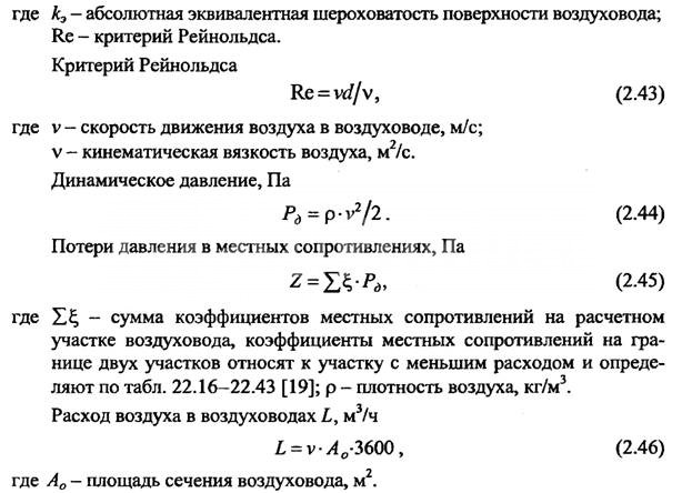
Air flow pressure loss calculation Aerodynamic calculation of air ducts according to air losses is carried out in order to select the correct sections to meet the technical requirements of the system and select the fan power. Losses are determined by the formula:

R yd - the value of specific pressure losses in all sections of the duct;
P gr – gravitational air pressure in vertical channels;
Σ l - the sum of the individual sections of the ventilation system.
The pressure loss is given in Pa, the length of the sections is determined in meters. If the movement of air flows in ventilation systems occurs due to the natural pressure difference, then the calculated pressure drop Σ = (Rln + Z) for each individual section. To calculate the gravitational pressure, you need to use the formula:
P gr – gravitational pressure, Pa;
h is the height of the air column, m;
ρ n - air density outside the room, kg / m 3;
ρ in - air density inside the room, kg / m 3.
Further calculations for natural ventilation systems are performed using the formulas:
Determining the cross section of ducts
Determination of the speed of movement of air masses in gas ducts
Calculation for losses due to local resistances of the ventilation system
Determination of loss to overcome friction
Determination of the air flow velocity in the channels
The calculation begins with the most extended and remote section of the ventilation system. As a result of aerodynamic calculations of air ducts, the required mode of ventilation in the room should be provided.
The cross-sectional area is determined by the formula:
F P = L P / V T .
F P - cross-sectional area of the air channel;
L P is the actual air flow in the calculated section of the ventilation system;
V T - the speed of movement of air flows to ensure the required frequency of air exchange in the required volume.
Taking into account the results obtained, the pressure loss is determined during the forced movement of air masses through the air ducts.


Correction coefficients are applied for each material for the manufacture of air ducts, depending on the indicators of surface roughness and the speed of movement of air flows. Tables can be used to facilitate aerodynamic calculations of air ducts.
Tab. No. 1. Calculation of metal air ducts of a round profile.


Table number 2. Values of correction factors taking into account the material of manufacture of air ducts and the speed of the air flow.

The roughness coefficients used for calculations for each material depend not only on its physical characteristics, but also on the speed of air flow. The faster the air moves, the more resistance it experiences. This feature must be taken into account during the selection of a specific coefficient.
Aerodynamic calculation for air flow in square and round ducts shows different flow rates for the same cross-sectional area of the conditional passage. This is explained by differences in the nature of vortices, their significance and ability to resist movement.
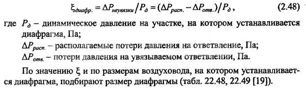
The main condition for the calculations is that the air velocity constantly increases as the area approaches the fan. With this in mind, requirements are imposed on the diameters of the channels. In this case, the parameters of air exchange in the premises must be taken into account. The locations of the inflow and outlet of the flows are selected in such a way that people staying in the room do not feel drafts. If a direct section fails to achieve a regulated result, then diaphragms with through holes are inserted into the air ducts. By changing the diameter of the holes, an optimal adjustment of the air flows is achieved. Diaphragm resistance is calculated by the formula:

The overall calculation of ventilation systems should take into account:
- Dynamic pressure of the air flow during movement. The data are consistent with the terms of reference and serve as the main criterion during the selection of a particular fan, its location and principle of operation. If it is impossible to provide the planned modes of operation of the ventilation system with one unit, several units are installed. The specific place of their installation depends on the features of the air duct circuit diagram and the permissible parameters.
- The volume (flow rate) of air masses moved in the context of each branch and room per unit of time. The initial data are the requirements of the sanitary authorities for the cleanliness of the premises and the features of the technological process of industrial enterprises.
- Inevitable pressure losses resulting from vortex phenomena during the movement of air streams at different speeds. In addition to this parameter, the actual cross section of the duct and its geometric shape are taken into account.
- Optimum speed of air movement in the main channel and separately for each branch. The indicator affects the choice of fan power and their installation locations.
To facilitate the production of calculations, it is allowed to use a simplified scheme; it is used for all premises with non-critical requirements. To guarantee the required parameters, the selection of fans by power and quantity is done with a margin of up to 15%. A simplified aerodynamic calculation of ventilation systems is performed according to the following algorithm:
- Determination of the cross-sectional area of the channel depending on the optimal speed of the air flow.
- Selection of a standard channel section close to the calculated one. Specific indicators should always be selected upwards. Air ducts may have increased technical indicators, it is prohibited to reduce their capabilities. If it is impossible to select standard channels in the technical conditions, their manufacture according to individual sketches is provided.
- Checking the indicators of air movement speed, taking into account the actual values of the nominal section of the main channel and all branches.
The task of aerodynamic calculation of air ducts is to provide the planned indicators of ventilation of premises with minimal loss of financial resources. At the same time, at the same time, it is necessary to achieve a reduction in the labor intensity and metal consumption of construction and installation works, ensuring the reliability of the operation of the installed equipment in various modes.
Special equipment must be mounted in accessible places, it must be freely accessible for routine technical inspections and other work to maintain the system in working order.
According to the provisions of GOST R EN 13779-2007 for calculating the ventilation efficiency ε v you need to apply the formula:

with EHA- indicators of the concentration of harmful compounds and suspended solids in the exhaust air;
with IDA- the concentration of harmful chemical compounds and suspended solids in the room or working area;
c sup- indicators of pollution coming from the supply air.
The efficiency of ventilation systems depends not only on the power of the connected exhaust or blowing devices, but also on the location of air pollution sources. During the aerodynamic calculation, minimum performance indicators for the system should be taken into account.
Specific power (P Sfp > W∙s / m 3) of fans is calculated by the formula:
de P is the power of the electric motor installed on the fan, W;
q v - air flow rate supplied by fans during optimal operation, m 3 / s;
∆ p is an indicator of the pressure drop at the inlet and outlet of air from the fan;
η tot is the overall efficiency for the electric motor, air fan and air ducts.
During calculations, the following types of air flows are taken into account according to the numbering on the diagram:
Scheme 1. Types of air flows in the ventilation system.
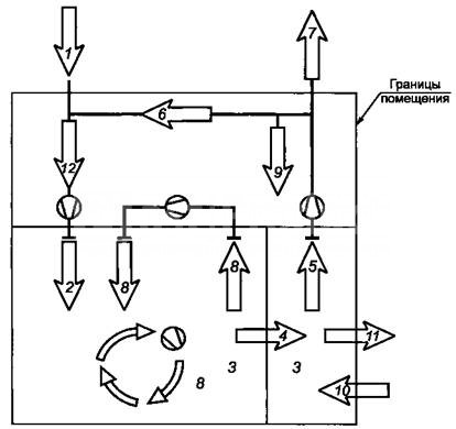
- External, enters the air conditioning system from the external environment.
- Supply. Air streams supplied to the duct system after preliminary preparation (heating or cleaning).
- The air in the room.
- flowing air currents. Air moving from one room to another.
- Exhaust. Air vented from a room to the outside or into a system.
- Recirculation. Part of the flow returned to the system to maintain the internal temperature at setpoints.
- Removable. Air that is expelled from the premises irrevocably.
- secondary air. Returns back to the room after cleaning, heating, cooling, etc.
- Air loss. Possible leaks due to leaky air duct connections.
- Infiltration. The process of entering the air into the premises in a natural way.
- Exfiltration. Natural air leakage from the room.
- Air mixture. Simultaneous suppression of several streams.
Each type of air has its own state standards. All calculations of ventilation systems must take them into account.
The efficiency of ventilation systems depends on the correct selection of individual elements and equipment. The calculation of the air duct area is carried out in order to ensure the required frequency of air changes in each room, depending on its purpose. Forced and natural ventilation require separate algorithms for design work, but have common directions. When determining the resistance to air flow, the geometry and material of manufacture of air ducts, their total length, kinematic diagram, and the presence of branches are taken into account. Additionally, heat energy losses are calculated to ensure a favorable microclimate and reduce the cost of maintaining the building in the winter.
The calculation of the cross-sectional area is performed on the basis of data on the aerodynamic calculation of air ducts. Taking into account the obtained values, the following is performed:
- Selection of the optimal dimensions of the cross sections of the air ducts, taking into account the normative permissible speeds of the air flow.
- Determination of the maximum pressure loss in the ventilation system, depending on the geometry, speed and features of the duct scheme.
The sequence of calculation of ventilation systems
1. Determination of calculated indicators of individual sections of the overall system. The sections are limited by tees or technological dampers, the air flow along the length of the entire section is stable. If there are branches from the site, then their air flow is summed up, and the total is determined for the site. The obtained values are displayed on the axonometric diagram.
2. Choice of the main direction of the ventilation or heating system. The main section has the largest air consumption among all allocated during the calculations. It should be the longest of all consecutive individual sections and branches. According to regulatory documents, the numbering of sections begins with the least loaded and continues with increasing air flow.
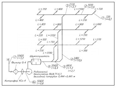
Approximate diagram of the ventilation system with designations of branches and sections
3. The parameters of the sections of the calculated sections of the ventilation system are selected taking into account the speeds recommended by the standards in the air ducts and louvered grilles. According to state standards, the air velocity in main pipelines is ≤ 8 m/s, in branches ≤ 5 m/s, in louvres ≤ 3 m/s.
Calculations for the ventilation system are carried out taking into account the existing preconditions.
Total pressure loss in air ducts:
![]()
Calculation of rectangular ducts for pressure loss:
R - specific friction losses on the air duct surface;
L is the length of the duct;
n - correction factor depending on the roughness of the air ducts.
Specific pressure losses for circular sections are determined by the formula:
λ is the coefficient of hydraulic friction resistance;
d is the diameter of the duct section;
P d - actual pressure.
To calculate the coefficient of friction resistance for a circular pipe section, the following formula is used:

During calculations, it is allowed to use tables in which, based on the above formulas, practical friction losses, dynamic pressure indicators and air flow rates for various flow rates for are determined.


It must be borne in mind that the indicators of the actual air flow in rectangular and round ducts with the same cross-sectional area are not the same even with complete equality of the air flow speeds. If the air temperature exceeds +20°C, then correction factors for friction and local resistance must be used.
The calculation of the ventilation system consists of the calculation of the main line and all branches connected to it. In this case, it is necessary to achieve a position so that the air speed constantly increases as it approaches the suction or discharge fan. If the duct scheme does not allow taking into account branch losses, and their values do not exceed 10% of the total flow, then it is allowed to use the diagram for overpressure damping. The coefficient of resistance to the air flow of the diaphragm is calculated by the formula:
The above duct calculations are suitable for the following types of ventilation:
- Exhaust. It is used to remove exhaust air from industrial, commercial, sports and residential premises. In addition, it can have special filters for cleaning the air emitted from dust or harmful chemical compounds; they can be mounted inside or outside the premises.
- supply. Prepared (heated or purified) air is supplied to the premises, it may have special devices to reduce noise levels, automate control, etc.
- Supply/exhaust. A complex of equipment and devices for supplying/removing air from premises for various purposes may have heat recovery units, which significantly reduces the cost of maintaining a favorable microclimate in the premises.
The movement of air flows through the ducts can be horizontal, vertical or angular. Taking into account the architectural features of the premises, their number and size, air ducts can be installed in several tiers in one room.
Calculation of the cross-sectional area of the pipeline
After the speed of air movement through the ducts is determined, taking into account the required exchange rate, it is possible to calculate the parameters of the cross-section of the air ducts according to the formula S = R\3600v, where S is the cross-sectional area of the air duct, R is the air flow rate in m 3 / hour, v is the speed of air movement flow, 3600 - time correction factor. The cross-sectional area allows you to determine the diameter of a round duct using the formula:
![]()
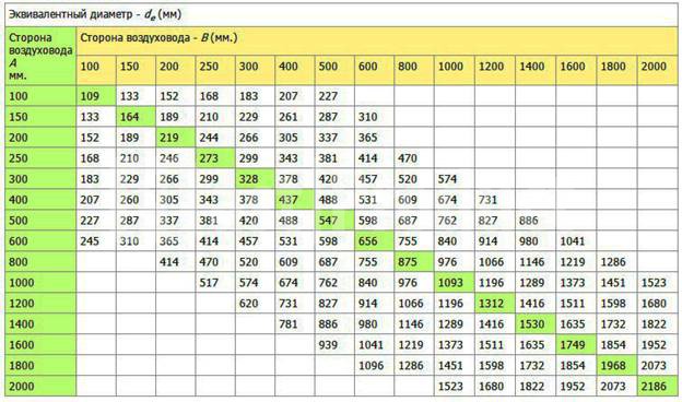
If a square duct is installed in the room, then it is calculated by the formula d e \u003d 1.30 x ((a x b) 0.625 / (a + b) 0.25).
d e - equivalent diameter for a round duct in millimeters;
a and b are the lengths of the sides of the square or rectangle in millimeters. To simplify the calculations, use the conversion table No. 1.
Table No. 1
To calculate the equivalent diameter of oval ducts, use the formula d = 1.55 S 0.625 /P 0.2
S is the cross-sectional area of the oval duct;
P is the perimeter of the pipe.
The cross-sectional area of an oval pipe is calculated by the formula S \u003d π × a × b / 4
S is the cross-sectional area of the oval duct;
a = large diameter oval duct;
b = smaller diameter of the oval duct.
Selection of oval or square air ducts according to the speed of the air flow To facilitate the selection of the optimal parameter, the designers calculated ready-made tables. With their help, you can choose the optimal size of air ducts of any section, depending on the frequency of air exchange in the premises. The frequency of exchange is selected taking into account the volume of the room and the requirements of SanPin.

Calculation of parameters of air ducts and natural ventilation systems In contrast to forced air supply/removal, for natural ventilation, indications of the difference in pressure outside and inside the premises are important. The drag calculation and direction selection must be done in such a way as to guarantee a minimum flow pressure loss.
When calculating, the existing gravitational pressures are linked with the actual pressure losses in vertical and horizontal air ducts.

Classifications of initial data during the calculation of the cross section of air ducts During calculations, it is necessary to take into account the requirements of the current SNiP 2.04.05-91 and SNiPa 41-01-2003. The calculation of ventilation systems according to the diameter of the air ducts and the equipment used should provide:
- Normalized indicators for air purity, exchange rate and indoor microclimate indicators. The power of the installed equipment is calculated. At the same time, the level of noise and vibration cannot exceed the established limits for buildings and premises, taking into account their purpose.
- The systems must be maintainable, during the scheduled maintenance work, the technological cycle of the enterprises should not be disturbed.
- In rooms with an aggressive environment, only special air ducts and equipment are provided that exclude sparking. Hot surfaces must be additionally insulated.
Standards for design conditions for determining the cross section of air ducts
The calculation of the air duct area should provide:
- Proper conditions for cleanliness and temperature conditions in the premises. For rooms with excess heat, ensure its removal, and in rooms with a lack of heat, minimize the loss of warm air. At the same time, it is necessary to adhere to the economic feasibility of fulfilling these conditions.
- The speed of air movement in the premises should not impair the comfort of people staying in the premises. This takes into account the obligatory air purification in the working areas. In the jet of air entering the room, the speed of movement Nx is determined by the formula Nx = Kn × n. The maximum inlet air temperature is determined by the formula tx = tn + D t1, and the minimum by the formula tcx = tn + D t2. Where: nn, tn - normalized air flow rate in m / s and air temperature at the workplace in degrees Celsius, K \u003d 6 (air velocity transition coefficient at the outlet of the duct and in the room), D t1, D t2 - maximum allowable deviation temperature.
- The maximum concentration of harmful chemical compounds and suspended particles according to GOST 12.1.005-88. Additionally, you need to take into account the latest decisions of the State Supervision.
- Outside air parameters. They are regulated depending on the technological features of the production process, the specific purpose of the structure and buildings. Indicators of the concentration of explosive compounds and substances must meet the requirements of fire-fighting state authorities.
Installation of ventilation systems with forced air supply / removal should be done only in cases where the characteristics of natural ventilation cannot provide the required parameters for cleanliness and temperature conditions in the premises or buildings have separate zones with a complete absence of natural air inflow. For some rooms, the area of the air ducts is selected in such a way that the backwater is constantly maintained in the rooms and the supply of outside air is excluded. This applies to pits, basements and other premises in which there is a possibility of accumulation of harmful substances. Additionally, air cooling must be present at workplaces that have a thermal exposure of more than 140 W/m 2 .
Requirements for ventilation systems If the calculated data on ventilation systems lower the temperature in the premises to + 12 ° C, then it is imperative to provide for simultaneous heating. Heating units of the appropriate power are connected to the systems in order to bring the temperature values up to those normalized by state standards. If ventilation is installed in industrial buildings or public premises in which people constantly stay, then at least two supply and two exhaust constantly operating units must be provided. The size of the area of the air ducts must provide the calculated value of air flows. For connected or adjacent rooms, it is allowed to have two exhaust systems and one supply system, or vice versa.
If the premises must be ventilated around the clock, then backup (emergency) equipment must be connected to the installed air ducts. Additional branches should be taken into account, a separate calculation of the area is made for them. A standby fan can be omitted only if:
- After the failure of the ventilation system, it is possible to quickly stop the work process or take people out of the room.
- The technical parameters of emergency ventilation fully meet the requirements for cleanliness and air temperature in the premises.
General requirements for air ducts The calculation of the final parameters of the air ducts should provide for the possibility of:
- Mounting of fire dampers in vertical or horizontal position.
- Installations on interfloor platforms of air locks. The design features of the devices must ensure that the regulatory requirements for the emergency shutdown of individual branches of the ventilation system and the prevention of the spread of smoke or fire throughout the building are met. In this case, the length of the section on which the gates are attached should not be less than two meters.
- No more than five air ducts can be connected to each floor collector. The connection node creates additional resistance to air flow, this feature must be taken into account when calculating the dimensions.
- Installation of automatic fire alarm systems. If the alarm drive is mounted inside the duct, then when determining its optimal diameter, the reduction in the effective diameter and the appearance of additional resistance to the air flow due to turbulence should be taken into account. The same requirements are put forward when installing check valves that prevent the flow of harmful chemical compounds from one production facility to another.
Air ducts made of non-combustible materials must be installed for ventilation systems with suction of flammable products or with temperatures above +80°C. The main transit sections of ventilation should be metal. In addition, metal air ducts are mounted in attics, technical rooms, basements and undergrounds.
The total air loss for fittings is determined by the formula:
![]()
Where p is the specific pressure loss per square meter of the expanded section of the duct, ∑Ai is the total expanded area. Within one installation scheme of the ventilation system, losses can be taken from the table.
During the calculation of the dimensions of the air ducts, in any case, engineering assistance will be needed, the employees of our company have enough knowledge to solve all technical issues.
Comments:
- Why do you need to know about the area of air ducts?
- How to calculate the area of the material used?
- Calculating the area of ducts
The possible concentration of indoor air contaminated with dust, water vapor and gases, products of thermal processing of food, forces the installation of ventilation systems. For these systems to be effective, serious calculations have to be made, including the calculation of the area of \u200b\u200bair ducts.
Having found out a number of characteristics of the facility under construction, including the area and volume of individual rooms, the features of their operation and the number of people who will be there, specialists, using a special formula, can establish the design ventilation performance. After that, it becomes possible to calculate the cross-sectional area of \u200b\u200bthe duct, which will provide the optimal level of ventilation of the interior.
Why do you need to know about the area of air ducts?
Ventilation of premises is a rather complicated system. One of the most important parts of the air distribution network is a complex of air ducts. Not only the correct location in the room or cost savings depends on the qualitative calculation of its configuration and working area (both the pipe and the total material necessary for the manufacture of the air duct), but most importantly, the optimal ventilation parameters that guarantee a person comfortable living conditions.
Figure 1. Formula for determining the diameter of the working line.
In particular, it is necessary to calculate the area in such a way that the result is a structure that can pass the required amount of air while meeting other requirements for modern ventilation systems. It should be understood that the correct calculation of the area leads to the elimination of air pressure losses, compliance with sanitary standards for the speed and noise level of the air flowing through the duct channels.
At the same time, an accurate idea of the area occupied by the pipes makes it possible, when designing, to allocate the most suitable place in the room for the ventilation system.
Back to index
How to calculate the area of the material used?
The calculation of the optimal duct area is directly dependent on factors such as the volume of air supplied to one or more rooms, its speed and air pressure loss.
At the same time, the calculation of the amount of material required for its manufacture depends both on the cross-sectional area (dimensions of the ventilation duct), and on the number of rooms into which fresh air must be injected, and on the design features of the ventilation system.
When calculating the size of the cross section, it should be borne in mind that the larger it is, the lower will be the speed of air passing through the duct pipes.

At the same time, there will be less aerodynamic noise in such a highway, and the operation of forced ventilation systems will require less electricity. To calculate the area of air ducts, you must apply a special formula.
To calculate the total area of the material that must be taken for the assembly of air ducts, you need to know the configuration and basic dimensions of the system being designed. In particular, for the calculation of round air distribution pipes, such quantities as the diameter and the total length of the entire line will be required. At the same time, the amount of material used for rectangular structures is calculated based on the width, height and total length of the duct.
In the general calculations of the material requirement for the entire line, bends and half-bends of various configurations must also be taken into account. So, the correct calculations of a round element are impossible without knowing its diameter and angle of rotation. Components such as the width, height and angle of rotation of the elbow are involved in calculating the material area for a rectangular bend.
It is worth noting that for each such calculation, its own formula is used. Most often, pipes and fittings are made of galvanized steel in accordance with the technical requirements of SNiP 41-01-2003 (Appendix H).
Back to index
Calculating the area of ducts

The size of the ventilation pipe is influenced by such characteristics as the array of air injected into the premises, the speed of the flow and the level of its pressure on the walls and other elements of the line.
It is enough, without calculating all the consequences, to reduce the diameter of the line, as the speed of the air flow will immediately increase, which will lead to an increase in pressure along the entire length of the system and in places of resistance. In addition to the appearance of excessive noise and unpleasant vibration of the pipe, electric ones will also record an increase in electricity consumption.
However, it is not always possible and necessary to increase the cross section of the ventilation line in the pursuit of eliminating these shortcomings. First of all, this can be prevented by the limited dimensions of the premises. Therefore, you should especially carefully approach the process of calculating the area of \u200b\u200bthe pipe.
To determine this parameter, you must apply the following special formula:
Sc \u003d L x 2.778 / V, where
Sc - calculated channel area (cm 2);
L is the flow rate of air moving through the pipe (m 3 / hour);
V is the speed of air movement along the ventilation line (m / s);
2.778 - coefficient of matching of different dimensions (for example, meters and centimeters).

The result of the calculations - the estimated area of the pipe - is expressed in square centimeters, since in these units of measurement it is considered by experts as the most convenient for analysis.
In addition to the estimated cross-sectional area of the pipeline, it is important to establish the actual cross-sectional area of the pipe. In this case, it should be borne in mind that for each of the main cross-sectional profiles - round and rectangular - its own separate calculation scheme is adopted. So, to fix the actual area of a circular pipeline, the following special formula is used.
In order for the air exchange in the house to be “correct”, an aerodynamic calculation of the air ducts is needed even at the stage of drawing up a ventilation project.
Air masses moving through the channels of the ventilation system are taken as an incompressible liquid during calculations. And this is quite acceptable, because too much pressure is not formed in the air ducts. In fact, pressure is formed as a result of air friction against the walls of the channels, and also when local resistances appear (these include it - pressure - jumps at places where the direction changes, when connecting / disconnecting air flows, in areas where control devices or where the diameter of the ventilation duct changes).
Note! The concept of aerodynamic calculation includes the determination of the cross section of each section of the ventilation network that provides the movement of air flows. Moreover, the injection resulting from these movements is also determined.

In accordance with many years of experience, we can safely say that sometimes some of these indicators are already known during the calculation. The following are situations that are often encountered in such cases.
- The cross-sectional index of the cross-channels in the ventilation system is already known, it is required to determine the pressure that may be required in order for the desired amount of gas to move. This often happens in those air conditioning lines where the sectional dimensions were based on characteristics of a technical or architectural nature.
- We already know the pressure, but we need to determine the cross section of the network to provide the ventilated room with the required amount of oxygen. This situation is inherent in natural ventilation networks, in which the already existing pressure cannot be changed.
- It is not known about any of the indicators, therefore, we need to determine both the pressure in the line and the cross section. This situation occurs in most cases in the construction of houses.

Features of aerodynamic calculations
Let us get acquainted with the general procedure for carrying out such calculations, provided that both the cross section and the pressure are unknown to us. Let's make a reservation right away that the aerodynamic calculation should be carried out only after the required volumes of air masses have been determined (they will pass through the air conditioning system) and the approximate location of each of the air ducts in the network has been designed.

And in order to carry out the calculation, it is necessary to draw an axonometric diagram, in which there will be a list of all network elements, as well as their exact dimensions. In accordance with the plan of the ventilation system, the total length of the air ducts is calculated. After that, the entire system should be divided into segments with homogeneous characteristics, according to which (only separately!) The air flow will be determined. What is typical, for each of the homogeneous sections of the system, a separate aerodynamic calculation of the air ducts should be carried out, because each of them has its own speed of movement of air flows, as well as a permanent flow rate. All the indicators obtained must be entered into the axonometric scheme already mentioned above, and then, as you probably already guessed, you need to select the main highway.
How to determine the speed in the ventilation ducts?
As can be judged from all that has been said above, it is necessary to choose as the main highway that chain of successive segments of the network that is the longest; in this case, the numbering should begin exclusively from the most remote section. As for the parameters of each of the sections (and these include air flow, section length, its serial number, etc.), they should also be entered in the calculation table. Then, when the introduction is finished, the cross-sectional shape is selected and its - sections - dimensions are determined.

LP/VT=FP.
What do these abbreviations stand for? Let's try to figure it out. So in our formula:
- LP is the specific air flow in the selected area;
- VT is the speed at which the air masses move through this area (measured in meters per second);
- FP - this is the cross-sectional area of the channel we need.
Tellingly, when determining the speed of movement, it is necessary to be guided, first of all, by considerations of economy and noise of the entire ventilation network.
Note! According to the indicator obtained in this way (we are talking about the cross section), it is necessary to select an air duct with standard values, and its actual cross section (indicated by the abbreviation FF) should be as close as possible to the previously calculated one.
LP/ FФ = VФ.
Having received the indicator of the required speed, it is necessary to calculate how much the pressure in the system will decrease due to friction against the walls of the channels (for this, you need to use a special table). As for the local resistance for each of the sections, they should be calculated separately, and then summarized into a general indicator. Then, by summing up the local resistance and the losses due to friction, you can get the total loss in the air conditioning system. In the future, this value will be used to calculate the required amount of gas masses in the ventilation ducts.

Air heating unit
Earlier we talked about what an air-heating unit is, talked about its advantages and areas of application, in addition to this article, we advise you to familiarize yourself with this information
How to calculate the pressure in the ventilation network
In order to determine the expected pressure for each individual section, you must use the formula below:
H x g (PH - PB) \u003d DPE.
Now let's try to figure out what each of these abbreviations means. So:
- H in this case denotes the difference in the marks of the mine mouth and the intake grate;
- РВ and РН is an indicator of gas density, both outside and inside the ventilation network, respectively (measured in kilograms per cubic meter);
- Finally, DPE is a measure of what the natural available pressure should be.
We continue to disassemble the aerodynamic calculation of air ducts. To determine the internal and external density, it is necessary to use a reference table, and the temperature indicator inside / outside must also be taken into account. As a rule, the standard temperature outside is taken as plus 5 degrees, and regardless of in which particular region of the country construction work is planned. And if the temperature outside is lower, then as a result the injection into the ventilation system will increase, due to which, in turn, the volumes of incoming air masses will be exceeded. And if the temperature outside, on the contrary, is higher, then the pressure in the line will decrease because of this, although this trouble, by the way, can be completely compensated by opening the vents / windows.

As for the main task of any described calculation, it consists in choosing such air ducts, where the losses on the segments (we are talking about the value? (R * l *? + Z)) will be lower than the current DPE indicator, or, alternatively, at least equal to him. For greater clarity, we present the moment described above in the form of a small formula:
DPE? ?(R*l*?+Z).
Now let's take a closer look at what the abbreviations used in this formula mean. Let's start from the end:
- Z in this case is an indicator indicating a decrease in the speed of air movement due to local resistance;
- ? - this is the value, more precisely, the coefficient of what is the roughness of the walls in the line;
- l is another simple value that indicates the length of the selected section (measured in meters);
- finally, R is an indicator of friction losses (measured in pascals per meter).


![]()
Well, we figured it out, now let's find out a little more about the roughness index (that is?). This indicator depends only on what materials were used in the manufacture of channels. It is worth noting that the speed of air movement can also be different, so this indicator should also be taken into account.
Speed - 0.4 meters per second
In this case, the roughness index will be as follows:
- for plaster with the use of reinforcing mesh - 1.48;
- for slag gypsum - about 1.08;
- for an ordinary brick - 1.25;
- and for cinder concrete, respectively, 1.11.
Speed - 0.8 meters per second
Here, the described indicators will look like this:
- for plaster with the use of reinforcing mesh - 1.69;
- for slag gypsum - 1.13;
- for ordinary brick - 1.40;
- finally, for slag concrete - 1.19.
Let's slightly increase the speed of the air masses.
Speed - 1.20 meters per second
For this value, the roughness indicators will be as follows:
- for plaster with the use of reinforcing mesh - 1.84;
- for slag gypsum - 1.18;
- for an ordinary brick - 1.50;
- and, consequently, for slag concrete - somewhere around 1.31.
And the last indicator of speed.
Speed - 1.60 meters per second
Here the situation will look like this:
- for plaster using a reinforcing mesh, the roughness will be 1.95;
- for slag gypsum - 1.22;
- for ordinary brick - 1.58;
- and, finally, for slag concrete - 1.31.
Note! We figured out the roughness, but it is worth noting one more important point: in this case, it is desirable to take into account a small margin, fluctuating within ten to fifteen percent.
We deal with the general ventilation calculation
When making an aerodynamic calculation of air ducts, you must take into account all the characteristics of the ventilation shaft (these characteristics are listed below).
- Dynamic pressure (to determine it, the formula is used - DPE? / 2 \u003d P).
- The flow of air masses (it is denoted by the letter L and is measured in cubic meters per hour).
- Pressure loss due to friction of air against the internal walls (denoted by the letter R, measured in pascals per meter).
- Air duct diameter (to calculate this indicator, the following formula is used: 2 * a * b / (a + b); in this formula, the values \u200b\u200bof a, b are the dimensions of the cross section of the channels and are measured in millimeters).
- Finally, speed is V, measured in meters per second, as we mentioned earlier.
 >
>
As for the actual sequence of actions in the calculation, it should look something like this.
Step one. First, the required channel area should be determined, for which the following formula is used:
I/(3600xVpek) = F.
Understanding the meanings:
- F in this case is, of course, the area, which is measured in square meters;
- Vpek is the desired air speed, which is measured in meters per second (for channels, a speed of 0.5-1.0 meters per second is taken, for mines - about 1.5 meters).
Step three. The next step is to determine the appropriate duct diameter (indicated by the letter d).
Step four. Then the remaining indicators are determined: pressure (denoted as P), speed of movement (abbreviated as V) and, therefore, decrease (abbreviated as R). For this, it is necessary to use nomograms according to d and L, as well as the corresponding tables of coefficients.
Step Five. Using already other tables of coefficients (we are talking about indicators of local resistance), it is required to determine how much the effect of air will decrease due to local resistance Z.
Step six. At the last stage of calculations, it is necessary to determine the total losses in each individual section of the ventilation line.
Pay attention to one important point! So, if the total losses are below the already existing pressure, then such a ventilation system can be considered effective. But if the losses exceed the pressure indicator, then it may be necessary to install a special throttle diaphragm in the ventilation system. Thanks to this diaphragm, excess pressure will be extinguished.
We also note that if the ventilation system is designed to serve several rooms at once, for which the air pressure must be different, then during the calculation it is necessary to take into account the underpressure or back pressure indicator, which must be added to the total loss indicator.
Video - How to make calculations using the program "VIKS-STUDIO"
Aerodynamic calculation of air ducts is considered a mandatory procedure, an important component of planning ventilation systems. Thanks to this calculation, you can find out how efficiently the premises are ventilated with a particular section of the channels. And the effective functioning of ventilation, in turn, ensures the maximum comfort of your stay in the house.
Calculation example. The conditions in this case are as follows: an administrative building, has three floors.

Although there are many programs for it, many parameters are still defined the old fashioned way, using formulas. The calculation of the ventilation load, area, power and parameters of individual elements is carried out after drawing up the diagram and distributing the equipment.
This is a difficult task that only professionals can do. But if you need to calculate the area of some ventilation elements or the cross section of air ducts for a small cottage, you can really do it yourself.
Air exchange calculation

If there are no toxic emissions in the room or their volume is within acceptable limits, air exchange or ventilation load is calculated by the formula:
R= n * R1,
here R1- air requirement of one employee, in cubic meters per hour, n- the number of permanent employees in the premises.
If the volume of the room per employee is more than 40 cubic meters and natural ventilation is working, it is not necessary to calculate the air exchange.
For domestic, sanitary and auxiliary premises, the calculation of ventilation by hazards is carried out on the basis of the approved norms of the air exchange rate:
- for administrative buildings (hood) - 1.5;
- halls (serving) - 2;
- conference rooms for up to 100 people with a capacity (for supply and exhaust) - 3;
- rest rooms: supply 5, extract 4.
For industrial premises in which hazardous substances are constantly or periodically released into the air, ventilation is calculated according to hazards.
Air exchange by hazards (vapors and gases) is determined by the formula:
Q= K\(k2- k1),
here To- the amount of steam or gas appearing in the building, in mg / h, k2- the content of steam or gas in the outflow, usually the value is equal to the MPC, k1- the content of gas or steam in the inflow.
The concentration of hazards in the inflow is allowed up to 1/3 of the MPC.
For rooms with the release of excess heat, air exchange is calculated by the formula:
Q= Ghut\c(tyx - tn),
here Gib- excess heat drawn to the outside, measured in W, with- specific heat by mass, c=1 kJ, tyx- the temperature of the air removed from the room, tn- supply temperature.
Heat Load Calculation

The calculation of the heat load on ventilation is carried out according to the formula:
Qin =Vn*k * p * CR(text -tnro),
in the formula for calculating the heat load on ventilation Vн- external volume of the building in cubic meters, k- air exchange rate, tvn- the temperature in the building is average, in degrees Celsius, tnro- outside air temperature used in heating calculations, in degrees Celsius, R- air density, in kg / cubic meter, Wed- heat capacity of air, in kJ \ cubic meter Celsius.
If the air temperature is lower tnro the air exchange rate decreases, and the heat consumption indicator is considered equal to Qv, a constant value.
If, when calculating the heat load on ventilation, it is impossible to reduce the air exchange rate, the heat consumption is calculated from the heating temperature.
Heat consumption for ventilation
The specific annual heat consumption for ventilation is calculated as follows:
Q=*b*(1-E),
in the formula for calculating the heat consumption for ventilation Qo- total heat loss of the building during the heating season, Qb- household heat inputs, Qs- heat input from outside (sun), n- coefficient of thermal inertia of walls and ceilings, E- reduction factor. For individual heating systems 0,15 , for central 0,1 , b- heat loss coefficient:
- 1,11 - for tower buildings;
- 1,13 - for multi-section and multi-access buildings;
- 1,07 - for buildings with warm attics and cellars.
Calculation of duct diameter

Diameters and sections are calculated after the general scheme of the system is drawn up. When calculating the diameters of ventilation ducts, the following indicators are taken into account:
- Air volume (supply or exhaust), which must pass through the pipe for a given period of time, cubic meters per hour;
- The speed of air movement. If, when calculating the ventilation pipes, the flow rate is underestimated, air ducts of too large a section will be installed, which entails additional costs. Excessive speed leads to the appearance of vibrations, increased aerodynamic hum and increased equipment power. The speed of movement on the inflow is 1.5 - 8 m / s, it varies depending on the site;
- Ventilation pipe material. When calculating the diameter, this indicator affects the resistance of the walls. For example, black steel with rough walls has the highest resistance. Therefore, the calculated diameter of the ventilation duct will have to be slightly increased compared to the norms for plastic or stainless steel.
Table 1. Optimum air flow rate in ventilation pipes.
When the throughput of future air ducts is known, it is possible to calculate the cross section of the ventilation duct:
S= R\3600 v,
here v- the speed of the air flow, in m / s, R- air consumption, cubic meters \ h.
The number 3600 is a time factor.
![]()
here: D- diameter of the ventilation pipe, m.
Calculation of the area of ventilation elements
The calculation of the ventilation area is necessary when the elements are made of sheet metal and it is necessary to determine the quantity and cost of the material.
The ventilation area is calculated by electronic calculators or special programs, which can be found in many on the Internet.
We will give several tabular values of the most popular ventilation elements.
| Diameter, mm | Length, m | |||
| 1 | 1,5 | 2 | 2,5 | |
| 100 | 0,3 | 0,5 | 0,6 | 0,8 |
| 125 | 0,4 | 0,6 | 0,8 | 1 |
| 160 | 0,5 | 0,8 | 1 | 1,3 |
| 200 | 0,6 | 0,9 | 1,3 | 1,6 |
| 250 | 0,8 | 1,2 | 1,6 | 2 |
| 280 | 0,9 | 1,3 | 1,8 | 2,2 |
| 315 | 1 | 1,5 | 2 | 2,5 |
table 2. The area of straight circular ducts.
The value of the area in square meters. at the intersection of the horizontal and vertical lines.
| Diameter, mm | Angle, degrees | ||||
| 15 | 30 | 45 | 60 | 90 | |
| 100 | 0,04 | 0,05 | 0,06 | 0,06 | 0,08 |
| 125 | 0,05 | 0,06 | 0,08 | 0,09 | 0,12 |
| 160 | 0,07 | 0,09 | 0,11 | 0,13 | 0,18 |
| 200 | 0,1 | 0,13 | 0,16 | 0,19 | 0,26 |
| 250 | 0,13 | 0,18 | 0,23 | 0,28 | 0,39 |
| 280 | 0,15 | 0,22 | 0,28 | 0,35 | 0,47 |
| 315 | 0,18 | 0,26 | 0,34 | 0,42 | 0,59 |
Table 3. Calculation of the area of bends and semi-branches of circular cross section.
Calculation of diffusers and grilles

Diffusers are used to supply or remove air from a room. The purity and temperature of the air in every corner of the room depends on the correct calculation of the number and location of ventilation diffusers. If you install more diffusers, the pressure in the system will increase, and the speed will decrease.
The number of ventilation diffusers is calculated as follows:
N= R\(2820 * v *D*D),
here R- throughput, in cubic meters / hour, v- air speed, m/s, D- diameter of one diffuser in meters.
The number of ventilation grilles can be calculated using the formula:
N= R\(3600 * v * S),
here R- air consumption in cubic meters per hour, v- air velocity in the system, m/s, S- cross-sectional area of one lattice, sq.m.
Calculation of the duct heater

The calculation of the electrical type ventilation heater is as follows:
P= v * 0,36 * ∆ T
here v- the volume of air passed through the heater in cubic meters / hour, ∆T- the difference between the air temperature outside and inside, which must be provided to the heater.
This indicator varies between 10 - 20, the exact figure is set by the client.
The calculation of the heater for ventilation begins with the calculation of the frontal cross-sectional area:
Af=R * p\3600 * vp,
here R- inflow flow rate, cubic meters per hour, p- density of atmospheric air, kg\cubic meters, vp- mass air velocity in the area.
The section size is necessary to determine the dimensions of the ventilation heater. If, according to the calculation, the cross-sectional area turns out to be too large, it is necessary to consider the option of a cascade of heat exchangers with a total calculated area.
The mass velocity index is determined through the frontal area of the heat exchangers:
vp= R * p\3600 * Af.fact
For further calculation of the ventilation heater, we determine the amount of heat required to warm the air flow:
Q=0,278 * W * c (TP-Ty),
here W- consumption of warm air, kg / hour, Tp- supply air temperature, degrees Celsius, That- outdoor air temperature, degrees Celsius, c- specific heat capacity of air, constant value 1.005.
To create a favorable microclimate in industrial and residential premises, it is necessary to install a high-quality ventilation system. Particular attention must be paid to the length and diameter of the pipe for natural ventilation, since the efficiency, performance and reliability of air ducts depend on the correct calculations.
What are the requirements for ventilation pipes?
The main purpose of the duct for natural ventilation is to remove exhaust air from the room.

When laying systems in homes, offices and other facilities, the following points must be considered:
- the diameter of the pipe for natural ventilation must be at least 15 cm;
- when installing in residential premises and at food industry facilities, anti-corrosion characteristics are important, otherwise metal surfaces will rust under the influence of high humidity;
- the lighter the weight of the structure, the easier the installation and maintenance;
- performance also depends on the thickness of the duct, the thinner, the greater the throughput;
- fire safety level - no harmful substances should be released during combustion.
If you do not follow the standards (norms) when designing, installing and choosing the material of manufacture and the diameter of PVC ventilation pipes or galvanized steel, then the air in the rooms will be “heavy” due to high humidity and lack of oxygen. In apartments and houses with poor ventilation, windows often fog up, walls in the kitchen smoke, and fungus forms.
What material to choose an air duct?
There are several types of pipes on the market, differing from each other in the material of manufacture:
Advantages of plastic pipes:
- low cost when compared with air ducts made of other materials;
- anti-corrosion surfaces do not need additional protection or treatment;
- ease of maintenance, when cleaning, you can use any detergent;
- a large selection of PVC pipe diameters for ventilation pipes;
- simple installation, also, if necessary, the structure can be easily dismantled;
- dirt does not accumulate on the surface due to smoothness;
- when heated, there is no release of harmful and toxic substances for human health.

Metal air ducts are made of galvanized or stainless steel, when considering the characteristics, the following advantages can be distinguished:
- galvanized and stainless pipes are allowed to be used at facilities with high humidity and frequent temperature changes;
- moisture resistance - structures are not subject to the formation of corrosion and rust;
- high heat resistance;
- relatively small weight;
- easy installation - basic knowledge required.

Aluminum foil is used as a material for the manufacture of corrugated air ducts. Main advantages:
- during installation, a minimum number of connections is formed;
- ease of dismantling;
- if necessary, the pipeline is placed at any angle.
Advantages of fabric structures:
- mobility - easy to install and dismantle;
- there are no problems during transportation;
- lack of condensate under any operating conditions;
- low weight facilitates the fastening process;
- no additional insulation required.
What are the types of air ducts?
Depending on the scope and direction of use, not only the diameters of PVC pipes are selected, but also the shape:

- Spiral forms are distinguished by increased rigidity and attractive appearance. During installation, the connections are made using a cardboard or rubber seal and flanges. Systems do not need isolation.
Advice! If there is no experience in this area, then in order to save your own money and time, it is better to immediately contact the specialists, since it will be very problematic to calculate the diameter of the pipe for ventilation, taking into account the air flow, and to carry out the installation yourself.
- For residential buildings (country and country houses), flat forms are ideal due to the following advantages:
- if necessary, round and flat pipes can be easily combined;
- if the dimensions do not match, then the parameters are easily adjusted using a construction knife;
- structures differ in relatively small mass;
- tees and flanges are used as connecting elements.
- Installation of flexible structures takes place without additional elements for connection (flanges, etc.), which greatly simplifies the installation process. The material used is laminated polyester film, woven fabric or aluminum foil.
- Round air ducts are more in demand, the demand is explained by the following advantages:
- minimum number of connecting elements;
- simple operation;
- air is well distributed;
- high rates of rigidity;
- simple installation work.
The material of manufacture and the shape of the pipes are determined at the stage of development of project documentation, a large list of items is taken into account here.
How is the diameter of the ventilation pipe determined?
On the territory of Russia, there are a number of SNiP regulatory documents that say how to calculate the diameter of a pipe for natural ventilation. The choice is based on the frequency of air exchange - a determining indicator of how much and how many times per hour the air in the room is replaced.
First you need to do the following:
- the volume of each room in the building is calculated - you need to multiply the length, height and width;
- air volume is calculated by the formula: L=n (normalized air exchange rate)*V (room volume);
- the obtained indicators L are rounded up to a multiple of 5;
- the balance is drawn up so that the exhaust and supply air flows coincide in the total volume;
- the maximum speed in the central duct is also taken into account, the indicators should not be more than 5 m / s, and in the branch sections of the network not more than 3 m / s.
The diameter of PVC ventilation pipes and other materials is selected according to the data obtained from the table below:

How to determine the length of the ventilation pipe?
When writing a project, in addition to calculating the diameter of the pipe for natural ventilation, an important point is to determine the length of the outer part of the duct. The total value includes the length of all channels in the building through which air circulates and is discharged outside.
Calculations are made according to the table:

The following indicators are taken into account in the calculation:
- if a flat duct is used on a roof installation, the minimum length must be 0.5 m;
- when installing a ventilation pipe next to the flue, the height is made the same in order to prevent smoke from entering the room during the heating season.
The performance, efficiency and uninterrupted operation of the ventilation system largely depends on the correct calculations and compliance with installation requirements. It is better to choose trusted companies with a positive reputation!
It is not always possible to invite a specialist to design a system of engineering networks. What to do if during the repair or construction of your facility, the calculation of ventilation ducts was required? Is it possible to make it on your own?
The calculation will allow you to create an effective system that will ensure the uninterrupted operation of units, fans and air handling units. If everything is calculated correctly, this will reduce the cost of purchasing materials and equipment, and subsequently on further maintenance of the system.
Calculation of air ducts of the ventilation system for rooms can be carried out by different methods. For example, like this:
- constant pressure loss;
- allowed speeds.
Types and types of air ducts
Before calculating networks, you need to determine what they will be made of. Nowadays, products made of steel, plastic, fabric, aluminum foil, etc. are used. Air ducts are often made of galvanized or stainless steel, this can be arranged even in a small workshop. Such products are convenient to mount and the calculation of such ventilation does not cause problems.
In addition, air ducts may differ in appearance. They can be square, rectangular and oval. Each type has its own merits.
- Rectangular allow you to make ventilation systems of small height or width, while maintaining the desired cross-sectional area.
- There is less material in round systems,
- Oval combine the pros and cons of other types.
For an example of calculation, we will choose round pipes made of tin. These are products that are used for ventilation of housing, office and retail space. The calculation will be carried out by one of the methods that allows you to accurately select the network of air ducts and find its characteristics.
Method for calculating air ducts by the method of constant speeds
You need to start with a floor plan.
Using all the norms, determine the required amount of air in each zone and draw a wiring diagram. It shows all gratings, diffusers, cross-section changes and taps. The calculation is made for the most remote point of the ventilation system, divided into sections limited by branches or gratings.

The calculation of the air duct for installation consists in choosing the desired section along the entire length, as well as finding the pressure loss for selecting a fan or supply unit. The initial data are the values of the amount of passing air in the ventilation network. Using the scheme, we will calculate the diameter of the duct. To do this, you need a pressure loss graph.
For each type of air duct, the schedule is different. Usually, manufacturers provide such information for their products, or you can find it in reference books. Let's calculate round tin air ducts, the graph for which is shown in our figure.

Nomogram for size selection
According to the chosen method, we set the air velocity of each section. It must be within the limits for buildings and premises of the selected purpose. For the main air supply and exhaust ventilation ducts, the following values are recommended:
- living quarters - 3.5–5.0 m/s;
- production - 6.0–11.0 m/s;
- offices - 3.5–6.0 m/s.
For branches:
- offices - 3.0–6.5 m/s;
- living quarters - 3.0–5.0 m/s;
- production - 4.0–9.0 m/s.
When the speed exceeds the permissible level, the noise level rises to an uncomfortable level for a person.
After determining the speed (in the example 4.0 m/s), we find the desired section of the air ducts according to the graph. There are also pressure losses per 1 m of the network, which will be needed for the calculation. The total pressure loss in Pascals is found by multiplying the specific value by the length of the section:
Manual=Man·Man.
Network elements and local resistances
Losses on network elements (lattices, diffusers, tees, turns, changes in section, etc.) are also important. For lattices and some elements, these values are specified in the documentation. They can also be calculated by multiplying the coefficient of local resistance (c.m.s.) by the dynamic pressure in it:
Rm. s.=ζ Rd.
Where Rd=V2 ρ/2 (ρ is the air density).
K. m. s. determined from reference books and factory characteristics of products. We summarize all types of pressure losses for each section and for the entire network. For convenience, we will do this in a tabular way.

The sum of all pressures will be acceptable for this duct network and the branch losses must be within 10% of the total available pressure. If the difference is greater, it is necessary to mount dampers or diaphragms on the outlets. To do this, we calculate the required c.m.s. according to the formula:
ζ= 2Rizb/V2,
where Pizb is the difference between available pressure and branch losses. According to the table, select the diameter of the diaphragm.

The required diameter of the diaphragm for air ducts.
The correct calculation of ventilation ducts will allow you to choose the right fan by choosing from manufacturers according to your criteria. Using the found available pressure and the total air flow in the network, this will be easy to do.


