Joining timber elements has the task of linking mating building materials, such as edged beams, so that they do not move relative to each other. According to the position and direction of the connected wooden elements, longitudinal joints and corner joints, as well as joints on branches and crosshairs, are distinguished. Spatial sheet steel connectors and pre-drilled steel sheet escutcheons often replace carpentry connections.
Connections that must transmit forces of a certain magnitude and direction, such as compressive forces, are also called joints of connected wooden elements as rods, such as compressed rods. Compressed rods connected at an acute angle can be connected at notches. Other connections of wooden structures are arranged at the expense of joints of wooden elements using connecting means.
According to the type of connecting means, such connections are called nail or bolt, dowel or dowel connections. In the construction of wood, glued building structures are also used. Since they have particular advantages, the use of glued timber structures is of increasing importance.
Longitudinal connections
There are longitudinal connections on the supports and longitudinal connections in the span. Above the supports, perpendicular trunnions are used, a joint “in the paw” and a partially trunnion joint “in the paw” (Fig. 1). To reinforce these joints, building brackets made of flat or round steel can be driven in from above or from the side. Often, wooden elements are joined head-on and fixed only with building brackets. If, however, large tensile forces act at the joint, for example, at the girders on the roof rafters, then both elements are joined head-on on the support and connected by side plates made of boards or perforated strips of steel protected from corrosion.
Rice. 1. Longitudinal connections
Runs can also be made in the form cantilever-suspended(Gerber runs) or hinged girders. They have a joint located in a place determined by the calculation, not far from the support, in which the bending moments are equal to zero and where there are no bending forces (Fig. 2). There, the runs are connected with a straight or oblique overlay. The incoming purlin is held in place by a screw bolt, also called a pivot bolt. The swivel bolt with washers must bear the load from the suspended purlin.

Rice. 2. Longitudinal joints of Gerber girders
Gerber purlins with a seam lying on top are impractical, since there is a danger that the purlins at the edge of the seam will come off. With a suspended joint, having screwed up, there is no danger of separation.
To connect the Gerber purlins, spatial elements made of steel sheet are also used, which are also called Gerber connecting elements. They are attached with nails along the front butted ends of the runs (see Fig. 2).
Corner connections
Corner joints are necessary when two logs or beams in a corner are joined at a right or approximately right angle in the same plane. The most commonly used types of joints are cut-out trunnions, a smooth angular foot and a compressed foot (Fig. 3). With the help of cut-out trunnions and smooth corner legs, the ends of thresholds, girders and rafter legs lying on supports or protruding cantilevered are connected. Nails or screw bolts can be used to secure the joints. The compressed paw has planes obliquely entering each other. It is particularly suitable for connecting loaded, fully supported thresholds.

Rice. 3. Corner joints
Branches
When branching, a beam suitable at a right or oblique angle in most cases is superficially joined to another beam. In normal cases, a joint on the trunnions is used, and in secondary structures, the joint "in the paw" is also used. In addition, beams made of timber can be joined using metal spatial connecting elements. In trunnion joints, the thickness of the trunnion is approximately one third of the thickness of the timber. The trunnions have a length in most cases from 4 to 5 cm. The groove for the trunnion is made 1 cm deeper so that the compression force is transmitted not through the section of the trunnion, but through a large area of the remaining section of the bars.
When arranging trunnions, normal trunnions are distinguished, passing through the entire width of the beam, and protruding(hemp) pins, which are used for connections at the ends of the bars (Fig. 4). If the bars in the connection do not fit at right angles to each other, for example, at the corner struts, then the trunnion at the strut must be made at right angles to the horizontal (or vertical) structural element (see Fig. 4).

Rice. 4. Pin connections
When installing trunnions in wooden beams and girders, the trunnion must bear the entire load. It is more advantageous to make such connections using beam shoes from corrosion-protected steel (Fig. 9). These shoes are fixed with special nails in such a way as to prevent them from buckling and turning relative to the joint. In addition, the cross section of the beam is not weakened by the trunnion holes.
Cross connections
Wooden beams can intersect in the same plane or with offset planes and be overhead or support. Bars intersecting in the same plane can intersect "IN THE LAPU" if the weakening of the section does not play any role (Fig. 5). It is advisable to tie the intersecting overhead thresholds on the support beams with round dowels (pins) made of hard wood or steel 10 to 12 cm long (Fig. 6).

Rice. 5. Connection "in the paw"

Rice. 6. Connection with round dowels (pins)
The beams joining on the side receive good support on the pole if their connection is made “In the groove” (Fig. 7). To do this, the intersection planes of both elements are cut to a depth of 1.5 to 2.0 cm. This results in an immovable connection, which is fixed with a screw bolt.

Rice. 7. Groove connection
When joining inclined and horizontal beams, as is usually the case when joining rafter legs with girders - thresholds, a cutout is made in the rafter leg corresponding to the slope, which is called sidebar(Fig. 8).

Rice. 8. Insert rafter leg
The depth of the tie-in in the rafter legs with a normal section height of 16 to 20 cm is from 2.5 to 3.5 cm. One nail is used for fastening, penetrating the threshold for a length of at least 12 cm, or a special anchor for attaching the rafters to the girders.

Rice. 9. Steel shoe connection
cuts
When cutting, a compressed rod entering at an acute angle is connected to another beam using one or more force-transmitting planes on its front side. According to the number and position of the force-transmitting planes, a frontal cut, a cut with a tooth, and a double front cut with a tooth are distinguished.
At frontal cutting(also called a frontal stop), the receiving beam has a wedge-shaped cutout that matches the shape of the end of the compressed rod (Fig. 10). The frontal plane should pass at an angle dividing the obtuse outer corner of the cut in half. The fastening bolt must also have the same direction, guaranteeing the joint from lateral displacement. To mark the cut, parallels are drawn at the same distance from the sides of the corner, which must be divided in half. The connecting line between the point of their intersection and the vertex of an obtuse angle will be the bisector of this angle (see Fig. 10). The position of the fastening bolt is obtained if the distance between the bisector and the end of the notch is divided into three parts parallel to the bisector (see Fig. 10).

Rice. 10. Frontal cutting
Under the action of a compressive force, the wood lying in front of the frontal part of the compressed rod works on slice(see fig. 10). Since the permissible stress on the cut of wood along the fibers is relatively small (0.9 MN / m 2), the plane of the wood in front of the cut edge (cut plane) must be large enough. Since, in addition, cracking due to shrinkage should be taken into account, with rare exceptions, the length of the cut plane should not be less than 20 cm.
At reverse or notched cut the cutting plane is cut at a right angle to the lower side of the compressed rod (Fig. 11). Due to the fact that due to an eccentric connection in a notched notch there may be a risk of splitting the compressed rod, it is necessary that the free end of the notch does not fit tightly against the support rod and a seam is provided between them.

Rice. 11. Serrated notch
double cut consists, as a rule, of a frontal cut in combination with a toothed cut (Fig. 12). The direction of the cutting planes is similar to that used for each of the cuttings of this combination. However, the notched cut in this case must be at least 1 cm deeper so that its cut plane is below the cut plane of the frontal cut. The fastening bolt should run parallel to the front of the notch approximately midway between the bisector and the top of the acute joint angle.

Rice. 12. Double notch
Cutting depth t v is limited according to DIN 1052. The decisive factors for this are the contact angle (a) and the height h of the cut rod (Table 1).
Pin and bolt connections
In the case of pin and bolt connections, wooden beams or boards that are in contact with the sides are connected by cylindrical connecting elements, such as rod dowels, bolts with countersunk heads and nuts, ordinary bolts with nuts. These rod dowels and bolts should prevent the wooden elements from moving in the connection plane, which is also called the shear plane. In this case, forces act perpendicular to the axis of the rod dowel or bolt. Dowels and bolts at the same time work on bending. In the connected wooden elements, all efforts are concentrated on the inner surface of the holes for dowels or bolts.
The number of rod dowels and bolts installed at the junction depends on the magnitude of the transmitted force. In this case, as a rule, at least two such elements should be installed (Fig. 13).

Rice. 13. Connection with rod dowels
In one connection, many shear planes can be located next to each other. According to the number of cut planes that are connected by the same connecting elements, single-cut, double-cut and multi-cut dowel and bolted connections are distinguished (Fig. 14). According to DIN 1052, single shear load-bearing connections with dowel pins must have at least four dowel pins.

Rice. 14. Bolted connections
For bolted connections, mainly bolts with nuts made of steel with a normalized diameter of 12, 16, 20 and 24 mm are used. In order to prevent the head and nut of the bolt from cutting into the tree, strong steel washers should be placed under them. The minimum dimensions of these washers are given for various bolt diameters in DIN 1052 (Table 2).
In order to prevent splitting of the wooden elements to be connected by rod dowels and bolts, these connecting means must have installed minimum distances between themselves, as well as from the loaded and unloaded ends. The minimum distances depend on the direction of the force, on the direction of the wood fibers and on the diameter of the dowel or bolt db and do (fig. 15 and 16). For load-bearing bolts with nuts, greater distances must be maintained between themselves and from the loaded end than in the case of rod dowels and bolts with hidden heads. On the other hand, rod dowels or bolts with hidden heads close to each other in the direction of the wood fibers should be spaced apart from the cut line so that the joints do not crack (see Fig. 15).

Rice. 15. Minimum distances in case of rod dowels and hidden head bolts

Rice. 16. Minimum distances in case of bearing bolts
Holes for pins and bolts are pre-drilled perpendicular to the cutting plane. For this, electric drills with a bed with parallel movement are used. For pins when drilling holes in wood, as well as when drilling holes in wood and metal connecting elements, the diameter of the hole must correspond to the diameter of the pin.
Also, the bolt holes should match the diameter of the bolts well. Do not increase the diameter of the hole in comparison with the diameter of the bolt by more than 1 mm. With bolted connections, it is bad when the bolt sits freely in the hole. It is also bad if, due to the shrinkage of the wood, the clamp of the bolt in the hole gradually weakens. In this case, a play appears in the shear plane, which leads to even greater pressure of the bolt shaft on the boundary planes of the hole walls (Fig. 17). Due to the flexibility associated with this, bolted connections cannot be used indefinitely. For simple buildings, such as sheds and sheds, as well as scaffolding, they can, however, be used. In any case, in the finished structure, the bolts must be tightened many times during operation.

Rice. 17. Backlash when bolted
Dowel connections
Dowels are fasteners made of hard wood or metal, which are used together with bolts to connect smoothly joined wooden elements (Fig. 18). They are positioned in such a way that they evenly act on the surface of the elements to be joined. In this case, the transmission of forces is carried out only through the dowels, while the bolts provide a clamping action in the connection so that the dowels cannot tip over. Laths made of flat or profiled steel are also attached to wooden elements using dowels. For this, one-sided dowels or flat steel dowels are used. Dowels come in various shapes and types.

Rice. 18. Connecting wooden elements with dowels and bolts
When making dowel connections with pressed dowels, bolt holes are first drilled in the elements to be connected. After that, the wooden elements are separated again, and, if necessary, a groove for the main plate is cut. Depending on the construction technology, the dowel is completely or partially driven into the groove of one of the connected elements using a mallet. For the final clamping of an axially aligned connection, special clamping bolts with a large washer are used. Connections with many or large pressed-in dowels are clamped with a hydraulic press. For connections with a large number of dowels, as is the case with corner joints in frames made of glued plank elements, it is more preferable to use round plug-in dowels, since the pressing pressure may be too high with pressed dowels (Fig. 19).

Rice. 19. Dowel connection in the corner of the frame
Each dowel, as a rule, should correspond to one bolt with nut, the diameter of which depends on the size of the dowel (Table 3). The size of the washer is the same as for bolted connections. Depending on the magnitude of the force acting on the connection, larger or smaller dowels can be used. The most common are diameters from 50 to 165 mm. In the drawings, the size of the dowels is indicated by symbols (Table 4).
| Table 3. Minimum dimensions in dowel connections | ||
| Outer diameter d d in mm | Bolt diameter d b in mm | Distance between dowels/distance from dowel to element end, e db, in mm |
| 50 | M12 | 120 |
| 65 | M16 | 140 |
| 85 | M20 | 170 |
| 95 | M24 | 200 |
| 115 | M24 | 230 |
| The values are valid for the family of round push-in dowels type D. | ||
| Table 4. Drawing symbols for special type dowels | |
| Symbol | Dowel size |
| |
from 40 to 55 mm |
| |
from 56 to 70 mm |
| |
from 71 to 85 mm |
| |
from 86 to 100 mm |
 |
Nominal dimensions > 100 mm |
At dowel placement it is necessary to adhere to certain distances of the dowels between themselves and from the edges of the wooden elements. These minimum distances according to DIN 1052, they depend on the type of dowel and its diameter (see table. 3).
Bolts with dowel nuts are almost always driven through the center of the dowel. Only with rectangular and flat steel dowels do they lie outside the plane of the dowel. When tightening the nuts on the bolts, the washers should cut about 1 mm into the wood. With dowel connections, the nuts on the bolts must be re-tightened after a few months after installation, so that their tightening effect remains even after the shrinkage of the wood. They talk about a connection with a constant transmission of force.
Bearing pin connections
Bearing dowel (nail) connections have the task of transmitting tensile and compressive forces. With the help of dowel joints, load-bearing parts can be fastened, for example, for freely supported trusses, as well as structures made of boards and beams. Nail joints can be made single-shear, double-shear and multi-shear. In this case, the size of the nails should correspond to the thickness of the lumber and the depth of the drive. In addition, when arranging the nails, certain distances between them must be maintained. In load-bearing dowel joints, holes must be drilled in advance. The drilled hole should be slightly smaller in diameter than the diameter of the nail. Since the wood does not crack as much, the nails can be placed closer together in this way. In addition, the load-bearing capacity of the nail joint will increase and the thickness of the wood can be reduced.
Single shear dowel joints are used when compressed and stretched rods from boards or beams must be attached to the beams (Fig. 20). In this case, the nails pass through only one connecting seam. They are loaded there perpendicular to the shaft of the hole and can bend with too much force. Since shear forces also occur in the connecting seam in the body of the nail, this sectional plane is called the shear plane. In the case of paired joining of plank rods on the planes of the main beam, there are two single-cut dowel joints opposite each other.

Rice. 20. Single shear dowel connection
At double shear dowel joints the nails pass through three connected wooden elements (Fig. 21). Nails have two cut planes, since they are loaded in both connecting seams with the same directed force. Therefore, the bearing capacity of a double-shear loaded nail is twice that of a single-shear nail. In order for the double-cut dowel joints to not disperse, half of the nails are hammered on one side, and the other half on the other. Double-cut dowel joints are mainly used if freely supported trusses consist entirely or mainly of boards or beams.

Rice. 21. Double-cut dowel connection
Minimum timber thicknesses and minimum nailing depth
Since thin wooden elements easily split when hammering nails, boards for load-bearing rods, belts and planks must be at least 24 mm thick. When using nails from size 42/110, use even larger minimum thicknessesa(Fig. 22). They depend on the diameter of the nail. With pre-drilled nail joints, the minimum thicknesses of the wood can be less than with simple nailing, as there is less risk of cracking.

Rice. 22. Minimum thickness and depth of driving
The distance of the tip of the nail from the closest cutting plane is called the driving depth. s(see fig. 22). It depends on the diameter of the nail dn and has a different value for single-cut and double-cut nail connections. Single shear loaded nails must have a driving depth of at least 12d n. However, for certain special nails, due to the greater holding force due to the special profiling, a driving depth of 8d n is sufficient. For double shear connections, a driving depth of 8d n is also sufficient. With a shallower driving depth, the bearing capacity of the nails decreases. If the nails have a driving depth of less than half that required, then they cannot be taken into account for the transmission of forces.
Minimum spacing between nails
Fixing formwork, battens and fillets, as well as rafters, battens, etc. acceptable with less than four nails. However, in general, at least four nails are required for each seam or multi-shear nail joint intended for force transmission.
The uniform arrangement of these nails on the plane of the connection is made using nail lines(Fig. 23). In order for two nails located one behind the other not to sit on the same fiber, they are displaced relative to the point of intersection of mutually perpendicular nail lines by the thickness of the nail in both directions. In addition, minimum distances must be observed. They depend on whether the direction of the force is parallel or across the fibers. Further, it is necessary to monitor whether the ends of the rods or the edges of the wood are loaded by the force acting in the joint or not. Since there is a danger of cracking when the ends of the rods or edges are loaded, it is necessary to maintain large distances from the edges to the nails.

Rice. 23. Minimum distances between nails with a single shear connection
At single shear nail connection vertical or diagonal tensioned rod with nails with a diameter of d n ≤ 4.2 mm, the minimum distances shown in fig. 23. When using nails with a diameter of d n> 4.2 mm, these distances should be slightly increased. If the nail holes are pre-drilled, in most cases smaller distances are required.
At double-cut nail connections nails are arranged in ledges. Between the risks of a single-cut nail joint, additional risks are drawn with a minimum distance of 10d n (Fig. 24).

Rice. 24. Minimum distances between nails for double-cut joint
Nail connection device
When making nail joints, the nails must be driven vertically into the wood. In this case, the nail head should only be slightly pressed into the wood so that the wood fibers at the junction are not damaged. For the same reason, the protruding ends of the nails can only be bent in a special way. This should only happen perpendicular to the fibers. For drawing the location of the nails, as a rule, suitably drilled templates made of thin plywood or tin are used. In the case of plywood templates, holes are made of such a diameter that nail heads can pass through them. In the case of tin templates, the locations of the nails are marked with a brush and paint.
Nail connections with steel plates
Nail joints with steel plates can be divided into three types, namely, connections with embedded or externally laid plates with a thickness of at least 2 mm and connections with embedded plates with a thickness of less than 2 mm.
Overlays on the outside, as a rule, have pre-drilled holes (Fig. 25). They are superimposed over the connection of beams or boards to the butt and nailed with the appropriate number of wire or special nails. At embedded overlays with a thickness of at least 2 mm holes for nails must be drilled simultaneously in the wooden elements and in the overlays. In this case, the diameter of the holes must correspond to the diameter of the nail. Embedded linings less than 2 mm, of which there may be several at the junction, can be pierced with nails without pre-drilling (Fig. 26). Such connections may only be made with specially designed spline tools and only on the basis of special approval from the authorities.

Rice. 25. Connection with a perforated steel plate-lining

Rice. 26. Nail connection with embedded steel plates (Grame)
Connections with nail gussets
Nail gussets are used for the rational manufacture of wooden half-timbered trusses from single-row sections of wood (Fig. 27). To do this, wooden rods of the same thickness are cut to length, impregnated and adjusted exactly to each other.

Rice. 27. Connection with a nail gusset
In this case, the moisture content of the wood should not exceed 20%, and the difference in thickness should not be more than 1 mm. In addition, the rods should not have any cuts and edges.
Nail gussets must be placed symmetrically on both sides and, using a suitable press, pressed into the wood so that the nails sit in the wood for their entire length. Hammering of nail gussets with a hammer or the like is unacceptable.
Fastening with the help of nail gussets creates a connection or joints that are strong in compression, tension and shear at nodal points without weakening the load-bearing section of the wood. For the transmission of forces, the working area of \u200b\u200bthe connection of the nail gusset is of primary importance (Fig. 28). It corresponds to the area of contact of the nail gusset with the wood, with the exception of the edge strip with a minimum width of 10 mm.

Rice. 28. Working area of the connection at the nail gusset
Trusses with connecting rods with gussets are industrially manufactured only by licensed enterprises, delivered ready-made to the construction site and mounted there.
All photos from the article
Sometimes, when carrying out construction and other work using wood, it is required to make elements longer or wider, and very few people know how to do this correctly. That is why we will consider how to splice the board yourself and what methods and techniques exist. It is important to choose the option that is best suited in a given situation and will require minimal time and money.

Basic workflow requirements
Before we begin to consider specific options for carrying out work, it is necessary to understand what factors are observed to ensure that the result that is expected is obtained:
| Material quality | Everything is simple here: it is impossible to make durable structures out of low-quality wood, especially when it comes to joints, if they have knots, damage by woodworms, mold and other problems, then there can be no question of any reliability and durability. Choose the best elements so as not to waste your energy and money in vain |
| Humidity | Another most important parameter that should always be taken into account. Only dry elements are suitable for work, since high humidity, firstly, reduces strength, secondly, reduces the adhesion of the adhesive composition when it is used, and thirdly, after completion of work, no one will guarantee that in a week or a month the structure will will not lead or it will not crack |
| Connection loads | It is on this indicator that the choice of one or another connection option largely depends, the greater the load, the higher the requirements for the quality of the interface and the more difficult the process. Therefore, decide in advance which option will be used in order to guarantee a high result. |
| Using a quality tool | A lot also depends on this, especially when it comes to complex options, when the connection is cut with special tools. They must provide maximum cutting quality and maximum docking accuracy, since reliability largely depends on this. |
Important!
Remember one simple rule that experts always use: to obtain the best result, it is necessary that the parameters of the elements to be joined be similar, in other words, one type of wood should be used.
![]()
Work options
All events of this kind can be divided into two large groups - rallying boards in width and length, we will consider them separately and tell you which methods are the most popular and how to implement them correctly.
Width connection
Of course, the simplest solution would be a shield splicing option, so we will start with it, first we will present a diagram of the main options, and below we will describe them in detail:

- The first method involves cutting a cavity with a milling machine, which has a trapezoidal shape and allows the use of a key as a retainer.. Reliability can be called a plus of this solution, and a minus is the need for a milling machine or the presence of a manual milling cutter for work, you can’t get by with a hand tool;
- Rallying using an end bar, which is connected to the ends of the board using the tongue-and-groove method, is used for elements of small length, since this option provides high reliability of precisely small structures. Again, you will need to work. With his help, it will be carried out quickly and efficiently;
- You can make a cutout on the end, fit the rail under it and put it on wood glue, this is also a rather interesting option that is suitable for small structures;
- The last two options involve gluing a triangular rail, only one of them cuts into the end, and the second option involves cutting the end at an angle, you need to choose what is best suited in a given situation.
But if you want to connect the board more securely, then one of the following methods will do:
- The second solution is the connection into the so-called minithorn, this is a very durable and reliable option, but for work you will need a special cutter, the price of which is high, so this method is chosen by those who often have to splice elements;

- If the elements are connected along the length not in one, but in two or more layers, then you can use the end-to-end option, such a connection of boards along the length is well suited for multilayer systems, in the figure it is under the letter A;
- The traditional groove-ridge option is often used, here it is important to ensure the optimal connection configuration, so the width of the groove and, accordingly, the tongue should not be more than a third of the total thickness of the board, it is important to cut very accurately so that the elements match perfectly, this will significantly increase the strength of the connection;
Important!
When working, a milling cutter is most often used, but the cutters can have a different configuration, you should monitor the condition of their cutting edges and sharpen or replace them in a timely manner, since the quality of the connection largely depends on the purity of the processing.
- You can use the option of cutting at an angle, it is well suited where special strength is not required, but you need to connect elements that can be used for finishing, etc .;
- The triangular thorn-groove in many respects resembles the usual one, only the configuration of the ends differs. It is also important here that the elements fit perfectly with each other, as this will ensure both the accuracy of the pairing and its maximum reliability;
- A quarter connection is simple - cuts are made for half the thickness, the length of the protrusions should not greatly exceed the thickness, the elements are lubricated with glue and compressed until the composition dries, this is a standard procedure for almost all options;
- The last type is key rallying, it does not differ from the above option when working in width, the requirements are the same.
Conclusion
Correctly and reliably connecting the board means ensuring its maximum strength, it is important to follow all the recommendations and use only high-quality materials. The video in this article will show some of the options for carrying out the work clearly, and if you have questions or an addition, unsubscribe in the comments.
Due to the limited size of the tree, the creation of building structures of large spans or heights from it is impossible without connecting individual elements. Connections of wooden elements to increase the cross section of the structure are called rallying, and to increase their longitudinal length - splicing, at an angle and attaching to the supports - anchoring.
Increasing the workpieces in length is called splicing. The increase in blanks along the section is called rallying. Connections of wooden structures are classified according to various criteria. For example, by the type of work of the element and the work of the connection itself (connections on stretched bonds, connections on pliable bonds).
By the nature of the work, all the main connections are divided into:
- without special connections (frontal stops, cuts);
- with compressive bonds (shoe keys);
- with bonds working in bending (bolts, rods, nails, screws, plates);
- with ties working in tension (bolts, screws, clamps);
- with shear-shear bonds (adhesive joints).
According to the nature of the work of the joints of wooden structures, they are divided into pliable and rigid. Compliant are made without the use of adhesives. Deformations in them are formed as a result of leaks.
It is customary to distinguish between three groups of joints of wooden structures:
- Contact connections (without the use of working mechanical connections: notches and other "end-to-end" connections)
- Connections using mechanical connections (dowel: bolted, nailed; keyed, connections on washers, dowel plates, etc.)
- Adhesive and combined type joints
Connection Requirements
 1. Reliability. In particular, it is recommended to minimize unfavorable (unreliable) types of work of wood in joints (work of wood for chipping, crushing across the fibers, stretching across the fibers). The so-called principle of fragmentation is closely related to the concept of reliability: "the smaller the connections and the more of them, the higher the reliability of the connection." In other words, ten small-diameter bolts are preferable to one bolt at the same metal costs, since in the first case, the wood works mainly for crushing (“reliable” type of wood work), and in the second case, for shear (“unreliable” type of wood work)
2. Strength. In particular, the desire for equal strength with the main part of the structure, the absence of weakening (holes) in the section.
3. Reduced labor intensity in the manufacture and installation of structures (manufacturability)
4. Deformability. For example, in contact joints, the value of the ultimate deformation of the collapse is limited
The work of wood in joints. Types of wood work for crushing across and at an angle to the fibers, as well as for chipping, are unfavorable. It is these types of wood work that accompany the work of joints, and it is they that are most often a direct or indirect cause of structural failure.
Collapse. The work of wood on crushing across and at an angle to the fibers is characterized by increased deformability and low strength. The “force-strain” diagram during the collapse of wood across the fibers reflects the effect of flattening of tubular wood cells. There are three types of crush:
- n collapse over the entire surface (R cm = 1.8 MPa, the most unfavorable type of collapse)
- n collapse into parts of length
- n collapse on part of the surface (under the washers) (R cm = 4 MPa)
The increase in strength in the latter case is explained by the reinforcing effect of the wood fibers surrounding the crushing area.
Main empirical dependences at crushing.
Dependence of resistance on the angle between the direction of the force and the direction of the wood fibers
R cm, a \u003d R cm, 0 / (1 + (R cm, 0 / R cm, 90 - 1) sin 3 a
Dependence of resistance on the length of the crush area
R cm, L = R cm (1 + 8 / (L cm + 1.2);[cm]
chipping. The work of wood for shearing (shear) is characterized by low strength and brittle fracture. In a "pure" form, chipping practically does not occur. Usually this type of stress state is combined with others (tension and compression across the fibers).
There are two types of chipping: one-sided chipping and two-sided chipping. In the first case, the strength is less, since the degree of uneven distribution of stresses is higher. In the calculations, a uniform distribution of stresses along the length of the shear area is conditionally assumed. Therefore, the concept of "average shear resistance" is introduced.
R sk,av = R sk,av / (1+ bL/e)
The formula reflects the physical essence of the shearing phenomenon: coefficient b takes into account the type of shearing, and the L/e ratio takes into account the effect of normal stresses accompanying shearing. R sk, sr- resistance to chipping with a uniform distribution of shear stresses.
The dependence of chipping resistance on the angle between the direction of the force and the direction of the wood fibers has the form:
R sc, a = R sc, 0 / (1 + (R sc, 0 / R sc, 90 - 1) sin 3 a
| Purpose of connections |
In designs manufactured in the factory |
In structures manufactured using lightweight means of mechanization. |
|
|
dried lumber |
from beams and boards |
from local roundwood |
|
| Rallying | With waterproof adhesive | On oak or birch Derevyagin plates; on nails and dowel pins made of round steel, of plastics | On pads, bolts, brackets |
| Building | |||
| In a tight joint |
frontal stop |
||
| In a stretched joint | Serrated joint on waterproof glue | Wooden slips and spacers on dowels made of round steel, on bolts, nails | Wooden plates on round steel dowels, bolted |
| Overlays with glued washers | Overlays with washers on deaf dowels and screws | Steel overlays with washers on deaf dowels and capercaillie | |
| Nodal adjunctions | |||
| Compressed rods | Frontal and three-frontal emphasis | Frontal notch; frontal and three-frontal emphasis | |
| tension rods | Steel bands or clamps through linings and gaskets on glue or dowels and bolts | Steel bands or clamps through linings and gaskets on nails or dowels and bolts | Steel strands or clamps through the lining on the dowels and bolts; cross profile brackets |
| Rods that perceive alternating forces | Center bolt through glue washers | Pins, cross profile pins, nails | Nagels, pins of a cross profile |
| Center bolt, through claw washers, washers on blind dowels, screws, cross pins or nails | Center bolt through washers on deaf dowels, capercaillie or cross profile pins | ||
The main types of connections (when rallying)
1. Connections on cuts working without special working connections. Connections are thrustless; only auxiliary cross ties are required (obsolete type of rallying)
 |
 |
| Connection diagram on cuts | |
| The main area of application of cuts is the nodal connections in block and log trusses, including in the support nodes of the junction of the compressed upper chord to the stretched lower chord.
The elements of wooden structures (d.c.) connected by a notch must be fastened with auxiliary connections - bolts, clamps, brackets, etc., which should be calculated mainly for mounting loads |
|
|
|

2. Connections doweled working mainly for compression(c), similar to the compressed braces of the truss (c). Spacer Q w is perceived by working cross-links (p) - bolts, clamps, etc., working on stretching similar to stretched truss posts (p)

|
 |
|
Dowel connection diagram |
3. Connections on dowels working mainly for bend(and), similarly to the racks (and) of a diagonal truss. Connections are non-expansion, only auxiliary cross braces are required
4. Connections on glue working mainly on shift(τ), similar to a weld in metal beams. Cross-linking is usually provided by the adhesive line itself.
Width Connections
When joining narrow boards, shields of the required dimensions are obtained.
There are several ways to connect.
1)Connection on a smooth fugue;
With this connection method, each rail or board is called a plot, and the seam that is formed as a result of the connection is called a fugue. The quality of the jointing is indicated by the absence of gaps between the joints of the edges of adjacent plots.
2)Rail connection;
Along the edges of the plots, grooves are selected and inserted into their rails, fastening the plots together. The thickness of the lath and the width of the groove should not exceed 1/3 of the thickness of the board.
3) Connection in a quarter;
In fastened plots, quarters are selected along the entire length. In this case, the dimensions of the quarter, as a rule, do not exceed half the thickness of the plot.
3) Tongue and groove connection (rectangular and triangular);
This type of connection provides the plot with a groove on one side and a ridge on the other. The comb can be either rectangular or triangular, but the latter is rarely used because its strength is slightly worse. The tongue and groove connection is quite popular and is often used by parquet manufacturers. The disadvantage of such a connection is considered to be less economical, since more boards are used.
4) Dovetail connection;
This type of fastening is a bit similar to the previous one, only the comb has a trapezoidal shape. Well, hence the name.
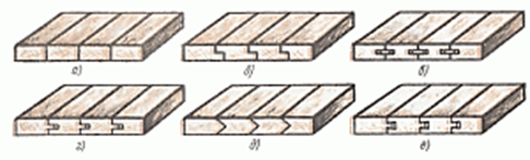
Connection of boards into shields: a - on a smooth fugue, b - in a quarter, c - on a rail, d - in a groove and a rectangular comb, e - in a groove and a triangular comb, e - in a dovetail
Also, when assembling the shields, dowels, tips in the groove and a comb with the rail pasted into the end are used. Among the glued rails, there are triangular, rectangular and glued ones, and when using the dowel, the dovetail groove is mainly chosen. All this is necessary for reliable fastening of the shield.

Shields: a - with dowels, 6 - with a tip in the groove and comb, c - with a glued rail in the end, d - with a glued triangular rail, e - with a glued triangular rail.
Length connection
Among the popular types of connections along the length can be distinguished: end-to-end, on the "mustache", in the groove and comb, on the toothed adhesive connection, in a quarter and on the rail. The most popular gear connection, because it has the best strength.

The connection of the bars along the length: a - end-to-end, b - in the groove and ridge, c - on the mustache, d, d - on the toothed adhesive connection, e - in a quarter, g - on the rail
There is also splicing, when longer segments are joined together. This can happen in several ways. For example, half a tree, oblique cut, oblique and straight overhead lock, oblique and straight tension lock and end-to-end. When choosing half-wood splicing, the required joint length should be 2 or 2.5 times the thickness of the timber. For greater reliability, dowels are used, for example, this can be found in the construction of cobbled houses.
When using an oblique cut with end trimming, the dimensions are 2.5 - 3 of the thickness of the beam and are also fastened with dowels.
The connection with a straight or oblique overhead lock is used in structures in which tensile forces are present. A straight overhead lock is located on a support, and an oblique one can be placed at the supports.
If you decide to use a bevel cut with end trimming, then the connection should have 2.5 or 3 bar thicknesses. In this case, the same dowels are used.
When docking with a straight or oblique tension lock, you don’t have to worry about strength, but such a connection is difficult to manufacture, and when the wood dries out, the wedges are weakened, so this connection method is not suitable for serious structures.
Butt splicing is when the two ends of the beam are placed on a support and securely connected with staples.

Splicing: a - half a tree, b - oblique cut, c - straight overhead lock, d - oblique overhead lock, d - straight tension lock, e - oblique tension lock, g - end-to-end
The connection of beams or logs can be found in the construction of walls or in the upper or lower trim in frame houses. The main types of compounds are half a tree, half-paw, spiked and corner frying pan.
A half-tree cut is considered to be a cutting or cutting of half the thickness at the ends of the bars, after which they are connected at an angle of 90 degrees.
The half-lap connection is formed when cutting at the ends of the bars of inclined planes, due to which the bars are tightly connected. The slope size is determined by the formula.
Cutting with a corner frying pan is very similar to cutting in half a tree, but the distinguishing feature is that with such a connection one of the bars loses a small part in width.
Building
The extension of beams and logs is the connection of elements in height, which is often used in the construction of poles or a match.
There are several types of extensions:
1) butt with a hidden spike;
2) end-to-end with a through comb;
3) half-wood with bolting;
4)half a tree with fastening with clamps;
5) half-tree with fastening with strip steel;
6) oblique cut with fastening with clamps;
7) butt with overlays;
8) bolting;
The length of the joints is usually 2-3 of the thickness of the joined beams or 2-3 of the diameter of the logs.

Connection of logs during extension: a - end-to-end with a hidden spike, b - end-to-end with a through ridge, c - half-tree with fastening with bolts, d - half-tree with fastening with strip steel, e - half-tree with fastening with clamps, e - oblique cut with fastening with clamps, g - end-to-end with overlays and fastening by bolts
spike connection
When spike knitting bars, a spike is cut on one, and an eye or nest is made on the other. Spike knitting of bars is often used to create joinery, doors, windows or transoms. All connections are made with glue. You can use not only one, but two or more spikes. The more spikes, the larger the bonding area. This type of connection can be divided into corner end, corner middle and corner box.
At the corner end connection, an open through spike is used (one, two or three), a spike with a dark through and blind, plug-in dowels. Angular middle connections can be found on the doors. Angled middle and end can additionally use nails, screws, dowels or bolts.

Corner spike connections: a - open through single spike UK-1, b - open through double spike UK-2, c - open through triple spike UK-3, d - blind spike with semi-darkness UK-4, e - through spike with semi-darkness UK-5, e - blind spike with darkness UK-6, g - through spike with darkness UK-7, h - connection blind and through on the dowels UK-8, and - on the mustache with plug-in round dowels UK-9, to - blind on the mustache with a plug-in flat stud UK-10, l - through on the mustache with a plug-in flat stud UK-11

Angled middle joints on the spike: a - blind type US-1, b through US-2, c - double through US-3, d - blind into the groove and crest US-4, e - blind into the groove US-5, e - blind on round dowels US-6
Timber products such as beams, boards or bars are mainly produced in a specific size, but often the construction may require material that has a greater length, width or thickness. For this reason, in order to achieve the required size, several types of connections are used using notches made by specialized equipment or manually by marking.
Width Connections
After fastening boards with a small width, they acquire a shield with the dimensions required for production. There are several methods for docking:
1)Docking on a smooth fugue;
in this docking method, any board or rail is referred to as a plot, and the formed seam is referred to as a fugue. Jointing can be considered of high quality only when there are no gaps between the joints of the edges of adjacent boards.
2)Rail fastening;
grooves are selected along the edges of the plot and slats are inserted into them, fastening the boards to each other. The thickness of the lath and the width of the groove itself cannot exceed 1/3 of the thickness of the timber used
3) Quarter fastening;
in joined plots, completely along the entire length, quarters are selected. With this method, quarters cannot exceed 50% of the thickness of the plot itself.
4) Docking type in a groove and a crest (rectangular and triangular);
this type of docking provides for the presence of a groove on one edge of the plot, and a ridge on the opposite edge, the shape of which can be either rectangular or triangular. At the same time, the latter is used infrequently, due to the lower level of the fortress. This kind of docking is quite in demand and is often used in the manufacture of parquet. Lack of bonding - lower cost savings due to using more boards
5) Fastening type "dovetail";
this type of docking is somewhat similar to the previous version, but only the crest here has a trapezoid shape, similar to the tail of swallows. Hence the name of the mounting method.
Connection of boards into shields: a - on a smooth fugue, b - in a quarter, c - on a rail, d - in a groove and a rectangular comb, e - in a groove and a triangular comb, e - in a dovetail.
Also, in the production of wood panels, dowels, a comb with a glued into the end rail and tips into the groove are often used. Laths for pasting can have a rectangular shape or triangular. When using keys, it is better to prefer a dovetail groove. All this is necessary for the manufacture of high-quality wood panels.
Shields: a - with dowels, 6 - with a tip in the groove and comb, c - with a glued rail in the end, d - with a glued triangular rail, e - with a glued triangular rail.
Length connection
The most popular methods of joining along the length are: close, such as a groove and a ridge, fastening with a “mustache”, a notched type of adhesive bonding, a quarter, and also a fastening on a rail. The most actively used docking is of the gear type, due to its extremely high level of strength.
 The connection of the bars along the length: a - end-to-end, b - in the groove and ridge, c - on the mustache, d, e - on the toothed adhesive connection, e - in a quarter, g - on the rail.
Also, the boards can be joined by splicing, when the timber segments are joined together in length. This is done in several ways. For example, in half a tree or a cut of an oblique type, an overhead lock of an oblique type and a straight one, close, as well as a tension lock of both a direct type and an oblique one. When splicing using the half-tree method, the required length must be 2-2.5 of the bar thickness indicator. To increase the level of reliability, dowels are used. For example, a similar option can be observed when building cottages from timber.
When using a cut of an oblique type with trimming the ends, the size should be equal to 2.5-3 of the thickness of the bar. It is also fixed with dowels.
Fastening with an overhead lock of an oblique or direct type is used in those structures where there is a tensile force. A straight type overhead lock is placed directly on the support itself, and an oblique type lock can be placed at the support.
If you have decided to use an oblique cut with trimming of the ends, then the bond must be 2.5-3 of the thickness of the bar. In such situations, dowels can also be used.
When fastened with a tension lock of an oblique or straight type, a high level of strength is achieved. But at the same time, such a docking is difficult to manufacture, and the wedges are somewhat weakened when the tree dries out. For these reasons, this fastening method is not suitable for structures that carry high loads.
Splicing closely implies the movement of both ends of the bar to the support and subsequent fastening with staples.
 Splicing: a - half-tree, b - oblique cut, c - straight overhead lock, d - oblique overhead lock, d - straight tension lock, e - oblique tension lock, g - end-to-end.
The fastening of logs or beams can be observed during the construction of the walls of frame houses, in the upper or lower part of the strapping. The key types of fasteners are: half-tree, corner frying pan, spike type and half-paw.
Docking in half a tree - direct cutting or cutting off 50% of the thickness at the edges of the bars, as well as their subsequent fastening at a right angle.
The half-leg joint is formed by cutting inclined planes at the edges of the bars, as a result of which a tight connection of the bars is obtained. The slope value must be determined by a special formula.
Cutting with a corner frying pan is very similar to cutting with a half-tree method, but differs from it in that with this type of fastening one of the bars loses a little in width.
The connection of the bars at an angle: a - half-tree, b - half-paw, c - spiked, d - angular.
Height connection
The cruciform fastening of the bars is often observed during the construction of bridge structures. With this option, you can use docking half a tree, a third and a quarter, and also a notch of only one of the bars.
Cross-shaped connection of the bars: a - half a tree, b - a third of a tree, c - a quarter of a tree, d - with a notch of one bar.
The method of building boards or bars in height is called fastening materials in height, which is very actively used in the construction of poles or masts.
Extension is divided into the following types:
- Close with a spike of a secret type.
- Close with a through-type comb.
- Half wood with bolt fastening.
- Half-tree with fastening on clamps.
- Half-wood with steel strip fastening.
- An oblique type cut with fastening on clamps.
- Close with overlays.
- Fastening with bolts.
The length of the joints themselves, as a rule, is equal to 2/3 of the thickness of the joined bars or 2/3 of the diameter of the logs.
Connection of logs during extension: a - end-to-end with a hidden spike, b - end-to-end with a through ridge, c - half-tree with fastening with bolts, d - half-tree with fastening with strip steel, e - half-tree with fastening with clamps, e - oblique cut with fastening with clamps, g - end-to-end with overlays and fastening by bolts.
spike connection
When the bars are fastened by means of spikes, a direct spike is cut on one of them, and an eye or a nest is made on the other. The knitting of beams with a spike method is actively used in the production of such joinery products as doors, windows or transoms. Each fastening is carried out on the basis of glue. It is allowed to use not only one spike, but several. The greater the number of spikes planned to be made, the larger the gluing area will be, respectively.
This type of docking is divided into: corner end type, corner middle type and corner box type.
For corner fastening of the end type, unclosed through spikes (no more than three), spikes with darkness of the through and non-through type, as well as a plug-in dowel are used. Docking angular median type is quite common on the doors. With corner fasteners of the middle and end type, you can additionally use screws, nails or bolts.
Angled middle joints on the spike: a - blind type US-1, b through US-2, c - double through US-3, d - blind into the groove and crest US-4, e - blind into the groove US-5, e - blind on round dowels US-6.
That's all the key information about the existing types of connections. This does not include connections with nails, screws or bolts. Pure wood well and a little bit of glue. 🙂
Joinery bars are interconnected by a spike joint, consisting of two elements - a spike and a socket or eye. Spike - a protrusion at the end of the bar, included in the corresponding

Rice. 42. Types of spikes:
a- single, b- double, in- multiple G- round, d- dovetail e- one-sided dovetail f, h- serrated and- nest, k, l- eyelets, m- deaf thorn n- thorn in the dark, about- spike in
semidarkness
vuyuschie nest or eyelet of another bar. The spikes are single (Fig. 42, a), double (Fig. 42.6), multiple (Fig. 42, c), that is, more than two.
A solid spike is a spike that is integral with the bar. A plug-in spike is a spike made separately from the bar. A spike with a cross section in the form of a circle is called round (Fig. 42, G).
The dovetail spike (Fig. 42.5) has a profile in the form of an isosceles trapezoid with a large base on the end face of the spike, a one-sided dovetail spike - in the form of a rectangular trapezoid with a large base on the end face of the spike (Fig. 42, e).
The toothed spike has a profile in the form of a triangle or trapezoid, the smaller base of which is the end face of the spike (Fig. 42, h), bi-oblique serrated spike (Fig. 42, g) of an isosceles triangle.
Single and double spikes are used in the manufacture of windows, frame doors, furniture; spike "dovetail" - in the manufacture of boxes, boxes; jagged spikes - for glued joining of parts (splicing) along the length.
In addition, round plug-in spikes are used when connecting plots (blanks) in width. Thorns in the dark and semi-darkness (Fig. 42, but), used in the manufacture of frames, me-

Rice. 43. The shape of the processed bars:
a- chamfer, b- headquarters (shtap), in- edge rounding G- fillet, d- fold-quarter, e- kalevka, well- thorn, h- eye, and- edge with profile processing, to- bar, l - nest, m- layout, n- plastic, about- overhang; / - shoulders, 2 - lateral edge of the spike, 3 - end face of the spike, 4 - panel, 5 - edge, b- butt, 7 - face; / - spike length, b- stud width, s - stud thickness
leucorrhea, etc. In addition, sockets and eyes are used, a deaf spike, shown in fig. 42, i, k, l, m.
A dark spike is made not only at the end connection, but also in cases where it is required that the edges of the nest be invisible, since it is not always possible to obtain even edges of the nest. To hide this defect, a darkness is cut out from the spike, that is, a part of the spike is removed along the width from one or both sides.
In order to form a spike, an eyelet, processed bars, i.e. planed from four sides to the required size, -f- pre-marked.
Structural parts and elements of joinery. Joinery products have the following main structural parts and elements.
Bar- the simplest detail; it happens in different sizes, sections and shapes (Fig. 43). The narrow longitudinal side of the bar is called the edge, and the wide longitudinal side is called the face, the line of intersection of the face with the edge is called the rib. The end transverse side of the bar, formed when trimming at a right angle, is called the end.
In the manufacture of window and door blocks, bars of small sections (vertical, horizontal sash sashes) are
they are made of solid wood, and bars of large sections (boxes) are made glued.
layouts are called bars intended for fastening glass in sashes, doors or panels in door leafs of a frame structure.
Panels are a rectangular shield made of carpentry, chipboard or fiberboard. The shape of the panels are flat, with beveled edges and with profiled edges. The panel within the doors is installed in a groove, rebate and fastened with layouts or placed on bars and fastened with screws.
folded called a rectangular recess in the bar. If the recess has equal sides of the angle, then it forms a quarter.
Platik- ledge formed to hide the gap; used in cases where fitting the part flush is difficult. The use of platik simplifies the assembly of products. It is used in the manufacture of furniture.
Overhang- protrusion beyond the base. Used in the manufacture of furniture.
Galtelyu called a semicircular recess on the edge or face of the part.
Frame consists of four bars forming a square or rectangle. Separate frames have, in addition, internal mullion bars (frame doors, window sashes with slabs).
The frames are assembled on a spiked joint. Small-sized frames are assembled on a single open through spike or spike with a semi-darkness or darkness. In the manufacture of joinery, mainly rectangular frames are used, very rarely (for unique buildings) - polygonal or round. A window sash, a window leaf, a transom, a box - all these are frames.
All connections in window blocks are made on spikes. The strength of a spiked joint is determined by its dimensions and the area of the bonded surfaces. To increase the strength, the spikes are made double (in the windows).
Shields are made massive (plank) or with voids. Massive shields in order to avoid warping should be assembled from narrow slats (parts) with a width of not more than 1.5 thickness, with the selection of fibers, humidity up to (10 ± 2)%.
When gluing parts along the width, the same (sapwood) faces of the joined rails should face in opposite directions, and the edges of the same name should face each other.
Joining rails along the length is allowed if the joints are spaced apart and the distance between them in adjacent rails is at least 150 mm. In panels designed for load-bearing structures, the rails do not join along the length. Wall panels, vestibules, etc. are made from shields.
To avoid warping, shields are made with dowels

Rice. 44. Types of shields:
a- with dowels b- with tips in the groove (tongue) and comb, in- with a glued rail at the end, G- with glued triangular rail, d- with a glued triangular rail, e-
multilayer
(rice. 44, a), with tips (Fig. 44.6), with glued and glued rails (Fig. 44, c, g,e). The dowels in the shields are made flush with the plane or protruding. At least two dowels are placed on each shield. Shields with dowels are designed for doors of temporary buildings, etc.
a) S) in)
Rice. 45. Methods for connecting shields:
a- for a smooth fugue, b- on the rail in- in a quarter G- in a groove and a comb, d- in a groove and a triangular comb, e- in dovetail

Rice. 46. Adhesive joints of bars, boards along the length:
a- end, b- on the "must", in- on a stepped "mustache", G- on a stepped "mustache" with blunting, d- jagged e- vertical gear, w - horizontal gear, h- jagged on the "mustache", and- stepped; c - bevel angle, L- the length of the "mustache" of the spike, t- connection pitch, 6 - bluntness, 5 - gap, AT- thickness, i- spike angle
In addition to boards, multilayer shields are made, glued together from three or five single-layer shields with mutually perpendicular direction of the fibers (Fig. 44, e).
Massive shields are glued onto a smooth fugue (Fig. 45, a), on a rail (Fig. 45.6), in a quarter (Fig. 45, c), in a groove and a crest (Fig. 45, d, e) willow "dovetail" (Fig. 45, e).
Connecting wood parts. Splicing of segments along the length can be end, on the "mustache", serrated, stepped (GOST 17161-79).
End glue connection(Fig. 46, a)- this is an adhesive connection with end surfaces of gluing. Under the end adhesive connection on the "mustache" (Fig. 46.6) is understood the adhesive connection with flat bonding surfaces located at an acute angle to the longitudinal axis of the workpieces. Adhesive connectionon a stepped "mustache"(Fig. 46, c) is a joint in which the bonding surfaces have a protrusion that prevents the workpieces from moving in the longitudinal direction during tension. A connection in which the beveled ends of the workpieces have a bluntness that prevents the displacement of the workpieces in the longitudinal direction during tension and compression is called a connection to a stepped "whisker" with a blunt (Fig. 46, G).
Serrated glue connection(Fig. 46, e)- this is a connection with profiled surfaces in the form of toothed spikes, twirlhot glue joint(Fig. 46, e)- connection with the output of the profile of the spikes on the face of the workpiece. In a horizontal gear connection (Fig. 46, g), the profile of the spikes goes to the edge of the workpiece.
Serrated adhesive connection on the "mustache"(Fig. 46, h)- connection
on the “mustache” with profiled bonding surfaces in the form of jagged spikes.
Step glued joint(Fig. 46, and)- end connection with profiled bonding surfaces in the form of a step, the height of which is equal to half the thickness of the workpiece.
The most durable is adhesive connection on a toothed spike. This type of connection is used for splicing bars of sashes, transoms, window and door frames and other building elements.
Serrated glue connection(see fig. 46, e) are manufactured in accordance with GOST 19414-90. The workpieces to be glued should not differ in moisture content by more than 6 %. Knots larger than 5 mm are not allowed in the workpiece joining area. The roughness parameter of the bonding surfaces of toothed spikes Rmax according to GOST 7016-82 should not exceed 200 microns.
The dimensions of the spiked joints are given in Table. one.
TableI. Stud sizes
Rallying consists in connecting bars, boards, plots along the width of the edge into shields or in layers into blocks. Each workpiece connected to the shield is called plot.
In accordance with GOST 9330-76, the connection along the edge is recommended, depending on the purpose of the products, to be made on a rail, in a quarter, in a rectangular and trapezoidal groove and comb, and on a smooth fugue.
When making connections to the K-1 rail (Fig. 47, a), it should be done at / equal to 20 ... 30 mm 1\ 2...3 mm more; S\ take equal to 0.4 So for wood laths and 0.25 5 0 - for plywood laths. The size S\ should be equal to the nearest dimensions of the slotted disc cutter, i.e. 4, 5, 6, 8, 10, 12, 16 and 20 mm. On the edges, one- and two-sided chamfers are allowed.
For a K-2 type connection along a quarter edge (Fig. 47, b):ho= 0.5 So - 0.5 mm, b is dependent on S 0 :
S 0 , mm I2...15 15...20 20...30 30
b, mm 6 8 10 16


Rice. 47. Connection diagrams of boards (plots) along the edge:
a- along the edge on the rail K-1, b- a quarter along the edge of K-2, in- in a rectangular groove and a crest along the edge of K-3, G- in a trapezoidal groove and a crest along the edge of K-5, d- on a smooth fugue K-6 (along the edge), e- along the edge into a rectangular groove and crest K-4
For connection type K-3 in the groove and tongue (Fig. 47, in) rounding radius G make 1 ... 2 mm, and the size 1\ - 1 ... 2 mm larger than / (Table 2). On the edges, one- and two-sided chamfers are allowed.
Table 2.K-3 connection dimensions, mm
|
S, | ||
Dimensions of connections K-4 (Fig. 47, e) are given in table. 3. Table 3K-4 connection dimensions, mm
|
Sa |
b | |||||
The dimensions of the grooves and ridges of the K-5 connection (Fig. 47, d) are determined according to Table. 4.
Table4. K-5 connection dimensions, mm
|
St |
I | |||
The seam formed when connecting plots is called fugue. Plots from which the shield is glued onto a smooth fugue type K-6 (Fig. 47, e) must have smooth and even edges forming a right angle with the plane (plate) along the entire length. If there are no gaps when connecting the plots, then their jointing (fitting) is done with high quality. Shields are glued together in clamps, wai-maxes, presses.
In addition to gluing, shields can be assembled from plots into round plug-in spikes, while the diameter of the spike should be 0.5 of the thickness of the plot, and the length should be 8 ... 10 diameters. The spikes are set in increments of 100 ... 150 mm.
The connection into a groove and a ridge, as well as into a quarter, is made by selecting along the entire length of the edge (plot) on one side of the groove or a quarter, and on the other, a ridge or a quarter. This compound is used in the manufacture of shields, laying plank floors, carpentry partitions, filing ceilings. A plain joint is more economical than a quarter or tongue and groove joint.
When connecting to a rail along the edges of the plots, grooves are selected into which wooden or plywood rails are inserted.


 in the configuration?")


