I haven't written anything here for a long time... Somehow everything didn't fit.
But finally, something was found that could really be interesting to someone else, besides the author.
Frankly, I thought about this topic for a long time ... I rummaged through everything that could be found on the Internet and only realizing that there was very little really sane and useful on the topic voiced in the title, I decided to crown my efforts with an epistolary report, for which, first all armed with a camera to capture the process in every detail, trying not to miss a single important moment.
So, I'll start, perhaps, from afar ..
It so happened that for more than 30 years of practice of my radio engineering "creativity", I have never had a chance to make a completely tube amplifier.
There were many reasons for this!
I will not list them all. Let me just say that I have dealt with lamps, and quite successfully and productively. But this was due to the pre-amplification cascades and made it possible not to get involved with hemorrhoids, due to the need to mount a bunch of pieces of iron, in the form of chokes, large trances and others like them.
But here I wanted, at least once in my life, to make a classic (moreover, it’s a classic !!!) lampovik, with lamps beautifully glowing in the dark, mounted outside ...
It’s not that I didn’t understand what it would result in for me ... But, to be honest, I didn’t realize that, unlike the design of semiconductor (“stone”) equipment, the manufacture of a tube apparatus should rather be attributed not so much to electronics as to locksmith work.
But I'm getting ahead of myself...
To begin with, as I said above, without further ado, I dug in the search engine line: "do-it-yourself tube amplifier."
However, having reached (no lie!!!) the tenth page of the search engine results, I realized that the main motive of those who had already managed to tell about their experience in creating tube amplifiers with their own hands was not the desire to teach others something, but rather the desire to show off their own achievements without sharing the secret of such "success" with others.
There is very little real information on HOW to do this, and if it is, it is very fragmented and stingy with details.
Actually, at that moment I realized that they favorably left me a place in this clearing. J
So, why, in fact, a lampovik?
I will not rant on the topic of fashion trends, such as Hi-End. It is clear that this is both fashionable and prestigious, and the tube sound, indeed, compares favorably with the transistor one. What? ... - This question is not here! If you only want to "decide for yourself" - raise the brain of your friends who have such devices, or managers in salons, such as the Purple Legion.
And if you decide that you want this, but to spend on this “miracle” of the money that those who sell it usually ask for this kind of equipment are not ready (and who cares, for what reason are you not ready! ..) then this article will probably be useful to you ...
So - where to start?
Perhaps, in this case, you can easily determine the sequence of actions!
In cases with "stone" devices, everything was somewhat different. First, the stuffing was assembled there, and only then did we think about cases for our creations.
In the case of tube amplifiers, everything is exactly the opposite, since for these machines the amplifier housing is, first of all, a structure that carries all the main elements. So, first of all, decide how you would like your amplifier to look as a result, that is, decide on the case!
I must say (I know from my own experience) that this is the most difficult issue in our "fatherland". Alas, in Rus', finding a decent case for radio equipment is an almost impossible task. L
I'm not that lucky ... But at one time I brought a lot of such iron from the "under heaven". Therefore, I was lucky to get past this problem. And I'll even say more! Perhaps I can help some of you deal with this problem! ;) Well, yes, it's all only privately...
In the meantime, having decided on how our creation should look, it is worth solving the second, of the most important tasks - deciding which one to assemble from amplifiers?
Schemes, ideas, not to mention opinions, just an incredible amount!
And it’s incredibly difficult to figure out on the go which of the ideas to grab on to.
In such cases, it is worth starting with the simplest and, at the same time, material that has been worked out not even for years - but for decades ...
But there is a lot of such, as the practice of studying the issue has shown.
And here, perhaps, it is worth starting to share your own experience.
There are a lot of established stereotypes in our minds. So, for example, high-speed car driving inevitably evokes associations with Michael Schumacher, and the racing car itself inevitably evokes the red Ferrari ...
Similarly, in a situation when it comes to tube Hi-End, the first thing that comes to mind for people who have already come into contact, at least to a minimal extent, with this topic is, of course, Audio Note.
For more than a dozen years, the Audionot sound has been almost like a religion among a large part of the “sophisticated high-end players”
At one time, many copies were broken in the field of discussions about what, in fact, is this secret of the sound of the creations of Peter Quartrup (dad and one of the main designers of Audio Note).
I remember that this chest was opened as easily as most of the others.
A relatively small number of experiments made it possible to find out that the main share of colors in the Audinot sound was made by the first cascade, usually built according to the so-called SRPP (cascade) scheme.
I didn’t philosophize either, having determined that it was he who should be at the entrance and nothing else, although something else could be simpler, but not much.
It's even easier with the output stage!
Here it is necessary to proceed from the principle of accessibility. Speaking of accessibility, I mean, first of all, the element base, on the basis of which you can build something quite worthy of sounding.
In this it is worth relying on the "experience of ancestors" that has come down to us in abundance in the form of the remains of old tube TVs and radiograms (Hello garbage dump!!!).
In extreme cases, this junk, in the form of weekend (TVZ-Sh) and power (TS-180) transformers, is usually in abundance at local flea markets, which take place on weekends in all regions and villages of our "immense" ...
And in conclusion, the problem of choosing an output lamp comes down to the understanding that these same TVZ-Sh output transformers were designed to work with almost the only lamp developed in the socialist fatherland, designed specifically to amplify sound. Of course, we are talking about the legendary 6P14P or its more modern counterparts 6P15P or 6P18P.
However, your choice! You can also supply a “branded” analogue in the form of EL 84. How much the result will be worth it is up to you to judge. Here I will only note that these replacements should not entail any structural or schematic changes. Even the modes of these lamps are almost identical and, most likely, you will not have to adjust anything with such a replacement on an already made and working amplifier.
Since we are talking about lamps, it is perhaps worth mentioning the light bulb for the first stage.
I'm not afraid of shields of malicious replicas of "dissenters", but IMHO there is simply no better candidate for the first cascade than 6N23P-EV. However, I will immediately warn you that the number of people who agree with me will be approximately equal to the number of those who objected. Let me just say that if we are striving specifically for the Audionot sound, then this is the very thing! J
Well, actually, we have almost drawn our own scheme.
To all of the above, it is worth adding, except that speaking about the output stage, I meant precisely and exclusively the 6P14P triode inclusion. It is in this inclusion that this lamp is able to touch the strings of the soul in a way that not many others.
Yes! This will result in a loss in power. But, perhaps, it was worth saying this earlier ... Hi-End is not for dubbing discos. Moreover! In Hi-End, the quality of the device is usually inversely proportional to the power (read sound volume) at which the amplifier reveals its full potential.
In addition, I will reassure you that the very 1.5 - 2 watts per channel that we can get with 6P14P in a triode connection, in terms of subjective sound volume, will seem adequate to 10 watts per channel, obtained from a typical silicon-transistor mustache.
So, just trust those thousands of people who have already walked this path before you and, believe me, were completely satisfied with the result. ;)
Moreover! I also have much more “serious” devices, which, of course, are objectively better than this creation. But this simple and, it would seem, completely uncomplicated machine has its own soul, gentle and kind ... Able to touch and warm people's souls with its very warm voice. J (Evan pulled me apart!.. Once again Sorry for the pretentious syllable.)
The only question of the circuitry of our wuxia, perhaps, was the question of "proper and healthy nutrition." And this, it must be said, is a matter of paramount importance when it comes to sound! For, the sound that we hear as a result, in fact, is nothing more than the power of your amplifier modulated by the input signal.
Hence the conclusion - the power supply of the tube amplifier must also be tube! So this is a kenotron! And if you absolutely remain adherents of the classics, then the throttle ...
And if everything is simple with a kenotron (by summing the anode currents of all the lamps, we get the total consumption, based on which the desired kenotron is selected), then with a choke, a problem can really arise ...
However, I was lucky. In my bins there was a real choke from some old tube TV. But even if not, then the simplest and most effective solution to this problem would be to buy a banal 18-watt choke for old fluorescent lamps at the nearest construction market for 120 wooden ones. Their 2 henry inductance (usually something like that...) is enough for our purposes.
How long - how short, but on the Runet spaces I managed to find two whole schemes that almost completely correspond to all the aspects voiced above. The first of them is built exactly according to the idea that was described by me above. The second one differs only in that it has a pair of output lamps in parallel at the output, but it has a beautifully painted power supply that fully meets all my requirements.
Here are the diagrams:
In fact, strange as it may seem, the essence of my article is not directly related to the amplifier circuit ... In any case, this is not the main thing for me in this case. The main thing is to tell about how to collect all this?
It is worth noting that the classic approach to building a tube amplifier, in contrast to transistor devices, usually assembled on printed circuit boards, is the assembly of the so-called surface mounting.
Frankly, for me this has always been the most repulsive factor in the issue of assembling tube circuits. For me, who is accustomed to making a separate printed circuit board even for a stand-alone volume changer, so that everything is correct and tidy, the very thought of parts freely dangling in the amplifier case, fastened together only by soldering and, sorry, hanging on snot, was frightening ... And , starting to build this machine, I had to overcome some internal barrier and practically invent on the go how to fix everything so that in the future I would not worry about that, and not that .... is there anything there at one fine moment ?. ..
Well, yes, everything is in order.
We take the case of our amplifier.
First, it is worth carefully diluting those commutations that we will need later. With your permission, I will omit this stage, since it is specific and does not imply many solutions.
I will just present the result as a given. In my case, it was the wiring of the input switch, ALPS for the volume control, and the actual input, output and power connectors themselves.
Characteristically, at this stage we remove the top and bottom panels of the case. The bottom panel just interferes with us, and we need the top panel as the basis of our design.
Here is what we have at this stage:
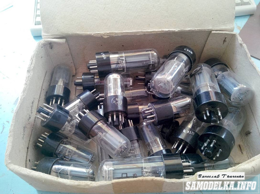
It seems that I missed one important point ... The fact is that before proceeding with the assembly of the amplifier, you must first select at least the main elements of the future machine. They are necessary in order to determine the design of your device.
This is primarily about light bulbs, sockets for them, output and power transformers and chokes. About the very elements that are attached directly to the body.
And only after fully picking up everything you need, we can arrange it the way you like it, determine the places for these elements and mark out the top panel.
Here is how I decided to arrange the elements of my amplifier:
I admit, I had an idea to plagiarize the topology of the arrangement of elements from one of the most popular Audio Note amplifiers, but, having overcome this temptation, I decided to arrange the elements according to the classical scheme. The idea of this topology, in this case, is not fundamental. The fact itself is important as a stage. This must be done very carefully, thinking about how convenient the chosen location will be for subsequent internal installation and about the mutual influence of the elements on each other.
This, of course, is about the magnetic fields of transformers and their orientation.
I suppose there is no need to present a short school physics course .. Just remember this. ;)
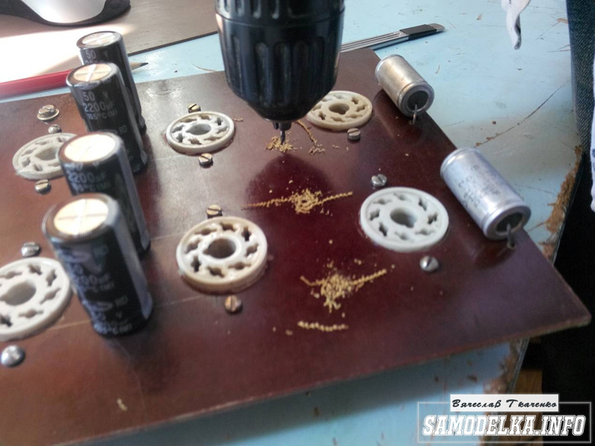
First of all, we place the panels for our lamps and determine the size of the holes for them:
Here we are in for another ambush and a silent question in our eyes: “And how to drill such HOLES in a sheet of iron?!”… In my case, it was exactly like that. And the answer to this question in the articles of "colleagues" who joyfully reported to me about how wonderful they assembled tube amplifiers with their own hands, I could not find.
I had to go to the nearest construction market and retrain from an electronics engineer to a locksmith.
I took the data with an ordinary caliper before going to the market. It turned out that the diameter of the holes for the sockets for finger lamps is 18 mm, and the diameter of the hole for the socket for the octal lamp (kenotron) is already 28 mm!
The study of the issue showed that for drilling holes with a diameter of 18 mm. you can find a classic drill, but for larger holes you will have to use a "crown" from "Bimetal".
Here's what it looks like:
Fortunately, I easily bought both of them on the construction market at 350 wooden ones per unit of goods.
JYou need to drill holes very carefully, and always from the side of the top panel, which will later be turned inside the case. I affirm this based on my own experience. Actually, an inquisitive eye will be able to see the consequences of my flaws in the photographs with which I accompany my story ...
Drill revolutions are the most minimal. In this case, if possible, it is worth using the auxiliary handle of the drill in order to stabilize the beating of the crown as much as possible.
Naturally, the edges of the holes obtained must be processed in order to remove the burrs that will inevitably remain after drilling the holes.
It turns out something like this:
To be continued…
Today we have a useful homemade product for connoisseurs of good sound: a high-quality do-it-yourself tube amplifier
Hello!
I decided to assemble a push-pull tube amplifier (my hands itch very much) from the parts that I have accumulated over a long long time: case, lamps, panels for them, transformers and so on.
I must say that I got all this stuff for free (tobish free of charge) and the cost of my new project will be 0.00 hryvnia, and if I need to buy something in small things, I’ll buy it for rubles (since I started my project in Ukraine, and I’ll finish already in Russia).
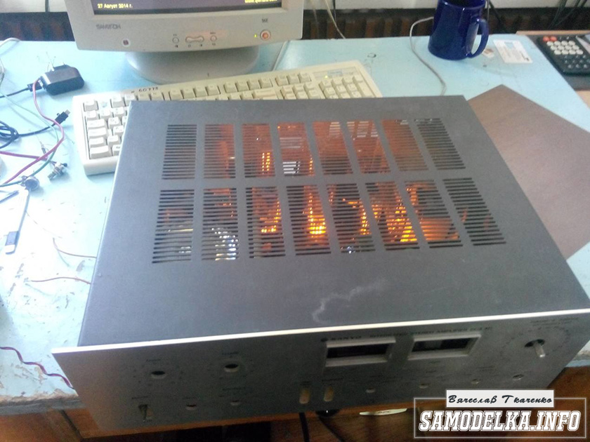
I'll start with the body.

Once upon a time it was, apparently, a good SANYO DCA 411 amplifier.
But I didn’t have a chance to listen to him, because I got it in a terrible dirty and non-working form, it was dug up to the point of being impossible and the burnt 110 V networker (Japanese, probably) smoked all the insides. Instead of native microcircuits of the final stage, some snot from Soviet transistors (this is a photo from the Internet of a good copy). In short, I gutted it all, and began to think. So, I didn’t come up with anything better than to shove a lampovik there (there is quite a lot of space there).

Decision is made. Now we need to decide on the scheme and details. I have enough lamps 6p3s and 6n9s.


Due to the fact that I already assembled a single-cycle 6p3s, I wanted more power and, after rummaging through the Internet, I chose this 6p3s push-pull amplifier circuit.
Diagram of a homemade tube amplifier (ULF)

The scheme is taken from the site heavil.ru
I must say that the scheme is probably not the best, but in view of its relative simplicity and availability of parts, I decided to dwell on it. Output transformer (an important figure in the plot).
It was decided to use the "legendary" TC-180 as output transformers. Do not throw stones right away (save them until the end of the article :)) I myself have deep doubts about such a decision, but given my desire not to spend a penny on this project, I will continue.

I connected the trance conclusions for my case like this.
(8)—(7)(6)—(5)(2)—(1)(1′)—(2′)(5′)—(6′)(7′)—(8′) primary
(10)—(9)(9′)—(10′) secondary
anode voltage is applied to the connection of terminals 1 and 1', 8 and 8' to the anodes of the lamps.
10 and 10′ per speaker. (I did not come up with this myself, I found it on the Internet). To dispel the fog of pessimism, I decided to check the frequency response of the transformer by eye. To do this, I assembled such a stand in haste.

In the photo, the GZ-102 generator, the BEAG APT-100 amplifier (100V-100W), the C1-65 oscilloscope, the load equivalent of 4 ohms (100W), and the transformer itself. By the way, the site has.
I set 1000 Hz with a swing of 80 (approximately) volts and fix the voltage on the oscilloscope screen (about 2 V). Then I increase the frequency and wait for the voltage on the secondary of the trance to begin to drop. I do the same in the direction of decreasing the frequency.
The result, I must say, pleased me. The frequency response is almost linear in the range from 30 Hz to 16 kHz, well, I thought it would be much worse. By the way, the BEAG APT-100 amplifier has a step-up transformer at the output and its frequency response may not be ideal either.
Now you can collect everything to the heap in the case with a clear conscience. There is an idea to make the installation and layout inside in the best traditions of the so-called modding (minimum wires in sight) and it would not be bad to make the backlight with LEDs as in industrial copies.
Power supply for a homemade tube amplifier.
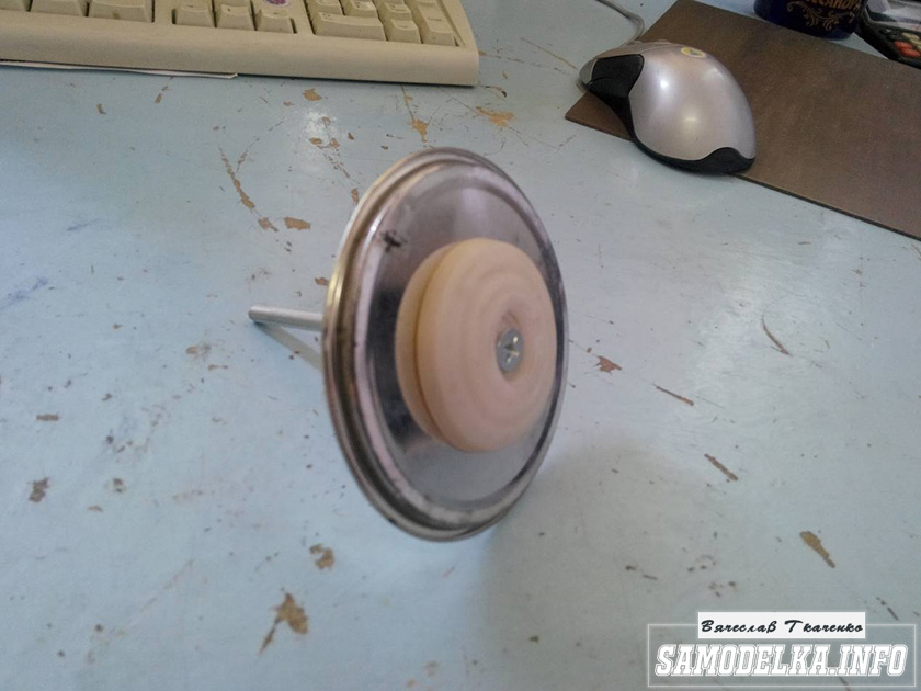
I will start the assembly with at the same time I will describe it. The heart of the power supply (and the entire amplifier, probably) will be the TST-143 toroidal transformer, which I at one time (4 years ago) tore with meat from some kind of tube generator right at the time it was being taken to a landfill. Unfortunately, I didn’t manage to do anything more. L, it’s a pity for such a generator, or maybe it was also a worker or it was possible to fix it ... Okay, I digress. Here he is my enforcer.


Of course, I found a diagram for it on the Internet.

The rectifier will be on a diode bridge with a filter on the inductor for anode power. And 12 volts to power the backlight and anode voltage. Throttle I have.

Its inductance was 5 henries (according to the device), which is quite enough for good filtering. And the diode bridge was found like this.

Its name is BR1010. (10 amps 1000 volts). I'm starting to cut out the amplifier. I think it will be something like this.

I mark and cut holes in the textolite for panels for light bulbs.

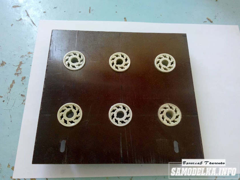


It turns out not bad :) so far I like everything.
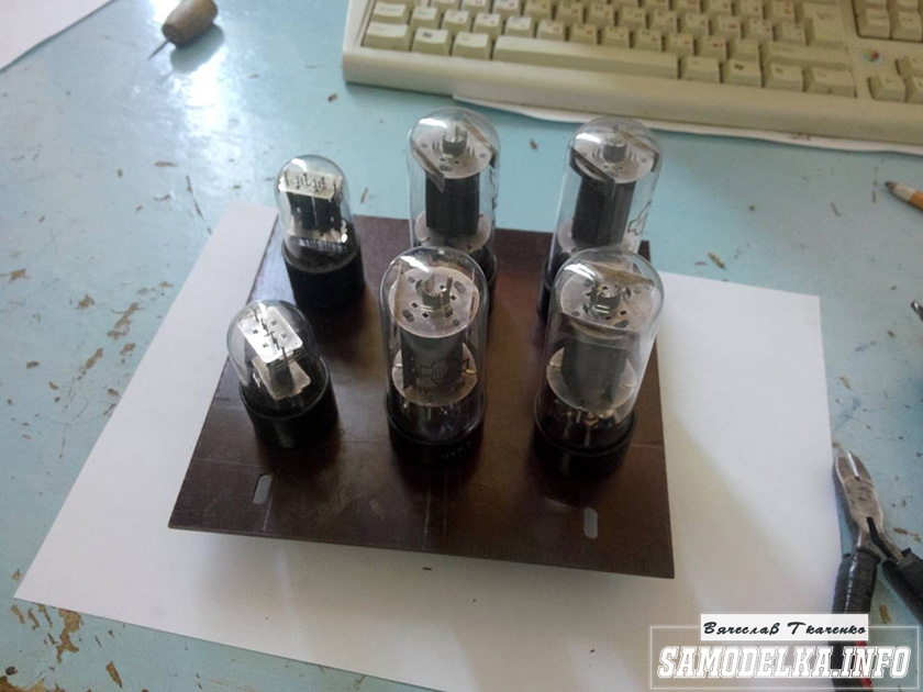
And so, and so. drilling sawing :)

Something began to emerge.

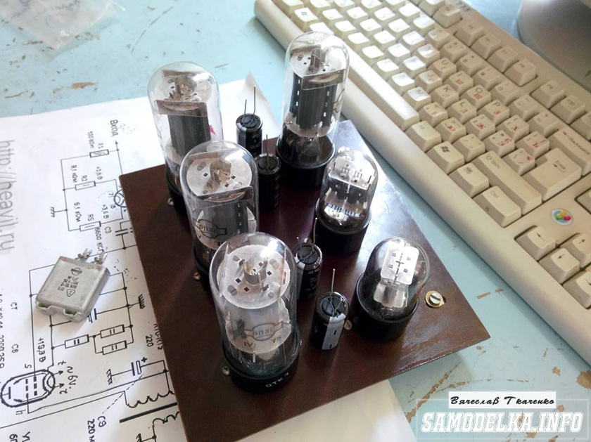
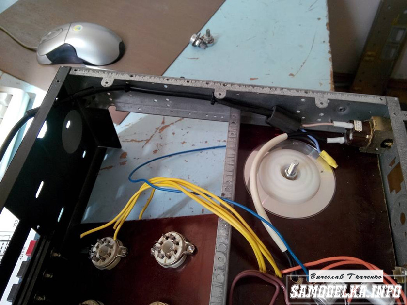
I found a fluoroplastic wire in old stocks and immediately all the alternatives and compromises regarding the wire for installation disappeared without a trace :).
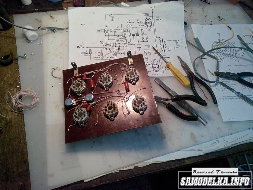

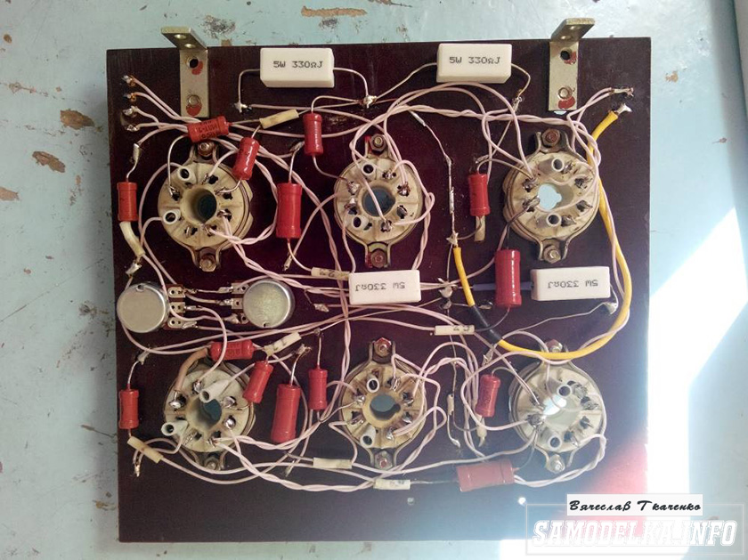
This is how the installation turned out. Everything is as if “kosher” the incandescences are intertwined, the earth is at one, practically, point. Should work.
It's time to fence food. After checking and checking all the output windings of the trance, I soldered all the necessary wires to it, and began to install it according to the accepted plan.

As you know, in our not easy anywhere without materials at hand: the container from the Kinder Surprise came in handy.

And a Nescafe lid and an old CD


I ripped out TV and monitor boards. All capacities are at least 400 volts (I know that I need more, but I don’t want to buy).

I shunt the bridge with containers (which ones were at hand, I’ll probably change them later)
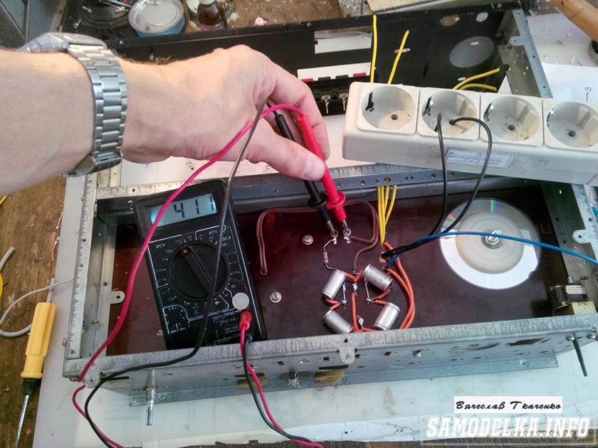
It turns out a bit too much, but oh well, it will sag under load :)
I use the regular power switch from the amplifier (clear and soft).

Done with this. Well done :)
Illumination for the body of the tube amplifier.
To implement the backlight, an LED strip was purchased.
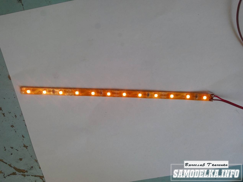
And installed as follows in the case.

Now the glow of the amplifier will be visible in the daytime. To power the backlight, I will make a separate rectifier with a stabilizer on some kind of KRKEN-like microcircuit (which I can find in the trash), from which I plan to power the anode voltage supply delay circuit.
Delay relay.
Digging through the bins of my homeland, I found just such a completely untouched thing.
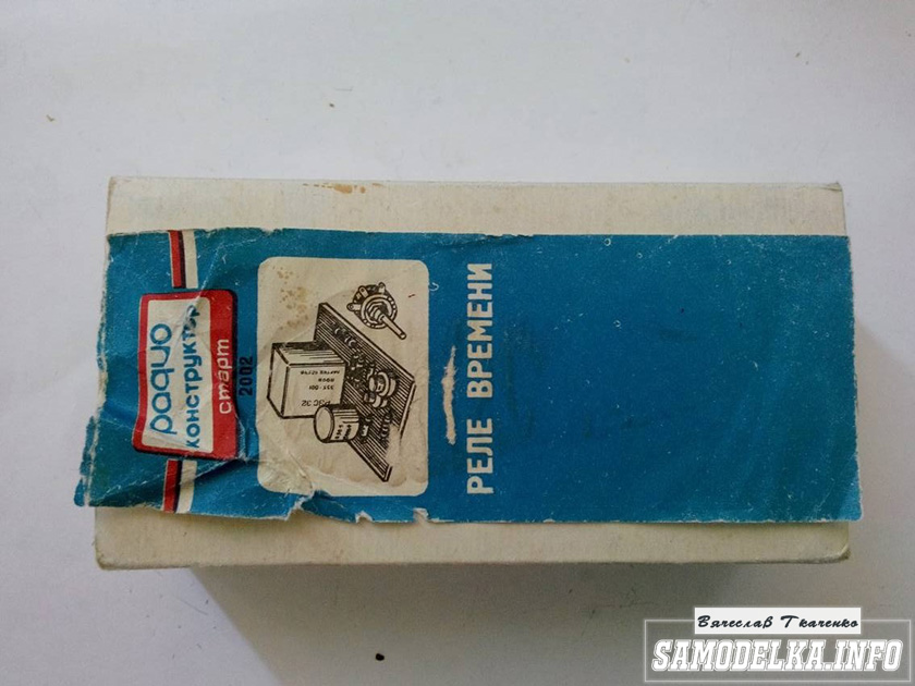
This is a radio time relay kit for a photo enlarger.
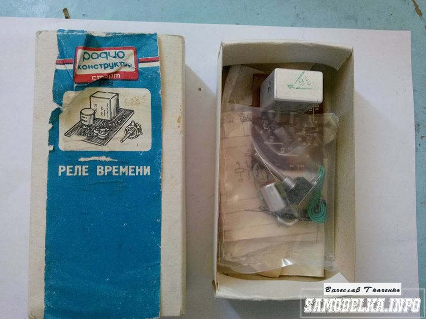
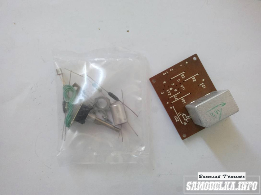
We collect, we check, we try on.
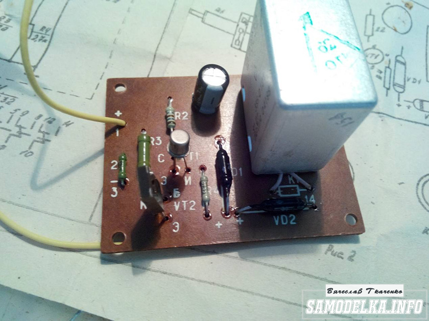
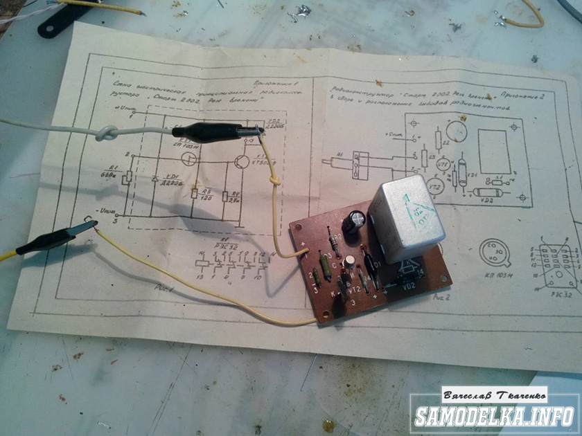
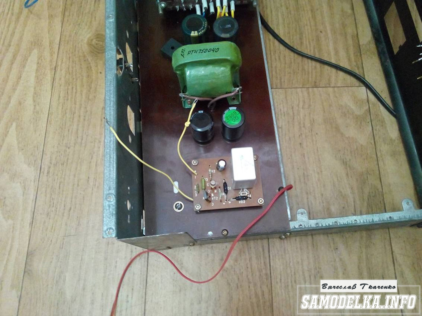
The response time was set to about 40 seconds, and the variable resistor was replaced by a constant one. The case is coming to an end. It remains to put everything together, put the muzzle, indicators and regulators.
Regulators (input variables)
They say that the sound quality can greatly depend on them. In short, I put these
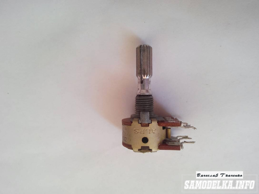
Dual 100 kOhm. since I have two of them, I decided to parallelize the conclusions, thereby obtaining 50 kOhm and increased resistance to wheezing :)
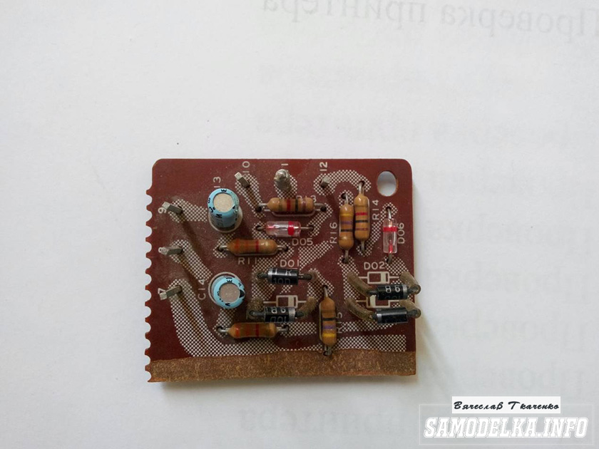
Indicators.
I used standard indicators, with standard illumination
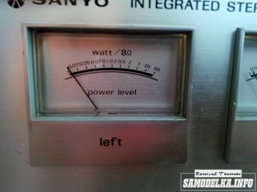
The connection diagram was mercilessly bitten by me from the native board and is also involved.
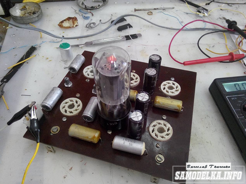
Here's what I ended up with.


When checking the power, the amplifier showed a voltage at the output of 10 volts of an undistorted sinusoid with a frequency of 1000 Hz to a load of 4 ohms (25 watts) equally across the channels, which pleased :)
When listening, the sound was crystal clear without background and dust, as they say, but too monitor, or what? nice but flat.
I naively thought that he would play without timbres, but ...
When using the software equalizer, we managed to get a very beautiful sound that everyone liked. Thank you all very much!!!
The author of the article "do-it-yourself home-made tube amplifier" Vyacheslav Tkachenko.
You may be interested in the following materials.
We have long been accustomed to the fact that we are surrounded everywhere by microelectronics, transistor technology. In TVs, players, receivers, tape recorders everywhere we hear the sound in the speakers amplified by special microcircuits, which are powered by low voltage and give a very loud sound.
But not so long ago - several decades, these very transistor amplifiers, and then microcircuits only appeared. Mods proudly wore receivers that were powered by special batteries - anode batteries and batteries for incandescent lamps, it was then just a miracle that you could receive and hear the radio on the go.
Lamps were very widespread. In cinemas, there were powerful tube amplifiers at the output of which two tubes G-807, 6R3S were usually used, less often GU-80.
And the famous mobile cinema installations "KINAP" of Odessa production for an alternating voltage of 110v, which were powered from a standard network through an autotransformer, at the output of the amplifier were the famous 6P3S lamps - lamps that were used in self-made medium-wave transmitters and it was a couple of trifles to make it, having still a tube receiver , a microphone and a wire antenna stretched in the yard, through which it was possible to communicate over the air with a friend from a neighboring street.
But time passed and new electronic devices appeared, which began to slowly replace the lamps, but it is still impossible to completely replace the lamps with transistors, because. lamps have an advantage in high-power output stages of transmitters, radar technology, but nevertheless the technical process is moving forward.
What attracts a tube amplifier?
The first and most important thing is the quality of the reproduced sound. The amplifier has primarily low distortion and high slew rate.
What is a good system? According to Alexander Chervyakov, “they put a record on and you can’t hear it, the better the amplifier, the less you hear it,” that is, you hear music, in the smallest subtleties, each instrument is music around you, you merged with it and nothing else exists, nervous.
Foot amplifier circuits
Construction scheme
According to the construction scheme, amplifiers can be divided:
1. First of all, single-cycle or push-pull - in the ULF output stage, one lamp or two lamps are used in the so-called push-pull switching. In the push-pull version, it is possible to get more power at the output, with good quality of the reproduced undistorted signal.
2. Mono amplifiers or stereo amplifiers.
3. Single-band or multi-band, when each amplifier reproduces its own frequency band and is loaded on the corresponding speaker system - speakers.
The amplifier consists of several sequential stages, as a rule:
- a preamplifier, sometimes called a microphone amplifier;
- amplification stage;
- repeater;
- phase inverter (for push-pull version);
- driver (for building up powerful output stages);
- output stage with a transformer in the load;
- load - acoustic system, sound speakers, headphones;
- power supply for different voltages: glow 6.3 (12.6), anode voltage 250v (300v and higher, depending on the lamps used in the output stage);
- case (metal chassis), since the transformer is heavy, and there are at least two of them in the circuit - power and output.
A diagram of a tube amplifier is given. Input amplifier on a pentode, lamp ECF80 (6BL8, 6F1P, 7199), triode 6AN8A, output stage on a beam tetrode KT88 or KT90 or EL156, kenotron 5U4G as a rectifier. Output transformer for Tanso XE205 single-ended tube amplifier. The power transformer in the anode winding has taps that switch depending on the applied output lamp.
Main specifications tube ULF, an example is shown in brackets - the parameters of the amplifier on the famous 300B lamp.
Power - W, at a load in ohms. (20)
Band of reproducible frequencies - Hz, kHz (5 -80 000)
Load resistance - Ohm (4-8)
Input sensitivity, mV (775)
Signal-to-noise ratio (no noise) dB (90)
THD, no more than % (less than 0.1 at a frequency of 1 kHz, at a power of 1 W)
Number of channels
Supply voltage, V
Power consumption from power supply - W (250)
Weight, kg
Overall dimensions, mm
Price
Components for manufacturing
Accessories for tube amplifier
Output transformer. One of the most important elements of high quality audio circuitry is the output transformer used. Applicable high quality output transformers for Hashimoto Audio, Tamura, Elektra-Print, Tribute, James Audio, Lundahl, Hirata Tango, AUDIO NOTE, etc.
Capacitors. To create the desired frequency response, the parameters of the component elements are important. Music lovers attach a very important role not only to the brands used, but also how they are included in the circuit: if the capacitor is between the stages of the amplifier, then the outer lining is connected to a lower impedance, i.e. to the driver, if as a blocking then the outer lining to the ground, in the picture the outer lining is marked with a stripe.


In the photo, capacitors for low-frequency sound amplifiers Jensen audio capacitors, aluminum, copper, silver are used as foil, respectively, the price varies widely. Audio line capacitor manufacturers: Audio Note, TFTF, Mundorf, Jensen, Duelund CAST and others. The frequency response varies depending on the performance: paper body - copper foil, copper body and copper overlays, frame - mylar in oil, aluminum foil in aluminum case and silver-plated leads, so high-quality sound fans take various measurements of the characteristics of parts to determine the best value for money - quality. Electrolytic capacitors have a wide range of choices: Black Gate, etc. For cathode circuits, Caddock is preferred.
Switches
Resistors. Various resistors are used for manufacturing: tantalum resistors Audio Note, metal film Beyschlag, Allen-Bradley, etc.
Lamps. Since we are talking about lovers of tube sound, one of the main elements for building is a lamp. Domestic lamps 6n2p, 6n8s, 6P3s, 6p14p, 6s33s, 6r3s. Fascinated by the perfect sound, true tube sound lovers prefer only NOS tubes - these are completely new tubes that were released a long time ago, for example, 6AC5GT, 45 tubes (the tube was produced from the late 1920s in the USA until the late 50s), 2A3 , 300V, etc. A large number of well-known lamps PX4, PX25, KT-88, KT-66, 6L6, EL-12, EL-156, EYY-12, 5692, ECC83, ECC88, EL34, 5881, 6SL7 have been used and are being used. But many prefer vintage lamps.
Manufacturers of electronic lamps.
German - Telefunken, Valvo, Siemens, Lorenz. Europe - Amperex, Philips, Mazda. England - Mullard, Genalex, Brimar. America - RCA, Raytheon, General Electrics, Sylvania and others. Amplifier tubes are purchased directly from abroad or through the websites www.tubes4audio.com, www.kogerer.ru, www.cryoset.com/catalog/index.php?cPath=22&osCsid=d721583766160686aa0fa118d03b88fd, www.groovetubes.com, www. iconaudio.com.
There are (manufactured) many quality amplifiers in the world.
Audio amplifiers load the speaker system, but there are many who sometimes want to listen to music on headphones, for example, MrSpeakers Alpha Dog.


On the picture. MB520 20W stereo amplifier, £950 and up, 15Hz~35kHz bandwidth, 82dB S/N ratio, 8/16 ohm load impedance, size 412x185x415 mm. EF86 preamplifier, 12AU7 lamp used as phase inverter, 5AR4 rectifier for each channel, EL34 output lamps. Stainless steel is used. Motor driven attenuator controlled by remote control, green LED indicates position.
The MB805 is a monoblock amplifier, £5,999. Power per channel (8 ohm load) 50W, signal-to-noise level is -90db.
MB81. Mono amplifier for GU-81, cost £12,500. The signal-to-noise ratio is -100dB, the ripple in the frequency band 20 Hz - 20 kHz is 1dB, the load is 4Ω - 16Ω. Input sensitivity 600mV, input impedance 100k. Power consumption from mains 220/240/115 volts average 450watts, 750w max. For a load of 8 ohms, the output is 200 watts. Input amplifier on a lamp 6SL7, 6SN7, drivers on two EL34.
SE (single-end) - single-ended output, which means signal amplification unchanged.
Video for lovers of tube sound
Eimac 250TH Audio Amplifier
Video of the operation of the tube amplifier with a demonstration of the playback of music playback.
People who love good music probably know about the Hi-End tube amplifier. You can make it yourself if you know how to use a soldering iron and have some knowledge of working with radio engineering.
Unique apparatus
Hi-End tube amplifiers are a special class of household appliances. What is it connected with? Firstly, they have a rather interesting design and architecture. In this model, a person can see everything that he needs. This makes the device truly unique. Secondly, the performance of the Hi-End tube amplifier differs from alternative models that use the Hi-End difference in that a minimum number of parts are used during installation. Also, when evaluating the sound of this unit, people trust their ears more than the harmonic distortion measurements and the oscilloscope.
Selection of circuits for assembly
The preamplifier is fairly easy to assemble. For it, you can choose any suitable scheme and start assembling. Another case is the output stage, that is, the power amplifier. As a rule, a lot of different questions arise with him. The output stage has several assembly types and operating modes.
The first type is the single-ended model, which is considered a standard cascade. When operating in the "A" mode, it has a small non-linear distortion, but, unfortunately, has a rather poor efficiency. Also note the average power output. If you need to fully sound a fairly large room, you will need to use a push-pull power amplifier. This model can work in the "AB" mode.
In a single-cycle circuit, only two parts are enough for a good operation of the device: a power amplifier and a preamplifier. The push-pull model already uses a phase-inverted amplifier or driver.
Of course, for two types of output stage, in order to work comfortably with, it is necessary to match the high interelectrode resistance and the low resistance of the device itself. This can be done with a transformer.
If you are a connoisseur of "tube" sound, then you should understand that you need to use a rectifier, which is produced on a kenotron, to achieve such a sound. In this case, semiconductor parts must not be used.
When developing a Hi-End tube amplifier, you can not use complex circuits. If you need to sound a fairly small room, then you can use a simple single-cycle design that is easier to make and set up.
DIY Hi-End tube amplifier
Before starting installation, you need to understand some rules for assembling such devices. We will need to apply the basic principle of mounting lamp fixtures - minimizing fixtures. What does it mean? You will need to discard the mounting wires. Of course, this cannot be done everywhere, but their number must be minimized.

In Hi-End, mounting petals and strips are used. They are used as additional points. Such an assembly is called hinged. You will also need to solder the resistors and capacitors that are on the lamp panels. It is strongly discouraged to use printed circuit boards and assemble conductors in such a way that parallel lines are obtained. Thus, the assembly will look chaotic.
Interference elimination
Later, you need to eliminate the low-frequency background, if, of course, it is present. Also important is the choice of grounding point. In this case, you can apply one of the options:
- The type of connection is a star, in which all "earth" conductors are connected to one point.
- The second way is laying a thick copper bus. It is necessary to solder the corresponding elements on it.
In general, it is better to find a grounding point yourself. This can be done by determining the level of low-frequency background by ear. To do this, you need to gradually close all the grids of lamps that are located on the ground. If, when the subsequent contact is closed, the low-frequency background level decreases, then you have found a suitable lamp. To achieve the desired result, it is necessary to experimentally eliminate unwanted frequencies. You also need to apply the following measures to improve the quality of your assembly:
- To make the filament circuits of radio tubes, you need to use twisted wire.
- The tubes that are used in the preamplifier must be covered with earthed caps.
- It is also necessary to ground cases with variable resistors.
If you want to power the preamp tubes, you can use direct current. Unfortunately, this requires the connection of an additional unit. The rectifier will violate the standards of a Hi-End tube amplifier, as it is a solid state device, which we will not use.
transformers
Another important point is the use of various transformers. As a rule, power and output are used, which must be connected perpendicularly. In this way, you can reduce the level of low-frequency background. Transformers should be located in earthed casings. It must be remembered that the cores of each of the transformers should also be grounded. It is not necessary to apply when you install devices, so that additional problems do not appear. Of course, these are not all the features associated with installation. There are quite a lot of them, and it will not be possible to consider them all. When installing a Hi-End (tube amplifier), you cannot use new element bases. They are now used to connect transistors and integrated circuits. But in our case, they do not fit.
Resistors
A high-quality Hi-End tube amplifier is a retro device. Of course, the details for its assembly must be appropriate. Instead of a resistor, a carbon and wire element may be suitable. If you spare no expense to develop this device, you should use precision resistors, which are quite expensive. Otherwise, MLT models are applicable. This is a pretty good item, as evidenced by the reviews.
Hi-end tube amplifiers are also applicable with BC resistors. They were made about 65 years ago. Finding such an element is quite simple, just take a walk around the radio market. If you use a resistor with a power of more than 4 watts, you need to choose enameled wire elements.
Capacitors
When installing a tube amplifier, you should use different types of capacitors for the system itself and the power supply. They are usually used for tone control. If you want to get high-quality and natural sound, you should use a decoupling capacitor. In this case, a small leakage current appears, which allows you to change the operating point of the lamp.

This type of capacitor is connected to the anode circuit, through which a large voltage flows. In this case, it is necessary to connect a capacitor that supports a voltage of more than 350 volts. If you want to use quality elements, you need to use Jensen parts. They differ from analogues in that their price exceeds 3,000 rubles, and the price of the highest quality radio elements reaches 10,000 rubles. If you use domestic elements, it is better to choose between the K73-16 and K40U-9 models.
Single Ended Amplifier
If you want to apply a one-cycle model, you must first consider its circuit. It includes several components:
- power unit;
- final cascade;
- a pre-amplifier in which you can adjust the tone.
Assembly
Let's start with the pre-amplifier. Its installation takes place according to a fairly simple scheme. It is also necessary to provide for power control and a separator for tone control. It must be tuned to low and high frequencies. To increase the shelf life, you need to apply a multi-band equalizer.

In the laughter of the pre-amplifier, one can see similarities with the common 6N3P double triode. The element we need can be assembled in a similar way, but using the final cascade. This is also repeated in stereo. Remember that the design must be assembled on a circuit board. First it needs to be debugged, and then it can be installed on the chassis. If you installed everything correctly, the device should turn on immediately. The next step is to move on to the settings. The value of the anode voltage for different types of lamps will be different, so you will need to select it yourself.
Components
If you do not want to use a high-quality capacitor, then you can use K73-16. It is suitable if the operating voltage is more than 350 volts. But the sound quality will be noticeably worse. Electrolytic capacitors are also suitable for this voltage. You need to connect an S1-65 oscilloscope to the amplifier and apply a signal that will pass from the audio frequency generator. At the initial connection, you need to set the input signal to about 10 mV. If you need to know the gain, you will need to use the output voltage. To find the average ratio between low and high frequencies, it is necessary to choose the capacitance of the capacitor.
You can see a photo of the Hi-End tube amplifier below. For this model, 2 lamps with an octal base were used. A double triode is connected to the input, which is connected in parallel. The final stage for this model is assembled on a 6P13S beam tetrode. A triode is mounted in this element, which allows you to get a good sound.

To set up and check the performance of the assembled device, you must use a multimeter. If you want to get more accurate values, then you should use a sound generator with an oscilloscope. When you have taken the appropriate devices, you can proceed to the setting. On the cathode L1 we indicate a voltage of about 1.4 volts, this can be done if you use the resistor R3. The output lamp current must be specified as 60 mA. To make a resistor R8, you need to install a pair of MLT-2 resistors in parallel. Other resistors can be of different types. It should be noted a rather important component - a decoupling capacitor C3. It was not in vain mentioned, since this capacitor has a strong influence on the sound of the device. Therefore, it is better to use a proprietary radio element. The other elements of C5 and C6 are film capacitors. They allow you to increase the quality of transmission of various frequencies.

A power supply built on a 5Ts3S kenotron is worth finding. It complies with all the rules for constructing the device. A homemade Hi-End tube power amplifier will have high-quality sound if you find this item. Of course, otherwise it is worth looking for an alternative. In this case you can use 2 diodes.
For a Hi-End tube amplifier, you can use the appropriate transformer, which was used in old tube technology.

Conclusion
To make a Hi-End tube amplifier with your own hands, you must perform all the steps consistently and accurately. First, connect the power supply with an amplifier. If you set up these devices correctly, you can mount a preamplifier. Also, using the appropriate technique, you can check all the elements in order to prevent breakage. After assembling all the elements together, you can begin to design the device. Plywood might work well for the body. To create a standard model, it is necessary to place radio tubes and transformers on top, and regulators can already be mounted on the front wall. With them, you can amplify the tone and see the power indicator.
So, I decided to try my hand at lamp technology. I found the necessary details and assembled the circuit on 6p14p and 6n23p lamps, at first just on a piece of iron. The output turned out to be 5 watts, the sound is loud and clear, nothing rings or cuts off. Satisfied with such ULF completely. It is powered by a transformer, which was taken from the Sirius radiogram. One 6 volt filament winding is involved, and 250 volts to power the anodes of the lamps. Although it has now become fashionable to install so-called "electronic transformers" in tube amplifiers, for beginner lamp builders I advise you to choose ordinary ones on iron.As a rectifier - a diode bridge, and as filters - 2 capacitors from a computer power supply, connected in series for 200 volts 470 microfarads, the result is an output of 315 volts on the capacitors. The whole thing is positively connected through a 2.7 kΩ resistor in the power gap. The anodes are powered by approximately 250 volts DC. We shunt the power filter capacitors with a 200 kOhm resistor so that there is something to discharge them after the device is turned off from the network.

The PSU is made in a separate case from the old tube TV. The tube amplifier itself is made in a case from a Soviet radio tape recorder, its case is thick and fits just right in size.

Sockets for lamps can be picked out from any lamp technology - they are all standard. We make a large hole with the help of small ones drilled in a circle. We clean the edges with a round file.

I made a speaker based on a 5-gd paper speaker, with a nominal power of 5 watts, the base itself is made of board, the back is plywood, and the speaker on the front panel is mounted on two pressed cardboard sheets.

I made the legs for all the blocks by gluing pieces of double-sided tape to the case so that they would not scratch the surface of the table. See the video about assembling a simple ULF on lamps below:
A 3.5 mm metal plug is soldered to the input, of the "mother" type. The conductor that is connected to the audio input must be well shielded.

I removed the volume control, since it only gives extra noise, and in the sound source itself (in my case, a DVD player), it is much more convenient to adjust it from the remote control!

Do not forget to put a 200-500 kΩ resistor on the input at the ground, and if you are making a regulator, then use a high-resistance one, I tried it at 1 mΩ and it turned out to be the best with it.

Perhaps the design will not seem very serious to someone, but please note that this is my first step in mastering tube ULFs. The next amplifiers will be more impressive. Comrade was with you. Redmoon.
Discuss the article SIMPLE TUBE AMPLIFIER


")


