In the case of transverse bending in the sections of the beam, not only a bending moment arises, but also a transverse force. Consequently, in this case, not only normal, but also tangential stresses arise in the cross sections of the beam.
Since the tangential stresses are generally unevenly distributed over the cross section, then, strictly speaking, the cross sections of the beam do not remain flat during transverse bending. However, at (where h- cross section height, l is the length of the beam) it turns out that these distortions do not noticeably affect the work of the beam in bending. In this case, the hypothesis of flat sections is also acceptable with sufficient accuracy in the case of pure bending. Therefore, the same formula (6.4) is used to calculate the normal stresses s.
Consider the derivation of calculation formulas for shear stresses. Let us single out from the bar experiencing transverse bending an element with a length dx(Fig. 6.6 A).

| A |
| b |
| V |
| G |
| A * |

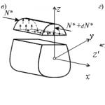
Longitudinal horizontal section drawn at a distance z from the neutral axis, we divide the element into two parts (Fig. 6.6 V) and consider the equilibrium of the upper part, which has a base of width b. At the same time, taking into account the law of pairing of tangential stresses, we obtain that the tangential stresses in the cross section are equal to the tangential stresses arising in the longitudinal sections (Fig. 6.6 b). Taking into account this circumstance and from the assumption that shear stresses over the area b× dx are uniformly distributed, using the condition åx = 0, we obtain:
N * - N * - d N* + t× b× dx = 0 ,
 . (6.5)
Where N* - resultant of normal forces s× dA in the left cross section
element dx within the area A* (Fig. 6.6 G):
 . (6.6)
Taking into account (6.4), the last expression can be represented as
 , (6.7)
Where  - static moment of the part of the cross section located above the coordinate y(in Fig. 6.6 b this area is shaded).
Therefore, (6.7) can be rewritten as  , where
 . (6.8)
As a result of joint consideration of (6.7) and (6.8), we obtain
 ,
,
or finally
 . (6.9)
Formula (6.9) is named after the Russian scientist D.I. Zhuravsky.
To study the stress state at an arbitrary point of a beam experiencing transverse bending, we select an elementary prism from the composition of the beam around the point under study (Fig. 6.6 G), so that the vertical platform is part of the cross section of the beam, and the inclined platform makes an arbitrary angle a relative to the horizon. We accept that the selected element has the following dimensions along the coordinate axes: along the longitudinal axis - dx, i.e. along the axis x; along the vertical axis - dz, i.e. along the axis z; along the axis y- equal to the width of the beam.
Since the vertical area of the selected element belongs to the cross section of the beam experiencing transverse bending, the normal stresses s on this site are determined by formula (6.4), and shear stresses t- according to the formula D.I. Zhuravsky (6.9). Taking into account the law of pairing of shear stresses, it is easy to establish that shear stresses on a horizontal platform are also equal t. The normal stresses on this site are equal to zero, according to the hypothesis of the bending theory already known to us that the longitudinal layers do not exert pressure on each other.
Let us denote the values of normal and shear stresses on the inclined area through s a And ta, respectively. Taking the area of the incline dA, for vertical and horizontal platforms we will have dA sin a and dA cos a respectively.
Composing the equilibrium equations for an elementary cut prism (Fig. 6.6 G), we get:

 ,
,
from where we will have:
Therefore, the final expressions for stresses on an inclined platform take the form:

Let us determine the orientation of the site, i.e. value a = a 0 , at which the voltage s a takes on an extreme value. According to the rule for determining the extrema of functions from mathematical analysis, we take the derivative of the function s a from a and equate it to zero:
 .
.
Assuming a = a 0 , we get:  .
.
From where we will finally have:  .
.
According to the last expression, extreme stresses arise on two mutually perpendicular areas, called main, and the stresses themselves - principal stresses.
Comparing the expressions t a and  , we have:
  , whence it follows that the tangential stresses on the main areas are always equal to zero.
In conclusion, taking into account the well-known trigonometric identities:

and formulas  , we determine the principal stresses, expressing from in terms of s and t.
We have seen that in pure bending, only normal stresses arise in the cross sections of the rod. The corresponding internal forces are reduced to a bending moment in the section. In the case of transverse bending in the section of the rod, not only a bending moment arises, but also a transverse force. This force is the resultant of elementary distributed forces lying in the section plane (Fig. 4.23). Consequently, in this case, not only normal, but also shear stresses arise in the cross sections.

The occurrence of tangential stresses is accompanied by the appearance of angular deformations. Therefore, in addition to the basic displacements inherent in pure bending, each elementary area of the section receives some additional angular displacements due to shear. Shear stresses are unevenly distributed over the section, so angular displacements will also be unevenly distributed. This means that in case of transverse bending, in contrast to pure izpb a, the cross sections do not remain flat. On fig. 4.24 shows a typical picture of the curvature of the cross sections.


However, the distortion of the plane of cross sections does not noticeably affect the value of normal stresses. In particular, if the transverse force does not change along the length of the rod, formulas (4.6) and (4.8), derived for the case of pure bending, will give completely accurate results in the case of transverse bending. Indeed, when the curvature of all sections occurs in the same way (Fig. 4.25). Therefore, with mutual rotation of two adjacent sections, the elongation of the longitudinal fiber AB will be the same, regardless of whether the section remains flat or not.
With a transverse force varying along the rod axis, the pure bending formulas give some error for a. By a simple analysis, it can be shown that this error is of the order of magnitude compared to unity, where is the size of the cross section in the bending plane; - rod length. According to the definition given in § B2, a characteristic feature of a rod is that its cross-sectional dimensions are much less than its length. Consequently, the ratio is relatively small and the specified error turns out to be correspondingly small.
All of the above gives reason to accept the hypothesis of flat sections. We will further assume that the set of points that form the plane of the cross section before bending also forms a plane rotated in space after bending. This assumption is acceptable to the extent that the angular deformations 7 in the section can be considered significantly smaller than the angular displacements due to the change in curvature.
A feature of transverse bending is also the presence of normal stresses arising in the longitudinal sections of the beam, i.e. stresses between layers. These stresses arise only with a variable transverse force and are very small.
Thus, within the indicated assumptions, formulas (4.6) and (4.8), derived for determining normal stresses, are applicable not only for pure bending, but also for transverse bending. Equally applicable is formula (4.5), which gives the dependence of the curvature of the rod on the bending moment.
Now let us determine approximately the tangential stresses in transverse bending. The easiest way to calculate these stresses is through the paired shear stresses arising in the longitudinal sections of the rod. Let's select an element of length from the beam (Fig. 4.26, a). In case of transverse bending, the moments arising in the left and right sections of the element are not the same and differ in the longitudinal horizontal section drawn at a distance y from the neutral layer (Fig. 4.26, b), we divide the element into two parts and consider the equilibrium conditions of the upper part. The resultant of the normal forces in the left section within the shaded area is, obviously,

or, according to formula (4.6),


where, unlike y, denotes the current ordinate of the site (see Fig. 4.26, b). The resulting integral is the static moment about the x-axis of the part of the area located above the longitudinal section (above the level Let us denote this static moment by Then

In the right section, the normal force will be different:

The difference between these forces

must be balanced by tangential forces arising in the longitudinal section of the element (see Fig. 4.26, b and c).
As a first approximation, we assume that shear stresses are uniformly distributed over the width of the section. Then
![]()
The resulting formula is called the Zhuravsky formula, after the Russian scientist of the last century, who was the first to conduct a general study of shear stresses in transverse bending.
Expression (4.12) allows one to calculate shear stresses arising in the longitudinal sections of the rod. The stresses formed in the cross sections of the rod are equal to them, as a pair. The dependence on y in the section is determined through the static moment 5. When approaching the upper edge of the section, the area of its shaded part (see Fig. 4.26, b) decreases to zero. Here, therefore, when approaching the lower edge, the shaded part covers the entire section. Since the axis is central, then here too. Therefore, the shear stresses, as follows from formula (4.12), at the upper and lower points of the section are equal to zero.

For a rectangular rod with sides and (Fig. 4.27, a) we have
Hence,

and the diagram of tangential stresses along the height of the section is represented by a square parabola. The greatest stress occurs at
![]()
For a circular rod (Fig. 4.27, b), by a simple integration operation, you can find

Besides,
![]()
![]()
For a rod having a section in the form of a triangle with a base c and a height (Fig. 4.27, c),

The maximum stress occurs at a distance from the neutral axis:
![]()
The last two examples clearly demonstrate the approximate nature of the operations performed. This can be seen from the fact that in the cross section, shear stresses have components not only along the y axis, but also along the x axis. Indeed, let us assume, as was done above, that for points A located near the contour of the section (Fig. 4.28), the shear stress is directed along the y axis. Let us decompose the vector into two components - along the normal to the contour and along the tangent. According to the loading conditions, the outer surface of the rod is free from tangential forces. Therefore, there are no voltage pairs. Therefore, while the total shear stress near the contour is directed tangentially to the contour, and the assumption that it is directed along the y axis turns out to be incorrect. Thus, the presence of components along the x-axis is detected. To determine these components, one should resort to more complex methods than


reviewed earlier. Using the methods of the theory of elasticity, it can be shown that in most cases the components along the x-axis play a significantly smaller role than along the y-axis.
From the examples considered above, we can make a general conclusion that the zone of maximum shear stresses is located approximately in the middle part of the section height, and for non-thin-walled sections it has a value of the order
It is possible to compare the absolute values of the maximum normal and maximum shear stresses arising in the cross sections of the rod. For example, for a rectangular console (Fig. 4.29) we have

This means that the maximum shear stresses in the cross section are related to the maximum normal stresses approximately as the height of the section is related to the length of the rod, i.e. shear stresses are significantly less than normal. The specified estimate, with a few exceptions, is preserved for all non-thin-walled bars. As for thin-walled rods, this is a special issue.
Due to the smallness of τmax, the calculation for strength in transverse bending is performed only for normal stresses, as in pure bending. Shear stresses are not taken into account. This is all the more natural because at the points of the section that are farthest from the neutral line, i.e. in the most dangerous, shear stresses in the cross section are zero.
Considering the qualitative side of the phenomenon, it should be borne in mind that shear stresses in cross sections and their paired stresses in longitudinal sections, despite their smallness, can in some cases significantly affect the assessment of the strength of the rod. For example, when transversely bending a short wooden beam, destruction is possible not along the cross section in the embedment, but shearing along the longitudinal plane close to the neutral layer, i.e. where shear stresses are maximum (Fig. 4.30).

Shear stresses in longitudinal sections are an expression of the existing connection between the layers of the rod during transverse bending. If this connection is broken in some layers, the nature of the bending of the rod changes. For example, in a rod made up of sheets (Fig. 4.31, a), each sheet bends independently in the absence of friction forces. The external force on the sheet is equal to and the greatest normal stress in the cross section of the sheet is equal to
In the case of transverse bending in the sections of the beam, not only a bending moment occurs, but also a transverse force. Consequently, in this case, not only normal, but also tangential stresses arise in the cross sections of the beam.
Since the tangential stresses are generally unevenly distributed over the cross section, then, strictly speaking, the cross sections of the beam do not remain flat during transverse bending. However, at (where h- cross section height, l- the length of the beam) it turns out that these distortions do not noticeably affect the work of the beam in bending. In this case, the hypothesis of flat sections is also acceptable with sufficient accuracy in the case of pure bending. Therefore, the same formula (5) is used to calculate normal stresses.
Consider the derivation of calculation formulas for shear stresses. Let's single out from a bar experiencing transverse bending an element with a length (Fig. 6.28, A).
Rice. 6.28
With a longitudinal horizontal section drawn at a distance y from the neutral axis, we divide the element into two parts (Fig. 6.28, V) and consider the equilibrium of the upper part, which has a base of width b. At the same time, taking into account the law of pairing of tangential stresses, we obtain that the tangential stresses in the cross section are equal to the tangential stresses arising in the longitudinal sections (Fig. 6.28, b). Taking into account this circumstance and from the assumption that shear stresses are uniformly distributed over the area, using the condition , we obtain:
where is the resultant of normal forces in the left cross section of the element within the shaded area:
Taking into account (5), the last expression can be represented as
where is the static moment of the part of the cross section located above the y coordinate (in Fig. 6.28, b this area is shaded). Therefore, (15) can be rewritten as
As a result of joint consideration of (13) and (16), we obtain
or finally
The resulting formula (17) is named after the Russian scientist DI. Zhuravsky.
Strength condition for shear stresses:
where is the maximum value of the transverse force in the section; - allowable shear stress, it is usually equal to half.
To study the stress state at an arbitrary point of a beam experiencing transverse bending, we select an elementary prism from the composition of the beam around the point under study (Fig. 6.28, G), so that the vertical platform is part of the cross section of the beam, and the inclined platform makes an arbitrary angle relative to the horizon. We accept that the selected element has the following dimensions along the coordinate axes: along the longitudinal axis - dz, i.e. along the axis z; along the vertical axis - dy, i.e. along the axis at; along the axis X- equal to the width of the beam.
Since the vertical area of the selected element belongs to the cross section of the beam experiencing transverse bending, the normal stresses on this area are determined by formula (5), and the shear stresses are determined by the D.I. Zhuravsky (17). Taking into account the law of pairing of shear stresses, it is easy to establish that shear stresses on a horizontal platform are also equal. The normal stresses on this site are equal to zero, according to the hypothesis of the bending theory already known to us that the longitudinal layers do not exert pressure on each other.
Let us denote the values of normal and tangential stresses on the inclined area through and , respectively. Taking the area of the inclined platform , for the vertical and horizontal platforms we will have and , respectively.
Composing the equilibrium equations for an elementary cut prism (Fig. 6.28, G), we get:
from where we will have:
Therefore, the final expressions for stresses on an inclined platform take the form:
Let us determine the orientation of the site, i.e. the value at which the voltage reaches its extreme value. According to the rule for determining the extrema of functions from mathematical analysis, we take the derivative of the function from and equate it to zero:
Assuming we get:
From where we will finally have:
According to the last expression, extreme stresses arise on two mutually perpendicular areas, called main , and the stresses themselves - main stresses.
Comparing the expressions and , we have:
whence it follows that the tangential stresses on the main areas are always equal to zero.
In conclusion, taking into account the well-known trigonometric identities:
and formulas,
we determine the principal stresses, expressing from through and:
We cut out from the beam in the vicinity of a certain point an elementary parallelepiped 1-2-3-4 (Fig. 45.7, a) whose side faces 1-2 and 3-4 are located in the cross sections of the beam, and the side faces 2-3 and 1-4 are parallel neutral layer. The length of the box (in the direction perpendicular to the drawing) is equal to the width of the beam. The stresses acting on the faces of the parallelepiped are considered in § 7.7 and 8.7; they are shown in fig. 45.7b. On faces 1-2 and 3-4, normal stresses a and tangential stresses act, and on faces 2-3 and 1-4, only tangential stresses act. The directions of these voltages, shown in fig. 45.7, b, correspond to the case when positive bending moment and transverse force act in the cross sections of the beam section under consideration.

The stress values are determined by formulas (17.7) and (28.7).
The front and back faces of the elementary parallelepiped coincide with the side surfaces of the beam, free from the load, and therefore the stresses on these faces are zero. Consequently, the parallelepiped is in a plane stress state.
In areas inclined at different angles to the side faces of an elementary parallelepiped, normal and tangential stresses act, the values of which can be determined by formulas (6.3) and (7.3). There are two mutually perpendicular areas along which shear stresses are equal to zero. These areas, as is known, are called the main areas, and the normal stresses acting in them are called the main stresses (see § 3.3). In areas inclined at angles of 45° to the main areas, extreme shear stresses act; these areas are called shear areas (see § 4.3).
The determination of the main normal and extreme shear stresses in the general case of a plane stress state is made, as is known, according to formulas (12.3) and (15.3):

Substitute in these formulas the values

Here - normal and tangential stresses at the point under consideration, acting on the site, coinciding with the cross section of the beam, and determined by formulas (17.7) and (28.7).
From formula (32.7) it can be seen that the voltage otax is always positive, a is always negative. Therefore, in accordance with the rule, according to which the voltage otax should be designated and the stress should be designated Intermediate main stress occurs in the main areas parallel to the plane of the drawing (Fig. 45.7).
The angle of inclination of the main platforms to the side faces of an elementary parallelepiped can be determined by the method indicated in § 3.3.
The values of the main normal and extreme shear stresses and the positions of the sites in which they act can also be determined using the Mohr circle (see § 5.3).
Let us now consider in more detail the stress state at the points of the rectangular cross section of the beam. Suppose that the bending moment M and the transverse force Q in this section are positive.
In the cross section, at points farthest from the neutral axis, the shear stresses are zero, and the normal stresses a are equal (at point a in Fig. 46.7, a) and (at point a in Fig. 46.7, a). Therefore, for each of these points, one of the main areas coincides with the cross section of the beam, and the other two are perpendicular to the cross section (the normal stresses in them are equal to zero). At these points, there is a uniaxial stress state.
On fig. 46.7, but elementary parallelepipeds are shown, the side faces of which are parallel to the two main platforms; the third main platform is parallel to the plane of the drawing. Extreme shear stresses at points a to a are determined by the formula
In the cross section at points located on the neutral axis (point b in Fig. 46.7, a), the normal stress o is zero, and the shear stress. At these points, the stress state is pure shear with extreme shear stresses
The two main platforms at each of these points are inclined at angles of ± 45 ° to the axis of the beam (see Fig. 46.7, a), and the main stresses in them.
The third main platform is parallel to the plane of the drawing; stresses in it are equal to zero.
In the cross section at other points, the stresses a and are nonzero. At different distances from the neutral axis, the ratios between the values \u200b\u200bof a and are different, and therefore the angles of inclination of the main platforms to the axis of the beam are also different. At each of these points, the principal stresses that are not equal to zero have opposite signs, i.e., the stress state is both tension and compression in two mutually perpendicular directions.

Having determined the values of the principal stresses for a number of points located in the same cross section of the beam at different distances from the neutral axis, it is then possible to construct diagrams of the principal stresses from these values. These diagrams characterize the change in the principal stresses along the height of the beam.
Similarly, it is possible to calculate the values of extreme shear stresses and build diagrams of these stresses. On fig. 46.7, b for a rectangular cross-section of a beam, in which a positive bending moment M and a transverse force Q act, stress diagrams appearing in areas that coincide with the cross section, diagrams of the main stresses and and extreme shear stresses.
Let us determine for some point of the beam the direction of one of the main stresses, and then take a second point in this direction, sufficiently close to the first. Having found the direction of the main stress for the second point, we mark the third point in a similar way, etc.
By connecting the points found in this way, we obtain the so-called trajectory of principal stresses. Two such trajectories pass through each point, perpendicular to each other; one of them represents the trajectory of the main tensile stresses, and the other - the main compressive ones. The trajectories of the main tensile stresses form one family of curves, and the trajectories of the main compressive stresses form another family. The tangent to the trajectory at any point gives the direction of the corresponding (tensile or compressive) principal stress at that point.

On fig. 47.7 shows a part of the facade of a beam with the applied trajectories of the main stresses. All of them intersect the beam axis at angles of ±45° and approach the upper and lower faces of the beam at angles of 0 and 90°; this corresponds to the directions of the principal areas (and principal stresses) shown in Fig. 46.7, a.

Longitudinal force 
![]()
![]()
When deriving calculation formulas for determining the normal stress, the following assumption is made: the longitudinal axis does not change its length when bending, the longitudinal lines bend along the radius. The contours of the cross sections are flat before loading and remain flat after loading; the contour lines of the sections are everywhere perpendicular to the longitudinal axis.
There is a layer that does not change its length when bent - it is called the neutral layer.
When crossing the neutral layer with a cross section, we get a neutral line.
With a flat bend, the neutral layer turns out to be perpendicular to the force plane and, therefore, the neutral line is perpendicular to the force line of the section.
Let us now choose a beam element of length dx with two cross sections.

The relative deformation of the fiber is equal to the difference between the lengths of the fibers ![]()
![]()
Consider a fiber a 0 b 0 belonging to the normal layer, its length is equal to the segment dx, after deformation, the segment turns into an arc a 0 ’b 0 ’=
The fiber of the neutral layer does not change its length during deformation => dx=, substituting this expression into the formula for relative deformation
according to Hooke's law, comparing these expressions =>, here y is the distance from the neutral line to the point where this voltage is determined, substituting this expression into the expression for the moment: ![]()


![]()
In cases of transverse bending, the calculation of normal stresses is carried out according to the same formula as for pure bending, since the difference in the results is practically zero, and the resulting shear stress can reach large values, and is determined during bending using the Zhuravsky formulas. 
Determination of shear stress in transverse bending
With a cross section, transverse forces Q and bending moments, not only normal, but also shear stress arises
Consider the derivation of the formula for determining shear stresses on a beam with a cross section
![]()

These assumptions are valid if the section width b is much smaller than h.
We mark a part of the beam element by drawing a horizontal plane mm at a distance y from the neutral line
There are no stresses on the faces A 1 A 2 m 2 m 1, C 1 C 2 n 2 n 1 and A 1 A 2 C 2 C 1, because these faces are part of the outer surface of the beam.
It is necessary to calculate the resultant of normal stresses distributed along the face A 1 C 1 m 1 n 1 on an elementary area dF=bd, drawn parallel to the z axis, at a distance from it, a normal axial force acts ![]()
![]()

Stat moment of the area enclosed between the level Y and the outer edge of the beam
![]()
Similarly, on the face A 2 C 2 n 2 m 2, the resultant of normal stresses will be equal to: ![]()
the value of the static moment of the clipped plane will be the same as in the previous expression.
In the face n 1 n 2 m 1 m 2, normal stress acts, since the fibers press against each other during transverse bending, but these stresses are neglected as insignificant for strength calculations.
In addition, according to the law of pairing of shear stresses, shear stresses arise in the perpendicular direction along the ZPKN
Because the length of the face n 1 n 2 m 1 m 2 is small, i.e. is equal to dx, we can assume that they are uniformly distributed over this face.
![]()
Parallelepiped equilibrium condition: a 1 a 2 c 2 c 1 n 1 n 2 m 2 m 1

![]()
If we divide the resulting equality by bdx, then: ![]() - Zhuravsky's formula,
- Zhuravsky's formula,
Which allows you to determine the amount of shear stress during transverse bending at any level of the cross section
![]()


