Since these designs are the most common, then, accordingly, they are characterized by a large number of advantages, among them:
- They are able to withstand heavy loads.
- The high weight of the devices means that the lid cannot be accidentally opened and will not open during transport.
- Differ in the democratic price.
- Not exposed to external influences.
- High frost resistance.
- Long service life.
- They can be of different sizes and different weights, in accordance with these they solve different problems. There are heavy and light installations. Lungs are used in park areas, squares, on sidewalks, in summer cottages to close septic tanks and drainage wells. Heavy, in turn, are installed on city highways, autobahns, where there is medium and heavy traffic. They can be used both at industrial facilities, and on highways, and in thermal and gas networks.
- The ribbed surface of the cover increases the strength of the structure.
As for the shortcomings, this is, first of all, weight. It contributes to the protection of wells, but at the same time makes it difficult for the possible movement of devices, their lifting. Also, such installations are attractive to thieves, because cast iron products can be rented.
GOST 3634-99
Group G21
INTERSTATE STANDARD
MANHOLE HATCHES AND SHUTTLE GUNS
Specifications
Access manhole covers and storm-flow receivers for manholes. technical requirements
OKS 91.140.70
OKSTU 4859
Introduction date 2001-01-01
Foreword
1 DEVELOPED by OAO "Kirovskiy Zavod" (Kaluga Region), State Enterprise CNS and a group of specialists
INTRODUCED by Gosstroy of Russia
2 ADOPTED by the Interstate Scientific and Technical Commission for Standardization and Technical Regulation and Certification in Construction (ISTCS) on December 2, 1999
voted to accept
State name | Name of the state body |
Azerbaijan | Azstandard |
Republic of Armenia | Ministry for Coordination, Territorial Administration and Urban Development of the Republic of Armenia |
Republic of Belarus | Ministry of Architecture and Construction of the Republic of Belarus (Ministry of Architecture and Construction of the Republic of Belarus) |
The Republic of Kazakhstan | Construction Committee of the Ministry of Energy, Industry and Trade of the Republic of Kazakhstan (Kazstroykomitet) |
The Republic of Moldova | Ministry of Environment and Territory Improvement of the Republic of Moldova |
Russian Federation | Gosstroy of Russia |
The Republic of Uzbekistan | State Committee of the Republic of Uzbekistan for Architecture and Construction (Goskomarchitektstroy of the Republic of Uzbekistan) |
(Amendment. IUS N 3-2016).
3 INSTEAD OF GOST 3634-89, GOST 26008-83
4 ENTERED INTO EFFECT on January 1, 2001 as the state standard of the Russian Federation by the Decree of the Gosstroy of Russia dated October 17, 2000 N 105
THE AMENDMENT IS MADE, published in IUS N 3, 2016
Amended by database manufacturer
Introduction
Introduction
The standard for manholes and stormwater inlets is developed on the basis of the European standard EN 124-1994 * "Manholes and manholes for motorways and pedestrian areas. Design requirements, testing, marking, quality control" and complies with it in terms of technical requirements, in including loads, applied materials, test methods and markings.
________________
* Access to international and foreign documents mentioned hereinafter in the text can be obtained by clicking on the link to the site http://shop.cntd.ru. - Database manufacturer's note.
The standard lists the types of hatches, strength loads that hatches must withstand and installation locations identical to the European standard: hatch L - class A15; hatch C - class B125, etc. This relationship is reflected in the symbol of hatches and storm water inlets: hatch L (A15); rainwater inlet DM1 (S250). The dimensions of the storm water grating grooves and their location in relation to the curb stone are harmonized with the EN 124-1994 standard.
The following took part in the development: M.Yu. Smirnov, S.V. Tsygankov (JSC "Kirovskiy Zavod", Kaluga region), V.A. GP CNS), Yu.M. Sosner.
1 area of use
This standard applies to hatches of wells and chambers (hereinafter referred to as hatches) of underground engineering urban communications: heat, gas and cable networks, water supply, sewerage, as well as to storm sewer storm water inlets (hereinafter referred to as storm water inlets) designed to receive surface sewage and atmospheric precipitation .
Gutter gratings made in accordance with this standard cannot be installed in the floor of premises and on the roof of buildings.
2 Normative references
GOST 380-94 * Carbon steel of ordinary quality. Stamps
________________
GOST 380-2005
GOST 1412-85 Cast iron with lamellar graphite for castings. Stamps
GOST 14192-96 Marking of goods
GOST 15150-69 Machinery, instruments and other technical products. Versions for different climatic regions. Categories, conditions of operation, storage and transportation in terms of the impact of environmental climatic factors
GOST 26358-84 Cast iron castings. General specifications
GOST 26645-85 * Castings from metals and alloys. Dimensional, mass and machining allowances
________________
* The document is not valid on the territory of the Russian Federation. GOST R 53464-2009 is valid, hereinafter in the text. - Database manufacturer's note.
3 Definitions
For the purposes of this International Standard, the following terms apply with their respective definitions.
manhole- construction in the form of a chamber or shaft for access to channels with underground utilities
Stormwater (rainfall) well- a chamber or shaft for receiving surface sewage and atmospheric precipitation into a storm sewer system
manhole hatch- the upper part of the manhole cover, mounted on the supporting part of the chamber or shaft and consisting of a body and a cover
Storm water inlet- the upper part of the overlap of the storm well, consisting of a body and a grate
Air vent- an opening in the manhole cover of a manhole, designed for ventilation of a chamber, mine or underground channels
Full hatch opening- the diameter of the circle that can be inscribed in the opening of the hatch body or storm water inlet
4 Types, basic parameters and dimensions
4.1 Types, main parameters and dimensions of hatches, their installation location are indicated in Table 1 and in Appendix A.
The type of hatch is selected depending on the installation location.
Table 1
Type (designation | Name | full opening, | Installation depth of the cover in the housing, not less than, mm | Weight total, reference, kg | ||
LM* | Lightweight sunroof | Green area, pedestrian zone |
||||
L | Light hatch | |||||
WITH | middle hatch | Parking lots, sidewalks and roadways in city parks |
||||
T | heavy hatch | City highways with heavy traffic |
||||
TM | Heavy main hatch | Trunk roads |
||||
ST | Super heavy hatch | |||||
Repair insert | Hatch bodies of types С(В125) and Т(С250) during repair work on roads (when increasing the height of the roadway) |
|||||
* For underground utilities with a channel depth of up to 600 mm from the outer surface of the manhole cover. |
||||||
4.2 By execution, hatches are subdivided:
1 - general purpose (Appendix A, Figure A.1);
2 - with a locking device on them (Appendix A, Figure A.2). The design of the locking device is agreed with the consumer;
3 - having a recess in the cover structure for filling with concrete of a class not lower than B30 (Appendix A, Figure A.3);
4 - with a device for lifting the cover using a standard lifting mechanism. The design of the device must be agreed with the consumer;
5 - with reinforced sealing of the hull with anchor bolts or special lugs on the hull (Appendix A, Figure A.4). The design of anchors, tides and their number (at least two) is agreed with the consumer;
6 - with a cover consisting of two parts (Appendix A, Figure A.5);
7 - with a cover hinged to the body;
8 - with a square or rectangular shape of the cover and (or) hatch body.
4.3 Types, main parameters and dimensions of storm water inlets, their installation location are indicated in Table 2 and in Appendix B.
The type of grille is selected depending on the installation location.
table 2
Type (designation according to EN 124) | Name | Clear area, not less than, m | Lattice installation depth in the housing, not less than, mm | Weight total, reference, | ||
Rain collector small | Pedestrian zone |
|||||
Large storm water inlet | Parking lots and roadways of city roads |
|||||
DB2** | ||||||
Main storm water inlet | High traffic highways |
|||||
DM2 | ||||||
Heavy duty storm water inlet | High load areas (airfields, docks) |
|||||
DS2 | ||||||
On roads (airfields) with longitudinal slopes: * DB1 - 0.005; |
||||||
4.4 According to the design, storm water inlets are divided into:
1 - with a minimum width of the supporting part of the body along the contour (Appendix B, Figure B.1);
2 - with a minimum width of the longitudinal supporting part of the body adjacent to the road curb (Appendix B, Figure B.2);
3, 4, 5 - with a minimum width of the longitudinal supporting part of the body adjacent to the curb of the road, and one right (version 2) or left (version 3), or both (version 4) short sides;
6, 7 - with a minimum width of the short supporting part of the body adjacent to the road curb (version 5), or both short sides (version 6);
8 - with a single housing for two gratings (Appendix B, Figure B.3);
9 - with reinforced sealing of the hull, for which the latter is equipped with anchor bolts or special lugs on the hull (Appendix A, Figure A.4). The design of anchors, tides and their number (at least two) are agreed with the consumer;
10 - with a lattice hinged to the body.
4.5 The symbol of a hatch or storm water inlet should consist of the word "Hatch" or "A storm water inlet", its type, version or several versions, overall dimensions of the manhole in centimeters and the designation of this standard.
Additionally, the designation of engineering networks for which the hatch is intended is introduced into the symbol of the hatch: B - water supply; G - fire hydrant; K - household and industrial sewerage; D - rainwater drainage, TS - heating network, GS - gas network, GKS - city cable network (including GTS - as agreed with the customer).
Examples of symbols:
light hatch for the water supply network with a square cover and a manhole size of 60x60 cm
Luke L(A15)-V. 8-60x60 GOST 3634-99 ;
middle manhole for sewerage with a locking locking device and a manhole diameter of 60 cm
Luke C(B125)-K.2-60 GOST 3634-99 ;
repair insert for a heavy hatch of any design and names of engineering networks with a manhole diameter of 60 cm
Repair insert R.T-60 GOST 3634-99 ;
large storm water inlet 2 with a minimum width of the longitudinal supporting part of the body adjacent to the road curb, with a hole size of 30x50 cm for roads with a longitudinal slope of 0.005
Storm water inlet DB1(V125)-2-30x50 GOST 3634-99 .
5 Technical requirements
5.1 Manhole hatches, repair inserts and storm water inlets must be manufactured in accordance with the requirements of this standard according to working drawings approved in the prescribed manner.
5.2 Characteristics
5.2.1 Castings must not have defects that reduce their strength. Castings must comply with the requirements of GOST 26358.
On the surface of the castings, shells with a diameter of not more than 10 mm and a depth of not more than 3 mm are allowed, occupying no more than 5% of the surface of the castings. Cracks are not allowed. Slag inclusions are allowed on the lower supporting surface of the hulls, the inner surface of manhole covers and gratings of storm water inlets, occupying no more than 10% of the total surface area.
5.2.2 Tolerances of castings must correspond to: dimensions - not lower than the 10th accuracy class according to GOST 26645, weight - the 11th accuracy class.
5.2.3 The upper surfaces of hatch covers of all types shall be embossed. Relief height should be for types:
LM(A15), L(A15), S(B125) and T(S250) | ||||||
TM(D400) and ST(E600) |
The surface area of the convex relief must be not less than 10% and not more than 70% of the total surface area.
The configuration of the relief is set by the manufacturer and must be determined taking into account the magnitude of the rated load, as well as the manufacturing technology.
5.2.4 The design of hatches shall provide for at least one depression or opening intended for the possibility of opening the cover.
5.2.5 Manhole covers, repair inserts and gratings of storm water inlets shall freely fit into their respective housings. The gap between them along the perimeter should not exceed 3 mm per side.
5.2.6 Manhole covers (except for water hatches) must have a hole with a diameter of at least 20 mm for sampling the gas contamination of wells.
5.2.7 Manhole covers, repair inserts and gratings of storm water inlets should fit snugly against the corresponding bearing surfaces of their bodies. The flatness tolerance of their supporting surfaces should not exceed 2 mm.
5.2.8 Hatches of types T(S250), TM(D400), ST(E600), the corresponding repair insert and storm water inlets of types DM(S250), DS(D400) must have an elastic gasket between the cover and the body or provide for machining of both mating supporting surfaces. The design, dimensions of the elastic gasket and methods of its fastening are determined by the manufacturer. It is allowed to install several (instead of one solid) elastic gaskets, provided that the lid does not swing. The hardness of the elastic gasket must be at least 40 units. by Shore.
5.2.9 The grooves in the gratings must be evenly distributed over the area of the grating of the storm water inlet. The area of the grooves must be at least 30% of the net area of the grating of the storm water inlet and must be indicated in the accompanying documentation for the storm water inlets.
5.2.10 The grooves of gratings of types D(A15) and DB(V125) shall have the following dimensions, respectively:
width from 8 to 18 mm, length is not limited;
width over 18 to 25 mm, length not over 170 mm.
The dimensions of the grooves of the DM(S250) and DS(D400) gratings depend on the orientation of the longitudinal axes of the grooves in relation to the traffic in accordance with Table 3.
Table 3
Orientation | Width, mm | Length, mm |
|
0 to 45° and | All types | 16 to 32 | |
45 to 135° | 16 to 42 | No limit |
|
5.2.11 The bearing surface of the housing shall be designed in such a way that the pressure on the bearing surface when the rated load is applied does not exceed 7.5 MPa.
5.2.12 The design and dimensions of the locking devices for hatches of manholes, hinged joints of hatch covers and gratings of storm water inlets are determined by the manufacturer in agreement with the consumer.
5.3 Requirements for raw materials, materials, purchased products
Cases, covers, repair inserts of hatches, cases and gratings of storm water inlets are made of gray cast iron of a grade not lower than SCh20 according to GOST 1412. It is allowed to change the brand of cast iron, providing the rated load. In addition, it is allowed to manufacture hatch bodies of types LM (A15), L (A15) and storm water inlets of type D (A15) from polymeric materials and cast iron in combination with concrete. The internal locking devices of hatches are made of steel grade not lower than St3 according to GOST 380 with an anti-corrosion coating.
5.4 Completeness
Hatches and storm water inlets are supplied as a complete set or as separate parts.
5.5 Marking
5.5.1 On the outer surface of hatch covers of all types and gratings of storm water inlets, a symbol shall be cast, except for the words "hatch", "storm water inlet" and "repair insert" and the trademark of the manufacturer. The designation of the name of the engineering network is located on the center line. The month and year of manufacture are cast on the inner surface of manhole covers and gratings of storm water inlets. The dimensions of the markings are determined by the manufacturer.
5.5.2 Hatches and storm water inlets shipped to the consumer must be accompanied by a passport. The passport contains:
name of the manufacturer or its trademark;
symbolic designation of the product;
the number of products in the lot;
guarantee period;
date of acceptance by technical control;
shipment date.
5.6 Packaging
Hatches and storm water inlets are packaged in bags on pallets. By agreement with the consumer, other types of packaging are allowed to ensure the safety of products during transportation and storage.
6 Acceptance rules
6.1 Acceptance of hatches and storm water inlets of all types, repair inserts (hereinafter referred to as products) is carried out in batches. The batch size is equal to the shift output.
6.2 Products must be subjected to acceptance, periodic and type tests.
6.3 During acceptance tests, the appearance of products, the mechanical strength of covers and gratings should be checked. Each hatch and storm water inlet is subjected to a check in appearance; Manhole covers and gratings of storm water inlets are tested for mechanical strength in the amount of 3% of the batch, but not less than two pieces.
6.4 Upon receipt of unsatisfactory test results for mechanical strength during acceptance tests, a second check is carried out for this indicator of a double number of products. The results of the re-inspection apply to the entire lot and are final.
6.5 During periodic tests, check the dimensions, weight of product parts, deviations from the flatness of hatch covers and gratings of storm water inlets and their bodies on at least three products from a batch that have passed acceptance tests, at least once a year, and also after each replacement of technological equipment.
6.6 Type tests are carried out to verify the effectiveness and feasibility of changes in design or manufacturing technology that may affect the technical characteristics of the product.
Tests are carried out on product samples, the design of which has been amended on the basis of temporary documents.
Types and scope of type tests are determined by the manufacturer.
6.7 The user has the right to conduct a control check of the compliance of all types of hatches, repair inserts and storm water inlets with any requirement of this standard, observing the above sampling procedure and control methods.
7 Control methods
7.1 The dimensions of manhole hatches, storm water inlets and repair inserts are checked with universal or special tools, as well as templates.
7.2 Control of the appearance of hatches, storm water inlets and repair inserts is carried out by external inspection.
7.3 The mass of hatch covers, hulls and other parts is determined by weighing on a scale with an error of not more than 0.5 kg.
7.4 The flatness tolerance of the manhole cover or grating of the storm water inlet is determined on the calibration plate using a set of feelers.
7.5 The mechanical strength test is carried out on a press that provides the required force. The press must be equipped with a steel punch. Punch dimensions are given in Appendix B.
For testing, the hatch or storm water inlet is installed on the press frame, while their supporting surfaces must be adjacent to the frame along the entire supporting surface.
The load on the manhole cover or the grating of the storm water inlet must be applied exactly in the middle through a soft pad with a thickness of at least 3 mm. The press force is uniformly increased at a rate of up to 5 kN/s until the rated load is reached. The test load is maintained for at least 30 s.
A hatch or a storm water inlet is considered to have passed the test if no damage (cracks, spalls) is detected.
8 Transport and storage
8.1 Hatches and storm water inlets are transported by any type of vehicle in accordance with the transportation rules applicable to this type of transport. When transported by road, hatches may not be packaged. In this case, the loading should be uniform and exclude the possibility of moving the load and damaging it.
8.2 Products must have transport markings in accordance with GOST 14192.
8.3 Hatches storage conditions - according to GOST 15150 group Zh 1.
9 Manufacturer's warranties
9.1 The manufacturer guarantees the compliance of hatches, storm water inlets and repair inserts with the requirements of this standard, subject to the conditions of transportation and storage.
9.2 Warranty period of operation - 3 years from the date of putting the products into operation, but not more than 5 years from the date of shipment by the manufacturer.
1 - lid; 2 - frame; 3
Figure A.1 - General purpose hatch
1 - frame; 2 - lid; 3 - locking mechanism
Figure A.2 - Hatch equipped with a locking device
1 - lid; 2 - concrete; 3 - frame
Figure A.3 - Hatch with a lid having a recess for filling with concrete
Figure A.4 - Reinforced sealing of the hatch body
1 - lid; 2 - frame
Figure A.5 - Hatch with two-piece cover
1 - lid; 2 - frame; 3 - base surface
Figure B.1 - Storm water inlet
Figure B.2 - A storm water inlet with a minimum width of the longitudinal supporting part of the body adjacent to the road curb
Figure B.3 - Drain inlet with a single body for two gratings
APPENDIX B (mandatory). Dimensions of punches depending on the full opening of the hatch
APPENDIX B
(mandatory)
In millimeters
Full opening of the hatch (PO) | Punch dimensions |
Electronic text of the document
prepared by Kodeks JSC and verified against:
official publication
M.: Gosstroy of Russia, GUP TsPP, 2000
Revision of the document, taking into account
changes and additions prepared
JSC "Kodeks"
STATE STANDARD OF THE UNION OF THE SSR
CAST IRON HATCHES
FOR MANIFOLDS
TECHNICAL CONDITIONS
GOST 3634-89
USSR STATE CONSTRUCTION COMMITTEE
Introduction date 01.07.89
This standard applies to round cast-iron hatches of manholes of water supply and sewerage networks.
1. TECHNICAL REQUIREMENTS
1.1. Hatches and a repair insert must be manufactured in accordance with the requirements of this standard according to working drawings approved in the prescribed manner.
1.2.Main parameters and dimensions
1.2.1. Types, weight and scope of hatches, depending on the operating conditions, are indicated in the table.
1.2.2. The main dimensions of the hatches must correspond to those indicated on -.
1.2.3. The symbol of the hatch should consist of a type designation, the name of the engineering network for which it is intended, and the designation of this standard. The name of the engineering networks for which the hatch is intended is denoted: B - water supply; G - fire hydrant; K - household and industrial sewerage; D - rain sewer.
|
Name |
weight of hatch parts according to versions, kg |
Application area |
||||
|
In the area of green spaces and on the carriageway of the streets |
||||||
|
On public roads |
||||||
|
On highways with heavy traffic |
||||||
|
In cases of hatches of types T and TM during repair work on roads (when building up the roadbed) |
||||||
An example of a symbol for a light hatch on a water supply network:
LV GOST 3634-89;
the same, heavy main manhole for rain sewage, version P:
TMD P GOST 3634-89;
the same, a repair insert for hatches of types T and TM for all types of engineering networks:
R GOST 3634-89.
1.3. Characteristics
1.3.1. The configuration of the ribs on the outer surface of hatch covers of types T and TM can have both wavy (version 1, ) and tangential (version P, ) shapes.
1.3.2. It is allowed to make the outer contour of the top of the body of hatches of types L and T to be square, of the same size, with the placement of pockets under the lugs of the cover diagonally.
1.3.3. Manhole bodies of all types, covers and a repair insert are cast from cast iron not lower than grade SCH15 according to GOST 1412.
Hatch covers of type TM are cast from cast iron not lower than grade VCh45 according to GOST 7293.
Type L
A-A
1 - lid; 2 - frame; 3 - the designation of this standard and the year of issue; 4 - hatch type designation; 5 - trademark
Type T
A-A

1 - lid; 2 - frame; 3 - the designation of this standard and the year of issue; 4 - hatch type designation; 5 - trademark
5. INSTRUCTIONS FOR USE
5.1. The hatch body is installed horizontally on a prepared concrete base or brickwork and concreted.
The top of the hatch body during installation must coincide with the level of the roadbed.
5.2. Hatches on the carriageway of the streets are installed with ears along the main direction of traffic. In this case, the names of the hatch type and engineering network should be located towards the moving transport.
5.3. When building up the roadway, a repair insert should be used.
6. MANUFACTURER WARRANTY
6.1. The manufacturer guarantees that hatches comply with the requirements of this standard subject to the conditions of transportation, storage and operation.
6.2. Warranty period of operation - three years from the date of putting the hatches into operation, but not more than five years from the date of shipment of products by the manufacturer.
application
TRANSPORT PACKAGING

1 - strapping; 2 - slinging place
mm
|
Package weight, kg |
|||||||
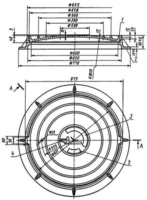
The manhole hatch is heavy ( Luke T (S250) K.1-60 ) - this is a manhole body and a cover installed on the opening of manholes for sewerage, water supply and other engineering networks. Heavy hatches are most often used in road and industrial construction. Hatch T (C250) K.1.60 is cast from the most durable cast iron of grade no lower than 110. A heavy hatch is used to protect well shafts on highways with heavy traffic and in industrial zones. The norms and standards for the production of hatches are enshrined in GOST 3634-99.
due to its weight (110) it is impossible to lift and mount without the use of special devices. The need for such a weight is explained by the fact that when using them on roads with heavy traffic, cast-iron sewer manholes must be in a static position, and even a slight shift in the structure threatens the movement of vehicles. The solid mass of the cast-iron hatch guarantees greater stability during operation.
Hatch T (S250) K.1-60 is produced with a diameter of 830 mm. The heavy manhole cover type T must withstand a significant load kN.
Hatch T (C250) K.1.60 has a round shape, the body is flat and the cover is flat or convex (so that precipitation does not collect on the surface),
Traditionally, cast-iron manhole covers are made ribbed - thereby achieving greater hatch strength and better grip when driving. The upper surface of the hatch cover T has a relief from 3 to 8 mm high, often the relief takes the form of various patterns. The ribs on the outer surface of the heavy hatch cover T can have both a wavy and a tangential shape.
The cast-iron manhole cover can be attached to the body using one or 2 hinges with a lock, which provides additional protection against unauthorized entry into the well by outsiders. The internal locking devices of the hatch are made of steel grade not lower than St3 with anti-corrosion coating.
Also, the cover of the heavy manhole has a hole for sampling gas contamination (except for plumbing). must have an elastic seal between the lid and the body.
Product marking
On the surface of the hatch cover, parallel to the center line, bounded by an annular rib, the symbol of the hatch, the year of its manufacture and the manufacturer's trademark are cast.
The marking of a heavy type hatch depends on the version, where the design differences of the products are indicated by numbers. The number 1 denotes hatches for general purposes, 2 - the presence of a locking locking device, 3 - the presence of a recess in the structure of the cover for filling with concrete, 4 - the presence of a device for lifting the cover using a standard lifting mechanism, 5 - hatches with reinforced body sealing, 6 - hatches with a two-piece lid, 7 - with a lid hinged to the body, 8 - square or rectangular hatches.
Also on the manhole cover indicate the designation of the engineering network, the well of which the hatch will cover. Name of engineering networks for which the hatch is intended:
- B - plumbing;
- G - fire hydrant;
- K - household and industrial sewerage;
- D - rain sewer.
- TS - heating networks
- GS - gas network
- GTS - urban telephone network.
The symbol of the hatch should consist of the type of hatch, version or several versions, overall dimensions of the hatch in centimeters and the designation of this standard. You can also find marking with other letter designations. This is nothing more than the compliance of domestically produced hatches with European standards. So hatch T corresponds to the class C250; hatch C - class B125, etc.
As an example of a heavy hatch symbol, consider:
- T - hatch type (heavy);
- C250 - compliance with the European standard;
- Letters - the name of the engineering network;
- The first digit is the hatch execution index;
- The second digit is the diameter of the manhole 650mm;
- GOST 3634-99 - an indication of the state standard.
Product quality control
Casting Luke T (C250) K.1.60 should not have significant defects and cracks that could affect the strength of the product. Shells with a diameter of more than 10 mm and a depth of more than 3 mm are not allowed. The lid should fit snugly against the supporting surface of the housing - the gap between the lid and the housing is not more than 3 mm. The deviation of the straightness of the supporting surface should not exceed 2 mm.
On acceptance tests hatches C, the appearance of all covers and hatch bodies, as well as the mechanical strength of the covers (at least 2 hatches from a batch) are controlled.
Technical certificate, which must necessarily accompany a batch of cast-iron hatches, must indicate:
- name or trademark of the manufacturer;
- product marking;
- lot number;
- the number of hatches in the party;
- warranty period of operation;
- stamp and date of acceptance by technical control;
- designation of the state standard.
Transportation and storage.
Heavy hatches are transported by various vehicles packed in bags tied with wire. Luke T (S250) K.1-60 is covered by the manufacturer's warranty. The warranty period is 3 years from the date of putting the hatches into operation, but not more than 5 years from the date of shipment of products to the customer.
At the request of the customer, the name of engineering networks (marking on the cover) can be entered into the symbol of the hatch:
- IN- water pipes;
- D- rain sewerage;
- G, PG- fire hydrant, underground fire hydrant;
- T/C- heating system;
- TO- domestic and industrial sewerage;
- HS- gas network;
- GTS- city telephone network;
- MG- main gas pipeline;
- T- telephone (telephone network);
And also we offer cable consoles cast iron ( KKCH) designed for layout and fastening of cables in cable communication wells, shafts, collectors for telecommunications.
Cast iron support consoles are available in the following modifications according to GOST 8850-80,
KKCh-1,KKCh-2,KKCh-3,KKCh-4(single, double, triple and quadruple).
LIGHT CAST IRON HATCHES. Type L GOST 3634-99;
They are used on manholes of engineering urban communications of thermal, cable and gas networks, water supply networks, sewerage systems, in green spaces and pedestrian zones.
Light hatch "L" (А15):

Rated load on the hatch cover - 1.5 tons (15 kN);
opening size - 600mm;
Weight - 58 kg.
Light hatch "L" (А30):

Rated load on the hatch cover - 3 tons (30 kN);
The light hatch has overall dimensions - 740x60mm;
opening size - 600mm;
Weight - 62 kg.
HATCH CAST IRON MEDIUM. Type C GOST 3634-99;
They are used for installation on manholes of water supply, sewerage, heat and gas supply networks, in pedestrian areas, on roadsides and car parks, where the load will be moderate on the manhole cover (nominal load no more than 12.5 tons).
Medium hatch "C" (B-125):

Rated load on the hatch cover - 12.5 tons (125 kN);
The light hatch has overall dimensions - 760x90mm;
opening size - 600mm;
Weight - 65 kg.
HEAVY CAST IRON HATCH Type T GOST 3634-99;
They are used for installation on manholes of water supply, sewerage, heat and gas networks located on urban roads with heavy traffic, where the load on the hatch will be large (nominal load of the heavy cast-iron hatch "T" (S-250) is not more than 25 tons).

Hatch heavy "T" (S-250) 1-60 four-eye:
Weight - 106 kg.
Heavy hatch "T" (S-250) (K, V, D, T / S, G):
Rated load on the hatch cover - 25 tons (250 kN);
The light hatch has overall dimensions - 870x120mm;
opening size / cover diameter - 600/636mm;
Weight - 106 kg.
Heavy hatch "T" (S-250) with a locking device:
Rated load on the hatch cover - 25 tons (250 kN);
opening size / cover diameter - 600/775mm;
Weight - 106 kg.
*Additional manhole covers with locking device ( DKL), is placed under an external cast-iron cover and does not require changes in existing designs of manholes and wells, locking devices prevent unauthorized access to the well.
 Suitable for all types of hatches (light, heavy, heavy main).
Advantages of using the Cast Iron Hatch Locking Device (DKL):.
1. Mobility, light weight and ease of installation in a mounted hatch;
2. When the lid breaks or is stolen, the cast iron manhole lock (DCL) will prevent debris from entering the well;
3.Reliable, tested design.
CAST IRON HATCH MAIN Type TMP GOST 3634-99;
They are used on main roads (city and intercity roads with the movement of heavy freight and public transport) and other objects where the load on the hatch will be large (the nominal load of the heavy cast-iron hatch TM D400 is not more than 40 tons).
Trunk hatch "TMR" (S-250) (K,V,D,T/S,):

Rated load on the hatch cover - 25 tons (250 kN);
The light hatch has overall dimensions - 870x120mm;
opening size / cover diameter - 600/636mm;
Weight - 125 kg.
CAST IRON TELEPHONE HATCHES. GTS type GOST 8591-76;
Hatch type L(lightweight) is designed for installation on cable manholes and telephone duct boxes on sidewalks and footpaths.
Telephone sewer hatch "L":

Rated load on the hatch cover - 6.8 tons (68 kN);
The light hatch has overall dimensions - 780x75mm;
opening size / cover diameter - 600/667mm;
Weight - 87 kg.
Hatch type T(heavy) is intended for installation on cable manholes and telephone duct boxes on public roads.
Telephone sewer hatch "T":

Rated load on the hatch cover - 17 tons (170 kN);
The light hatch has overall dimensions - 850x110mm;
opening size / cover diameter - 600/686mm;


")


