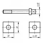
Eccentric clamps are easy to manufacture and for this reason they are widely used in machine tools. The use of eccentric clamps can significantly reduce the time for clamping a workpiece, but the clamping force is inferior to threaded clamps.
Eccentric clamps are made in combination with and without clamps.
Consider an eccentric clamp with a clamp.
Eccentric clamps cannot work with significant tolerance deviations (±δ) of the workpiece. For large tolerance deviations, the clamp requires constant adjustment with screw 1.
| Eccentric calculation |
 The materials used for the manufacture of the eccentric are U7A, U8A With
heat treatment to HR from 50....55 units, steel 20X with carburization to a depth of 0.8... 1.2 With hardening HR from 55...60 units.
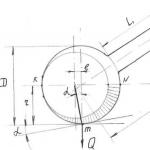
Let's look at the eccentric diagram. The KN line divides the eccentric into two? symmetrical halves consisting, as it were, of 2 x wedges screwed onto the “initial circle”.
The eccentric rotation axis is shifted relative to its geometric axis by the amount of eccentricity “e”.
Section Nm of the lower wedge is usually used for clamping.
Considering the mechanism as a combined one consisting of a lever L and a wedge with friction on two surfaces on the axis and point “m” (clamping point), we obtain a force relationship for calculating the clamping force.

where Q is the clamping force
P - force on the handle
L - handle shoulder
r - distance from the eccentric rotation axis to the point of contact With
workpiece
α - angle of rise of the curve
α 1 - friction angle between the eccentric and the workpiece
α 2 - friction angle on the eccentric axis
To avoid the eccentric moving away during operation, it is necessary to observe the condition of self-braking of the eccentric

 where α -
sliding friction angle at the point of contact with the workpiece ø -
friction coefficient
For approximate calculations of Q - 12P, consider the diagram of a double-sided clamp with an eccentric
 |
Wedge clamps
Wedge clamping devices are widely used in machine tools. Their main element is one, two and three bevel wedges. The use of such elements is due to the simplicity and compactness of the designs, speed of action and reliability in operation, the possibility of using them as a clamping element acting directly on the workpiece being fixed, and as an intermediate link, for example, an amplifier link in other clamping devices. Typically self-braking wedges are used. The condition for self-braking of a single-bevel wedge is expressed by the dependence
α > 2ρ
Where α - wedge angle
ρ - the angle of friction on the surfaces G and H of contact between the wedge and the mating parts.

Self-braking is ensured at angle α = 12°, however, to prevent vibrations and load fluctuations during the use of the clamp from weakening the workpiece, wedges with an angle α are often used<12°.
Due to the fact that decreasing the angle leads to increased
self-braking properties of the wedge, it is necessary when designing the drive to the wedge mechanism to provide devices that facilitate the removal of the wedge from the working state, since releasing a loaded wedge is more difficult than bringing it into the working state.

This can be achieved by connecting the actuator rod to a wedge. When rod 1 moves to the left, it passes path “1” to idle, and then, hitting pin 2, pressed into wedge 3, pushes the latter out. When the rod moves back, it also pushes the wedge into the working position by hitting the pin. This should be taken into account in cases where the wedge mechanism is driven by a pneumatic or hydraulic drive. Then, to ensure reliable operation of the mechanism, different pressures of liquid or compressed air should be created on different sides of the drive piston. This difference when using pneumatic actuators can be achieved by using a pressure reducing valve in one of the tubes supplying air or liquid to the cylinder. In cases where self-braking is not required, it is advisable to use rollers on the contact surfaces of the wedge with the mating parts of the device, thereby facilitating the insertion of the wedge into its original position. In these cases, it is necessary to lock the wedge.
Eccentric clamps are fast-acting, but they develop less clamping force than screw clamps and have limited linear movement.
In machine tools, round and curved eccentric clamps are used. The round eccentric used in the proposed design is a disk rotated around the O axis, displaced relative to the geometric axis of the eccentric by a certain amount e, called eccentricity. To secure the workpiece, eccentric clamps must be self-locking.
Round eccentrics are made of 20X steel, cemented to a depth of 0.6....1.2 mm and then hardened to a hardness of 58....62HRC e. Some types of round eccentrics are made according to GOST 9061-68
It is known from theoretical mechanics that the conditions for self-braking of two rubbing bodies are as follows: the friction angle is greater than or equal to the angle of elevation at which friction occurs. Consequently, if the angle of lift of the eccentric in a certain position is not greater than the angle of friction, then the eccentric is self-braking. Self-braking eccentrics do not change their position after clamping the workpiece. Self-braking of eccentric clamps is ensured at a certain ratio of its outer diameter and eccentricity e.
When calculating the main dimensions of a round eccentric, it is necessary to have the following values.

Round eccentric eccentricity (44):

The radius of the outer surface of the eccentric is determined from the condition of its self-braking:
The angle of rotation of the eccentric corresponding to the clamp position that is least favorable for self-braking.
Eccentric clamps, as opposed to screw clamps, are quick-acting. It is enough to rotate the handle of such a clamp less than 180° to secure the workpiece.
The operation diagram of the eccentric clamp is shown in Figure 7. When the handle is turned, the radius of rotation of the eccentric increases, the gap between it and the part (or lever) decreases to zero; The workpiece is clamped by further “compacting” the system: eccentric - part - fixture.
Figure 7 - Scheme of eccentric clamp operation
To determine the main dimensions of the eccentric, you should know the magnitude of the workpiece clamping force Q, the optimal angle of rotation of the handle for clamping the workpiece ρ, and the tolerance for the thickness of the workpiece being fixed δ.
If the angle of rotation of the lever is unlimited (360°), then the magnitude of the cam eccentricity can be determined by the equation
where S 1 is the installation gap under the eccentric, mm;
S 2 - eccentric power reserve, taking into account its wear, mm;
Tolerance for workpiece thickness, mm;
Q – workpiece clamping force, N ;
L - clamping device rigidity, N /mm(characterizes the amount of spin of the system under the influence of clamping forces).
If the angle of rotation of the lever is limited (less than 180°), then the amount of eccentricity can be determined by the equation
The radius of the outer surface of the eccentric is determined from the condition of self-braking: the angle of rise of the eccentric, made up by the clamped surface and the normal to the radius of its rotation, must always be less than the friction angle, i.e.
(f=0.15 for steel),
Where D And R- the diameter and radius of the eccentric, respectively.
The clamping force of the workpiece can be determined by the formula
![]()
Where R - force on the eccentric handle, N (usually accepted ~ 150 N );
l - handle length, mm;
– friction angles between the eccentric and the part, between the trunnion and the eccentric support;
R 0 - eccentric rotation radius, mm.
To approximate the clamping force, you can use the empirical formula Q12 R(at t=(4- 5) R and P=150 N) .

a, b - for pressed flat workpieces; b- for fastening flat workpieces using a swinging beam; G- for tightening the shells using a flexible clamp
Figure 8 - Examples of eccentric clamps of various designs
TaskNo. 3 “Calculation of eccentric clamp parameters”
Using the tutor’s input data, select and calculate the parameters of the eccentric clamp (Figure 7), if the product must be pressed with force Q, clamping device rigidity L, the angle of rotation of the lever is unlimited, the installation gap under the eccentric S 1, the power reserve of the eccentric, taking into account its wear S 2, tolerance for the thickness of the workpiece, the welder is right-handed .
Calculate the diameter of the eccentric.
Determine the length of the eccentric handle l.
Draw a sketch of the clamp. Select the material from which the clamp should be made.
Table 4 - Problem options
|
Q, kN |
L, N/mm |
S 1 , mm |
S 2 , mm |
The working part of these clamps is made in the form of cylindrical or curved cam rollers. Clamping with their help is faster than with screw devices, however, the possibility of their use is more limited compared to screw devices, because they work well only with minor deviations in the dimensions of the surfaces on which the workpieces are strengthened and in the absence of vibrations.
1 – cylindrical eccentric is widely used because easy to make. The disadvantage of this design is the small stroke and inconsistent braking properties.
2 – characterized by the presence of a cut to increase the stroke when installing and removing the workpiece.
3 – has the greatest application in practice. The working surface of the eccentric is limited to a sector of 60 - 90°, the rest is cut off. It is advisable to use such a cam to retract the clamping mechanism when installing and removing parts over significant distances (up to 45 mm).
4 – the clamp is a double cam 3 and is used in centering mechanisms and floating vices.
All these cams are fixed on the shaft and, using a handle attached to the shaft, rotate with it.
5 – eccentric lever, because the eccentric cam in it is connected to the handle. Their range of action is less than that of cams.
Workpiece clamping force:
![]()
where Q is the force on the handle;
L – handle length;
j is the angle of static friction (» 8°);
e – eccentricity;
a - wedge lift angle;
6 and 7 – eccentric rollers. They are used as locking mechanisms for precisely executed moving parts of devices. In these cases, significant eccentricity is not required, and therefore a small diameter roller can be used. preference should be given to double-support rollers 6, as they are more rigid and reliable against bending.
The working surface of the eccentrics can be made in the form of a circle and curved - in the form of an involute and an Archimedes spiral. Their difference is that in the development of circular eccentrics the wedge turns out to be curved with a limiting angle a, hence the instability of the clamp. At the same time, the technology for manufacturing circular eccentrics is much simpler than curved ones. The self-braking properties of the eccentrics increase with increasing angle of rotation. Recommended rotation angle a e = 30 - 135°
The material for the eccentrics is 20X steel, carburized to a depth of 0.8 - 1.2 mm and hardened to HRC 55...60.
Eccentric clamps are easy to manufacture and for this reason they are widely used in machine tools. The use of eccentric clamps can significantly reduce the time for clamping a workpiece, but the clamping force is inferior to threaded clamps.
Eccentric clamps are made in combination with and without clamps.
Consider an eccentric clamp with a clamp.
Eccentric clamps cannot work with significant tolerance deviations (±δ) of the workpiece. For large tolerance deviations, the clamp requires constant adjustment with screw 1.
Eccentric calculation
M  The materials used for the manufacture of the eccentric are U7A, U8A With
heat treatment to HR from 50....55 units, steel 20X with carburization to a depth of 0.8... 1.2 With hardening HR from 55...60 units.
Let's look at the eccentric diagram. The KN line divides the eccentric into two? symmetrical halves consisting, as it were, of 2 X wedges screwed onto the “initial circle”.
The eccentric rotation axis is shifted relative to its geometric axis by the amount of eccentricity “e”.
Section Nm of the lower wedge is usually used for clamping.
Considering the mechanism as a combined one consisting of a lever L and a wedge with friction on two surfaces on the axis and point “m” (clamping point), we obtain a force relationship for calculating the clamping force.

where Q is the clamping force
P - force on the handle
L - handle shoulder
r - distance from the eccentric rotation axis to the point of contact With
workpiece
α - angle of rise of the curve
α 1 - friction angle between the eccentric and the workpiece
α 2 - friction angle on the eccentric axis
To avoid the eccentric moving away during operation, it is necessary to observe the condition of self-braking of the eccentric

Condition for self-braking of the eccentric. = 12Р
about chyazhima with expentoik
G  deα
-
sliding friction angle at the point of contact with the workpiece ø
-
friction coefficient
For approximate calculations of Q - 12P, consider the diagram of a double-sided clamp with an eccentric

Wedge clamps
Wedge clamping devices are widely used in machine tools. Their main element is one, two and three bevel wedges. The use of such elements is due to the simplicity and compactness of the designs, speed of action and reliability in operation, the possibility of using them as a clamping element acting directly on the workpiece being fixed, and as an intermediate link, for example, an amplifier link in other clamping devices. Typically self-braking wedges are used. The condition for self-braking of a single-bevel wedge is expressed by the dependence
α > 2 ρ
Where α - wedge angle
ρ - the angle of friction on the surfaces G and H of contact between the wedge and the mating parts.

Self-braking is ensured at angle α = 12°, however, to prevent vibrations and load fluctuations during the use of the clamp from weakening the workpiece, wedges with an angle α are often used<12°.
Due to the fact that decreasing the angle leads to increased
self-braking properties of the wedge, it is necessary when designing the drive to the wedge mechanism to provide devices that facilitate the removal of the wedge from the working state, since releasing a loaded wedge is more difficult than bringing it into the working state.

This can be achieved by connecting the actuator rod to a wedge. When rod 1 moves to the left, it passes path “1” to idle, and then, hitting pin 2, pressed into wedge 3, pushes the latter out. When the rod moves back, it also pushes the wedge into the working position by hitting the pin. This should be taken into account in cases where the wedge mechanism is driven by a pneumatic or hydraulic drive. Then, to ensure reliable operation of the mechanism, different pressures of liquid or compressed air should be created on different sides of the drive piston. This difference when using pneumatic actuators can be achieved by using a pressure reducing valve in one of the tubes supplying air or liquid to the cylinder. In cases where self-braking is not required, it is advisable to use rollers on the contact surfaces of the wedge with the mating parts of the device, thereby facilitating the insertion of the wedge into its original position. In these cases, it is necessary to lock the wedge.

Let us consider the diagram of the action of forces in a single-skew, most often used in devices, wedge mechanism

Let's construct a force polygon.

When transmitting forces at right angles, we have the following relationship

Self-braking occurs at α<α 1 +α 2 Если α 1 =α 2 =α 3 =α the dependence is simpler P = Qtg(α+2φ)
Collet clamps
The collet clamping mechanism has been known for a long time. Securing workpieces using collets turned out to be very convenient when creating automated machines because to secure the workpiece, only one translational movement of the clamped collet is required.
When operating collet mechanisms, the following requirements must be met.
The clamping forces must be ensured in accordance with the emerging cutting forces and prevent movement of the workpiece or tool during the cutting process.
The clamping process in the general processing cycle is an auxiliary movement, so the response time of the collet clamp should be minimal.
The dimensions of the clamping mechanism links must be determined from the conditions of their normal operation when securing workpieces of both the largest and smallest sizes.
The positioning error of the workpieces or tools being fixed should be minimal.
The design of the clamping mechanism should provide the least elastic pressure during the processing of workpieces and have high vibration resistance.
The collet parts and especially the collet must have high wear resistance.
The design of the clamping device must allow its quick change and convenient adjustment.
The design of the mechanism must provide protection for the collets from chips.
Collet clamping mechanisms operate in a wide range of sizes. The practically minimum acceptable size for fastening is 0.5 mm. On multi-spindle bar machines, the diameters of the bars, and
therefore, the collet holes reach 100 mm. Collets with a large hole diameter are used to secure thin-walled pipes, because... relatively uniform fastening over the entire surface does not cause large deformations of the pipes.
The collet clamping mechanism allows for securing workpieces of various cross-sectional shapes.
The durability of collet clamping mechanisms varies widely and depends on the design and correctness of technological processes in the manufacture of mechanism parts. As a rule, clamping collets fail before others. In this case, the number of fastenings with collets ranges from one (breakage of the collet) to half a million or more (wear of the jaws). The performance of a collet is considered satisfactory if it is capable of securing at least 100,000 workpieces.
Classification of collets
All collets can be divided into three types:
1. Collets of the first type have a “straight” cone, the top of which faces away from the machine spindle.

To secure it, it is necessary to create a force that pulls the collet into the nut screwed onto the spindle. The positive qualities of this type of collet are that they are structurally quite simple and work well in compression (hardened steel has a higher permissible stress in compression than in tension. Despite this, collets of the first type are currently of limited use due to disadvantages. What are these disadvantages:
a) the axial force acting on the collet tends to unlock it,
b) when feeding the bar, premature locking of the collet is possible,
c) when secured with such a collet, there is a harmful effect on
d) there is unsatisfactory centering of the collet in the spindle, since the head is centered in the nut, the position of which on the spindle is not stable due to the presence of threads.
Collets of the second type have a “reverse” cone, the top of which faces the spindle. To secure it, it is necessary to create a force that pulls the collet into the conical hole of the machine spindle.

Collets of this type ensure good centering of the workpieces being clamped, since the cone for the collet is located directly in the spindle and cannot
jamming occurs, the axial working forces do not open the collet, but lock it, increasing the fastening force.
At the same time, a number of significant disadvantages reduce the performance of collets of this type. Due to the numerous contacts with the collet, the conical hole of the spindle wears out relatively quickly, the threads on the collets often fail, not ensuring a stable position of the rod along the axis when fastened - it moves away from the stop. Nevertheless, collets of the second type are widely used in machine tools.
Collets of the third type They also have a reverse cone, but they work due to the axial movement of a sleeve with a conical hole, while the collet itself remains stationary.

This design avoids most of the disadvantages inherent in collets of the first and second types. However, one of the existing disadvantages of collets of this type is the increase in overall dimensions of the entire clamping unit in diameter.
For the manufacture of medium and large collets, steel grades 65G, 12KhNZA, U7A, U8A are mainly used. It is considered advisable to use low-carbon case-hardening steels. Experimental data show that case-hardened steels perform no worse than carbon steels. The presence, for example, of nickel in case-hardened steel 12ХНЗА ensures the resistance of the collet to abrasion, and case-hardening gives it relatively good plastic properties. Nevertheless, most factories prefer 65G steel.
R  Let's look at what forces arise when the collet operates in the absence of an axial stop.
P = (Q+Q")tg( α + φ )


Q - clamping force over preparations VCI is calculated using the formula
M - cutting moment M = P z V let’s substitute the values of the cutting moment
Where - V is the distance from the axis to the point of application of the cutting force R is the radius of the workpiece into the clamping areas.q is the component of the force that shifts the workpiece along the axis.
ƒ - deflection arrow. k - safety factor
Q 1 - the force required to compress all the collets until they come into contact with the workpiece.
φ - friction angle between the collet and the body

where E is the elastic modulus.
1 - moment of inertia of the sector in the collet.
f - deflection arrow.
l is the length of the collet blade from the contact point to the middle of the cone.
Vacuum clamping devices
Vacuum clamping devices operate on the principle of direct transmission of atmospheric pressure to the workpiece being clamped.
Vacuum devices can be used to hold workpieces made of various materials with a flat or curved surface. The clamping force is sufficient for finishing and finishing operations. Vacuum devices are very effective for securing thin plates. The base surfaces of the workpiece can be either cleanly processed or black, but fairly smooth without any visible depressions or protrusions.
If there are polished surfaces, installation of workpieces without compaction is allowed. The workpieces are detached by connecting the cavity from which the air with the atmosphere is pumped out.

The force pressing the workpiece is calculated using the following formula
Q = F(l,033-P) kg.
where F is the area in cm 2, the boundaries of which are taken along the seal line P is the vacuum created in the cavity of the device by the suction device.
In practice, a vacuum of 0.1 0.15 kg/cm 2 is used
Using a deeper vacuum is expensive and the clamping force increases only slightly.
For uniform multi-point clamping of the workpiece to the plate, a large number of evenly spaced holes are made on the mounting plane.

In this case, the fastening takes place without local buckling and warping of the workpiece. The vacuum for individual installations is created:
a) centrifugal pumps P = 0.3 kg/cm 2
b) single-stage piston P = 0.005 kg/cm 2
two-stage R= 0.01 kg/cm 2
