Car alarm is an effective security system. It is often used on modern cars. Perhaps the alarm will not save you from theft, but it will help stop attempts at damage. It often happens that in the yards, children, by chance or not by chance, can hook the car. Also, shelling of cars from pneumatic weapons is not uncommon. With the help of the security complex, the owner will be able to respond in time to the damage. Alarms can scare away criminals - there are many such cases. It is best to entrust the connection of the alarm to experienced professionals, but if there are none, you can try to do it yourself. The operation is not that difficult. Let's see how to connect the alarm.
Standards and schemes from different manufacturers
If we analyze the connection schemes for car alarms from various manufacturers, we can conclude that there are no standard schemes and a single unification. Wires of the same color from different manufacturers solve different problems.
A particular brand has its own method of installing and connecting devices.
Installing the alarm unit
The first step is to install the main unit. The main problem for many is where to connect the alarm? It is installed in the passenger compartment, in a place known only to the driver. If this is a serious security complex, then there are several such blocks - they are best placed in different places. This will help buy time when the car thieves will take over. Before connecting the alarm sensor, you need to disassemble the left rack. It is recommended to install it there.
As a standard, a simple alarm unit is hidden inside the dashboard, but other places can be found. It is desirable to fix the block. It can be glued on double-sided tape or attached with self-tapping screws. Also at this stage, you should deal with the electrical circuit - it shows how to connect the alarm to power, turn signals, central locking solenoids.
Wire pulling
There are usually many cords. It is better to stretch them in closed places, reliably protected from moisture and high temperatures. It is better to stretch the wiring in the braid, and it is recommended to use plastic clamps for fastening on the body. They need to be tightened at a distance of no more than 20 centimeters from each other. Whatever the alarm, it has redundant wires. The door and trunk opening switches are different wires. But since the function is one, they are connected through one cord. The second one should be cut off. Later, when there are any problems with the alarm, it will be easier to determine the possible cause and find the circuit in which there are malfunctions. The practice of installing alarms shows that complete wires are often not enough. Therefore, it is better to purchase additional ones in advance.
Power connection
Everything is simple here. It is enough to find a large thick cable on the fuse box of the car - this is the positive wire. Weight is taken from the body. The wires are stripped and connected using quick-detachable terminal blocks.

Alarm connection points
Consider popular connection points. The main plus for power can be found in the ignition switch. The starter contact with negative polarity is also in this location. The ACC element is located there. The ignition contact with positive polarity can be found in the contact group of the lock.

The regular lock in most cases is connected through a negative wire. But there are exceptions. Doors and their limit switches are controlled by positive polarity, but it is better to double-check everything according to the diagram. The dimensions are connected to the positive wire, and the locations of these wires are marked in the fuse box. In most cases, these points are enough to solve such a problem as connecting an alarm to a VAZ (whether it is a "Classic" or a modern "Vesta").
Connection of external light signals
In almost all devices, the indication is carried out through the direction indicator lamps. It is better to use two wires - each is responsible for its own side. It is advisable to connect through diodes to avoid shorting the sides. It is more rational to connect through the dimensions - they have less power consumption, and you also need one wire without diodes to connect.
Connecting to the central lock
Perhaps the alarm will not save from but will make the life of the driver more comfortable. Many systems have central locking control. Let's see how to connect the locks to the alarm. We will assume that the solenoids have already been installed.
The first step is to understand the colors of the wires and what commands they perform. For this, it is better to use a multimeter. The search algorithm for the desired contact is quite simple: the device is set to the resistance measurement mode. The minus is connected to one of the contacts, a button is pressed that closes the door. With a multimeter, you need to look for zero resistance. After that, the button can be released. When the resistance is infinity, this is the desired contact. They are also looking for a second contact. This is done in a similar way.

Then the threshold is removed from the driver's side. Next, they find the necessary wires that were determined in advance. Alarm wires are connected to them, which are responsible for opening and closing doors.
How to connect the Starline alarm?
The Starline company produces popular modern security systems with an autorun function, as well as "quick dialogue" functions that exclude the possibility of hacking the security complex with a code grabber. Most models have 60 or more standard and programmable functions.

For installation, you will need an alarm, a solenoid on the driver's door, a soldering iron and soldering materials, protective diodes, electrical tape. Before connecting the alarm, remove the plastic of the steering shaft, unscrew the screws for fastening the dashboard, as well as other nuts and screws. Then, an LED is installed in the windshield rack, as well as a shock sensor. A service button is installed anywhere. These security systems have an antenna. It is better to mount it on the windshield. Next, connect the wires from the 18-pin connector according to the instruction diagram. So, the black wire is connected to the mass, the red one - to the "plus". And further according to the scheme.
How to tie a keychain?
In addition to the fact that the driver faces the task of installing an alarm, he must solve another problem - how to connect Sometimes they are not programmed. A key fob or radio transmitter is the main device that allows you to control the security complex. If the alarm is new, then reprogramming is not necessary. If the car is used, then it is better to reprogram.

To begin with, the unit is transferred to the service mode, which allows you to perform maintenance on the device. To switch to this mode, there is a special combination of pressing certain buttons - each manufacturer has its own.

First you need to disarm the alarm. The Valet button is pressed several times, and then the ignition is turned on. If you hear several beeps, you have successfully logged in. Next, you need to press a few buttons indicated in the instructions, after which a beep will sound. The key fob is programmed and the system remembers it. You can freely use the alarm.
Conclusion
Here's how to wire an alarm with your own hands. In general, the process is simple and does not require special skills, but it is not always possible to set everything up correctly on your own. If the car has a lot of electronic systems, it is better to trust professionals. But a simple budget system can be connected independently, in half a day without experience.
Connecting a car alarm to the lock is a time-consuming and difficult process, which is recommended to be carried out in a car service. Having a desire and having read this instruction, it is quite possible to do it yourself. A weighty argument in favor of personally connecting a security device to the central lock is that, violating the installation algorithm adopted by professionals, it becomes much more difficult to break into a car.
Varieties of elements of the central lock
Central locks have a simple structure:
- input sensors. These are lock microswitches and machine door limit switches. The microswitches determine the actual location of the central locking elements. The limit switches determine the location of the doors and send a message to the control unit.
- Executive mechanisms(also called actuators). They are DC electrical machines that are connected to the converter. Pneumatic actuator may be used.
- Control block. Acts as a transmitter of certain messages to the control units, as well as to the actuators of the trunk roof lock and to the gas tank hatch.

The scheme of the central lock in the car
Do-it-yourself car alarm connection
Security mechanisms are quickly installed in car services. Consider how to connect them yourself. This process has several parts. The result directly depends on whether you follow the instructions.
Before directly connecting the alarm to the central lock, you need to familiarize yourself with the structure of the lock itself. After that, we are looking for access points that are shown in the diagrams of instructions for using and installing the device on a vehicle. Alarms like starline a91 are universal, they are suitable for installation on cars with different types of engines (turbocharged, diesel or gasoline) with both automatic and manual transmissions. 
Work materials
To install the alarm you will need:
- insulating tape;
- screwdriver;
- protective LED;
- driver's door activator;
- soldering iron (with rosin and solder);
- the alarm itself.
Important! Do not start the connection without first reading the theoretical material.
Step-by-step instruction
It is worth remembering that the methods of installing the security mechanism may differ from each other (most often it depends on the manufacturer). After all the materials have been collected and all the introductory information has been read, you can begin the installation.
- Shock sensor connection. This stage is easy. The sensor is connected to the block through a switching connector with three pins (which is located on the right side from the bottom of the block body). Connect the LED indicator connector on the left side of the alarm unit housing. Connect the button to the contact located on the bottom of the alarm unit housing.
- Central locking. We connect the yellow wire and the yellow wire with a black stripe to the positive terminal of the battery (“+”). We connect the orange wire and the orange wire with a black stripe to the negative terminal of the battery (“-”). Connect both remaining white wires to the central ignition lock actuator.
- Signaling. Has 10 wires of different colors.
Video: connect the alarm
Consider their connection:
- yellow wire(uppermost) connect to the contacts of the relay power coil. Normally closed contacts of this relay are inserted into the place of the break in the power supply circuit of the ignition coil. You need to cut the cable that connects the relay power coil and the ignition switch. The ends formed after cutting must be connected to two relay contacts (green wires). Then, connect the wiring coming from the ignition switch to another contact of the relay coil;
- black wire you need to connect to the negative terminal of the battery (the orange and orange-black wires from the central lock are also connected to it);
Important! It is necessary to disconnect the battery for the period of connection, so as not to damage the electrical wiring of the vehicle.
- both wires are brown connect to the turn signals (the first to the right side, the second, respectively, to the left);
- connect the pink wire to the siren (to its red wire). The black cable of the siren is connected to the housing or to the negative pole of the battery;
- red wiring connect to the positive terminal. The yellow and yellow-black wires of the central lock must be connected to it;
- green wire(also called "trunk opening minus"). To be able to implement this function, you need to install an additional relay and connect this wire to its supply coil;
- orange wire connect to the brake pedal switch;
- white wire (ACC) must be connected to the ignition lock (to the contact that closes when the key is turned, and the supply voltage appears on it);
- blue wire connect to the door limit switches.

What difficulties may arise and how to overcome them
The connection process is quite time-consuming, so users may experience some problems:
- The problem of choice with a wide variety of security systems. Buyers, choosing an alarm system, first of all, should be guided by their wishes and ideas about the functional features of this device.
- Installation of a car alarm to the central locking system. To solve this problem, it is necessary to determine the points of connection of the security mechanism, taking into account a number of features (a type of alarm, the exclusivity of the car, the location of the central unit of the car alarm of the vehicle).
- The problem of choosing an installation scheme (color designations of various mechanisms may be intended for other functions). It is advisable to use the original diagrams for your car alarm model.
Did you know? The most expensive car in the world is the Italian sports car Lamborghini Veneno Roadster, worth $4.5 million.
Connection diagrams
We present a universal connection scheme.  Wiring diagram Despite the rather time-consuming process of installing a car alarm with your own hands, the efforts spent will not be in vain, because this will save a good amount of money (most often, the cost of professional services is equal to the price of the alarm kit itself).
Did you know?The most stolen cars in the world are brandsMercedes-Benz (C-Class), BMW 3, Infinity (G-series).
In addition, it will bring a lot of pleasure to those who like to do everything with their own hands.
Now it is fashionable to drive a car to the salon so that an alarm is set there. They do it for some $100 and in less than a day. And then the perplexed car owners cannot figure out why there were malfunctions in the operation of the car or "signals", and even more so they cannot say where the blocks and sensors of the system are located. In addition, if a naive economical car owner entrusted the installation to a "garage service", then it is likely that the location of the signaling blocks became well known to intruders - acquaintances of garage masters.
So, who is interested in setting up the alarm on their own, in order to know all the nuances and not get confused somewhere on the track, read on.
First, let's decide on the location of the main block. Decide for yourself, I will only suggest that it should be in the cabin and not available for quick access so that thieves cannot quickly turn it off. However, they can use other methods of neutralizing the signaling, for example, disconnecting the battery. The solution to this problem can be an autonomous siren and an alarm system with two-way communication or GSM notification.
When choosing the location of the main unit, you must also take into account the length of the standard wires of the control LED, antenna unit (for alarms with two-way communication), shock and microwave sensors. All these wires can, of course, be extended.
The next question is the siren. We put it in the engine compartment so that it is not accessible from the outside (check carefully!), its bell does not "swallow" dirt and, of course, so that the sound from it has the opportunity to spread. It would be useful to install an autonomous siren.
Now we will decide with the power supply of the alarm. From a cigarette lighter? In no case! We lead a separate power wire to the battery. To do this, you can use the technological holes under the panel. Getting to them is difficult, but quite possible. But DO NOT use the hole where the headlight leveler hoses go: this hole is easily accessible from the wheel well, which means that a thief can de-energize the alarm, and all your efforts are in vain.
We pull the ignition switch indicator wire to the ignition switch and cut it in there.
For the front limit switch, we lead the wire into the engine compartment along with the alarm power wire. We put a separate limit switch next to the limit switch for the engine compartment lamp (you don’t need to connect it to this limit switch, including because it often works poorly, it sticks, and split seconds are important for signaling when triggered).
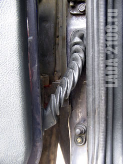
We put the tailgate as shown in the photo. We lead the wire along the left side along the floor. Trunk lighting can be connected to the same limit switch, if you plan one.

The signal LED can be installed on the instrument panel trim. Please note that there the LED is not always visible from ground level and from the first floor. First you need to test its visibility in different places, for example, on a counter, on a panel visor, etc.
We connect the wires of the dimensions not to the dimensions, but to the turn signals - they are more noticeable. The connection is conveniently made near the alarm button (pins 4 and 12), or you can connect to pins 9 and 2 of connector X9 of the mounting block.

It is better to use separate limit switches as door opening sensors, and not connect to regular ones. This is required for models with the APS-4 immobilizer. It is impossible to connect directly to the wires of the limit switches: there will be problems with arming. There are circuits to get around this, but you are tormented to get to the APS wires under the panel behind the skin.
It is also worth noting that the limit switches can be installed not as shown, but on the rear pillar (rear wing for 2108), as is done in foreign cars. Then the limit switches will work earlier when the door is opened.

Next, we put activators that will open / close the door locks. But in the VAZ-2108 there is no wiring in the door. Well, there isn't one! Well, if you come across a used car, and the previous owner did the wiring. I had a used car, but it was from Finland, and people there don't need alarms, believe it or not. I had to do everything from scratch, and this is pretty steamy, because. Initially, the condition was set: do not remove the instrument panel. The photo shows where the holes are drilled. Worth noting - not very successful, because. in the doors, the wires fall into a blind cavity and they have to be led out through the hole. However, this is not scary. In the wing from the inside of the cabin, if you bend the skin, you can find technological holes, through which the wires are brought out. Do not be afraid: carefully open the skin, everything will be found, and then close it without consequences.

The door activators themselves are easy and simple to install. We look at the photo. Something from a "penny" was used as a rubber washer - something that came across in a store. Activators according to this scheme work properly and without problems, incl. in winter.


And finally, do not forget that any alarm is easily bypassed by hijackers. Do not rely on her, she will not protect against theft, and in case of theft from the passenger compartment she will only warn.
Impressions and experience of use
The alarm has been in service for almost 4 years. There were no false positives or failures. The shock sensor has been repeatedly tested in combat conditions. Somewhat annoying is sometimes a small communication distance, to which there is no answer yet. Perhaps interference in the city, but maybe not.Materials and cost
Signaling
about 2000 r.
Activators
Wire NV, PV or MGShV about 15 m (roughly)
limit switches
1 1
sleigh 16.10.2015 22:34how to power the limit switches on my signal + and - there is a one-sided signal on the limit switches 21099 and only on the limit switches in the door - and what to do with the signal +
0 0
Serge 16.10.2015 22:51On many (if not all) signaling there are "+" and "-" exits to the door switches. Read the manual carefully: you need to connect either "+" or "-" depending on the type of car, in the case of all VAZs, "-" is connected. the limit switch closes to ground.
2 2
Deda 23.07.2013 06:59I installed the signaling on my nine, but connected it to the dimensions. I could not figure out how to connect it to the emergency gang. Could you explain to me how it turned out for you?
0 2
SysAdmin 23.07.2013 15:04The article has been updated, it should be clearer now.
4 2
floris-str12v 27.01.2013 20:15to connect the alarm, there is no need to remove the "beard" all connection points are on the mounting block. connector X9 turns blue and blue-black, handbrake brown-blue, door switches white-black or on the driver's stand / depends on the configuration /. On the ignition switch + 12 volt-pink/thick/, ignition-blue-black. starter-red/thick/.
All modern cars are equipped with emergency warning lights, which cannot be said about older cars. For example, this article will focus on the legendary Russian "Kopeyka" - VAZ 2101. Since these cars are not equipped with a light signaling, car owners have to install it on their own. What is the connection scheme for the emergency gang on the VAZ 2101 and how to carry out this task correctly - read on.
[ Hide ]
Purpose and functions of the alarm
An emergency on the VAZ 2101 is used to notify other road users that the vehicle has made an emergency stop due to a malfunction. In accordance with the rules of the road, in the event of a car breakdown, in some cases, the driver is required not only to turn on the emergency gang, but also to put up the appropriate sign. Moreover, it must be set at a certain distance from the car - this issue is regulated by traffic rules.
Installation and configuration instructions
Installing an emergency gang on a VAZ 2101 is not a particularly difficult task, almost everyone can handle it. To properly connect an emergency gang to the VAZ 2101 with your own hands, you need to prepare everything that you may need to complete the task.
A set of tools and materials
So, what you need to prepare before you start the process:
- Locksmith tools, including wrenches, screwdrivers, pliers, etc.
- Insulating tape.
- A four-contact light signaling relay from the Six.
- Six pin activation button.
- Five meters of mounting wire (video by Alex Gordon).
Algorithm for doing work
So, let's start the process:
- First you need to dismantle the center console. To do this, unscrew the bolts that secure the trim to the steering column. You will also need to remove the side windshield pillars.
- Having done this, you can remove the instrument cluster. Be careful not to damage the device.
- Next, disconnect the wires from the light bulb that illuminates the glove box. Then remove the bolts that secure the sides of the glove box to the control panel, as well as the bolts that fix the bottom of it. Having unscrewed all the screws, the glove box itself can be dismantled.
- Now you need to remove the screws that secure the bottom of the dashboard to the front cross member. Then the nuts of the upper fastening are unscrewed, it is best to get to them through the technological openings of the glove box.
- After completing these steps, you can dismantle the handles from the stove control panel. To do this, at the junction of the lever with the handle, use a screwdriver to bend the lower part of the upper handle, and at the bottom handle, you need to bend the top.
- Next, you need to disconnect the connectors with wires from the switches for the backlight of the control panel, side lights, and also the stove. Then, with a wrench, you need to unscrew two more bolts that fix the fasteners of the stove control levers. By following these steps, you will be able to dismantle the control panel.
- Now we proceed directly to the installation and connection of the main elements. First, decide on the mounting location of the system power button. It should be mounted on the center console so that the driver can reach it as quickly as possible if necessary. It is still too early to put the button, but you need to decide on the installation site right now, since it will depend on how much wire you need. Now remove the old turn signal relay from the car and disconnect three cables from it - they are usually colored black, gray-white and orange.
- Next, take a new six-wheel relay. The second contact of the relay must be connected to the wire that was removed from the L contact on the turn signal relay, as well as to the output 7 of the button.
- The first contact of the relay must be connected to the fourth contact on the button itself. The third contact is connected to the cable disconnected from the P contact on the turn signal relay. Then you need to connect the cable from the fourth contact to the mass, that is, the vehicle body - it is best to connect it to the relay fixing nut.
- The next step is to connect the button itself. The fourth contact of the button should be connected to the first contact of the relay being used. Its second contact must be connected to the cable that was disconnected from the positive contact of the rotary relay. The seventh contact is connected to the second contact of the relay, and the first and third contacts are connected to the turn signal stalk switch, in this case the order of connection does not matter.
- Now you just have to connect the eighth pin to any positive cable, as an option, you can wedge into the electrical circuit from the cigarette lighter. In the event that you decide to connect the plus directly to the battery or generator unit, then the circuit will need to be protected with a fuse.
- This completes the installation procedure. You just have to securely fix the wiring to prevent the cables from chafing. Reinstall all previously removed interior trim, center console, glove compartment, etc.

I did it myself almost immediately when I bought the mask (i.e. over a year ago). She got by without it.
Verneus with vaguely incomprehensible wires in the engine bay (as I found out later. With a locking relay that is not connected to anything, and a bunch of wires under the appliance, etc.). In general, some of the previous owners decided to keep it to themselves), as well as non-local door activators, which have been available for a long time.
Read also

Toyota cars deservedly all over the world. They have good reliability and comfort for passengers. The manufacturer produces original engine oil - Toyota 5W30 for its own cars. This product has several varieties, including oil...

New Renault Megane 2016-2017 8212; premiere right around the corner the debut of Renault Megane 2016-2017 will take place on September 15 this year at the Frankfurt Motor Show. The car will be presented personally by CEO Carlos Ghosn. At the same time, Renault...

delivery cabin Filter in the laptop, you need to remove the glove box, for this we unscrew three screws from the topAsk - When should I replace my Nout air conditioner filter? According to the regulations, every 30 t. Ask a question...

Wait, it's been a fast model year, Chevy. General Motors has closed the window to order the 2020 Chevrolet Corvette C8. and, it would seem, early. In an email sent to Chevy dealers and leaked to the Corvette Forum, GM cites high...

To my inquiry about the C-Max gasoline fuel filter, the FMK employee gave the following answer: So the panic has been lifted. Reservoir removal, stock fuel filter removal, TF installation with n Indeed, the Ford C-MAX design does not include an additional...

In most cases, the oil change in the Ford Explorer box is due to a repair of the box itself, or it is replaced with a new one during the operating period to fix the oil leak as it needs to be drained for operation. Automatic oil filling...
They didn't work either)), so the 4-door central locking kit (one 5- and three 2-wire central locking actuators) is a complete set to activate the actuators on board, because they simply dismantled the dead ones and replaced new ones, from found set to another door. Two-wire) (I think no one will have difficulty connecting them, all colors are the only nuance of the rear door. Drive placement. Inside or outside the door, if it is inside, you need to connect the wires opposite here (blue with greenish, greenish) with blue ), so placing it outside, we place the control unit itself without any configuration in any convenient place, I am in the place where the old idle control unit was located (in the oven fan). area), in principle, the control of the central lock can also be refused because signaling It has its own relay to control the drive on board, but I decided to leave it, especially since I myself Control device it connects to it to control the alarm, but later, when the shock sensor and the Valet service button are installed, the siren is in the engine compartment, a couple of cables through the engine compartment partition (green for the hood cover and white and black siren power supply red with red and white stripes ( 12) to a red power cable (12V) located in the center console, a thin antenna wire from the control unit and a black ground wire attached to any I do not stop, I know that I will not have problems stopping in a few points, connecting dimensions (emergency group) to connect the dimensions of two wires (white from the alarm control unit, through which pulse signals can be applied) emergency power button (wires are used red with white stripes and red with black stripes), but since the rotary signals are usually used for this purpose, they can be given to places where there is a baton Turns (wires green with a white stripe, green with a black stripe) they can be found in the connector to the rotary relay or on the back panel of the console, where the fuses are located (connectors JB-07, JB-04), the door ends (in our mask they are negative, tied to body weight (brown wire from control device Alarm signal, it is fed into the connector to the left of the fuse box on a white wire with a red stripe) ACC wire hood end switch at ignition of the connection of the central locking unit to the alarm unit (we have a central circuit with a negative trigger) orange-blue wire with a white stripe from control signal relay block. Connect to ground (housing) the yellow wire from the relay box control device alarm to short white from the central control unit, white from the relay unit to the alarm control to short brown to the central control unit, of course you decide. 🙂
Connect an alarm to turn signals Volga
Hi all! In this video I will show you how connect an alarm clock in turn signals Volga car! As.
Read also

Gas pump on VAZ 2108Electronic gas pumps are installed on VAZ 2108 and VAZ 2109 cars. The purpose of this unit is to supply fuel at a certain pressure to the fuel rail, and from there the injection system distributes fuel to the engine cylinders ...

Fitting a Turbine to a Carburetor Engine The vast majority of motorists seek to maximize the power of their vehicle using the various methods available. Owners of carburetors often ask the question: put the turbine on the carburetor ...

18.16. Airbag (SRS) For maximum effectiveness of the airbag (SRS), the seat and steering wheel must be properly adjusted and the seat belt must be installed. In the event of a collision, the sensor detects the shock load...


